![]()
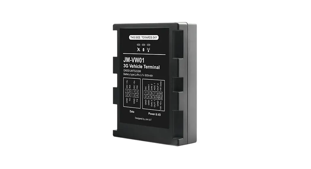
JM-VW01
3G VEHICLE TERMINAL
Quick Start Manual
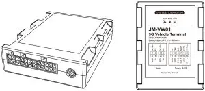
Product overview
| Tracking UMTS & GSM communication GPS & LBS positioning External GPS antenna assisted Real-time location query Track by time/distance/cornering/ignition | Anti-theft Remote power/fuel cut-off SOS emergency call External power supply cut-off alert Geo-fence alert Towing alert | Monitoring Ignition detection Over-speed alert Vibration alert Vehicle door status alert Driver authentication (optional) Fuel level monitoring (optional) Temperature monitoring (optional) Buzzer (optional) |
Specification
| Frequency | GSM: 850/900/1800/1900MHz UMTS: 850/900/1900/2100MHz |
| GNSS Type | All-in-one GNSS receiver |
| Sensitivity | Cold start: <45s Warm start: <35s Hot start: <1s |
| Position Accuracy (CEP50) | 2.5m CEP |
| Dimensions | 85 mm x 65 mm x 20 mm |
| Weight | 92g |
| Backup Battery | Li-Polymer, 500 mAh |
| Operating Voltage | 11V to 36V DC |
| Operating Temperature | —30°C to +70°C |
| —30°C to +70°C for storage | |
| Transmit Protocol | TCP, SMS |
Product setup
Insert SIM and Power on
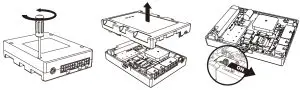
- Loosen the screws, and remove the front cover.
- Insert the SIM card into the card slot with its gold-plated contacts towards the Printed Circuit Board.
- Toggle the battery switch beside the SIM slot to power on.
- Close the cover, and tighten the screws.
Power off
- Disconnect the tracker from external power.
- Remove the cover and switch to “OFF”.
LED indications
Power Status (Red)
Behavior | Meaning |
| Quickly blinking | Low internal battery |
| On for 2s and off for 2s | Charging finished |
| On for 0.1s and off for 2s | Normal mode |
| Solid on | The device is charging |
| Off | Power off or battery error |
GNSS Status (Blue)
| Behavior | Meaning |
| Quickly blinking | GNSS synchronizing |
| Solid on | Positioned |
| Off | GNSS module is in sleep mode or not working |
Wireless Network Status (Green)
| Behavior | Meaning |
| Quickly blinking | Module initializing |
| Slowly blinking | Registered but no inbound acknowledgement |
| Solid on | Network available |
| Off | No signal received or no SIM card detected |
Interface
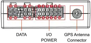
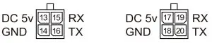
DATA
 I/O AND POWER
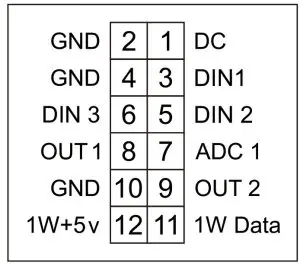
| No. | Meaning | Color | Description |
| 1 | DC IN | Red | Supply voltage 11-36V (max. 40V). Protect device against overvoltage. |
| 2 | GND | Black | Grounding wire |
| 3 | DIN1 | Orange | SOS by default, negative triggered. |
| 4 | GND | Black | Grounding wire |
| 5 | DIN2 | Orange | ACC by default, positive triggered. |
| 6 | DIN3 | Orange | Negative triggered. Configurable. It can connect to the door signal cable to detect its status. (Most Chinese, Korean, and Japanese vehicles are negative edge-triggered.) |
| 7 | ADC | Purple | Input voltage range 0-6V, high precision on 0.01V |
| 8 | DOUT1 | Yellow | Open drain output, immobilization by default. |
| 9 | DOUT2 | Yellow | Open drain output by default. Configurable. Valid: low level (OV) Maximum current for output low voltage (valid):500mA; Maximum voltage for open drain output (invalid):60V You can also configure it as PWM output (output time and pulse width). |
| 10 | GND | Black | Grounding wire |
| 11 | 1-W Data | White | 1-wire communication interface by default. It can be configured as OUT3 (open drain output). |
| 12 | 1-W PWR | Brown | It is the DC 5V output. Drain current 500mA. |
| 13/17 | DC OUT | Red | Output 5V/1A. It supplies power only when device connected to power. |
| 14/18 | GND | Black | Grounding wire |
| 15/19 | RS232-RX | Blue | Input for data receive through RS232 |
| 16/20 | RS232-TX | Green | Output for data transmission through RS232 |
Wiring indication
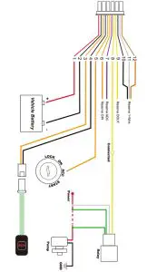
Power connection
The standard power supply ranges from 11V to 36VDC.
During installation, the negative side should connect to the ground. Do not connect with other ground wires simultaneously.
Ignition wire
ACC line (orange) connects to the vehicle’s ACC. detecting ignition. Be sure to check if it’s a real ignition wire i.e.power does not disappear after starting the engine.
Relay wiring
Relay’s white line(85) connects to the positive side of the fuel pump while the yellow line(86) connects to the device’s relay control (yellow line on power cord).
Find the fuel pump of the vehicle and cut off its positive power line. The positive side of the fuel pump connects to the green line (87a) while the side closing to the starter motor connects to the green line(30), as the below chart. The switch of the two green lines has the same effect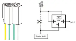
12V relay standard. The device is suitable for vehicles with 12V supply. If the vehicle power supply is 24V, use 24V relay.
SMS configuration
Tracked by mobile phone
Send the command URL# by SMS to the device’s SIM card number. The device will reply with a map link. Click the link to have the location displayed on Google Maps on your mobile phone.
If device in somewhere not positioned, the device will reply “Positioning, please wait for a moment or “Positioning fail”.
Monitored by tracking platform
APN & Server setting
To ensure normal network operation, please confirm your APN and server setting before you login. In most countries, APN could be automatically adapted to local mobile operators. If not, please send SMS to set the APN.
If user name and password are required for APN, please addit into the command.
APN, apnname#
E.g.APN,internet#
APN,apnname,user,pwd#
E.g APN,internet,CLENTE,AMENA#
Confirm the server address and setting with distributors. If the server is incorrect, please send an SMS to change.
SERVER, mode, domain name/ IP, port, 0#
E.g: SERVER, 1, www.ydpat.com. 8011, 0#
SERVER,O,211.154.135.113.8011,0#
mode=1means set with domain name
mode=0 means set with IP address
Please login to the designated service platform and enjoy your monitoring experience.
GPS upload interval setting
By timeinterval (Default Valid) TIMER,T1,T2#
T1 means upload interval when ACC ON
T2 means upload interval when ACC OFF
Range: 5-18000 or 0 (second);0 means no upload
Default valid setting: TIMER,10,10#
Query current TIMER setting: TIMER#
By distance interval (Default OFF)
DISTANCE, D#
D ranges 50-10000 or 0 (meters)
Note: When user enable uploading by DISTANCE, the preset TIME uploading turns invalid.
SOS emergency call
In an emergent case, press SOS for 3seconds to activate SOS alert. The device will send SMS alert to preset SOS numbers and dial the numbers in a loop for three times until the callis picked up.Alarm message will also be sent to the tracking platform.
To add SOS number: SOS,A,number1,number2,number3#
To delete the SOS number: SOS,D,phone number#
Query SOS number: SOS#
Remote power/fuel cut-off
When vehicle is stolen, fuel power command can be sent by platform, APP or SMS.
Notice:
- Make sure ACC is correctly connected.
- When ACC is OFF, the command will be executed immediately.
- When ACC is ON but GPS is not fixed, the command will defer.
- When ACC is ON and GPS is fixed, a command will be executed when vehicle speed is less than 20km/h.
To cut-off/restore the fuelby SMS command, you have to authorize a center number.
Set the center number: CENTER.A.mobile number# Delete the center number: CENTER,D#
Notice:
Only the preset SOS number can seVdelete the center number.
Only one center number can be set.
To cut-off fuel/power connection: RELAY.A#
A=0/1 (O=restore fuel;1=cut-off fuel) Default value:O
E.g.RELAY,1#
Over-speed alert (Default OFF)
SPEED,S,T,V,M#
S=1 means ON; S=O means OFF
T means duration of speeding, ranges 5-600 (second)
SPEED ranges 1-255 (km/h)
M means alert way
M=1 SMS+GPRS;M=O means GPRS
E.g.SPEED,ON,20,100,1#
When vehicle speed is over 100km/h for 10 seconds, you willreceive SMS alert and GPRS alert on server.
Note: SPEED.OFF# Disable over-speed alert
Towing alert (Default OFF)
When vehicle is dragged,device could send alert.
MOVING,S,R,M#
S=1 means ON; S=O means OFF
R means radius, range 100-1000 (meter)
M means alert way
M=1 SMS+GPRS;M=O means GPRS
Note: MOVING,OFF# Disable towing alert
Common SMS setting command
| Command | Description | Remark |
| STATUS# | Check device’s status | |
| VERSION# | Check firmware version | |
| GPRSSET# | Check device network setting | |
| DEFENSE.A# | Delayed defense setting | A:1-60 min, default:10min |
| DEFENSE# | Check the current parameters | |
| SENALM,S,M# | Enabled vibration alarm | S=1 means ON; S=O means OFF M=0/1/2/3, way of alarming, 0: GPRS only, 1:SMS+GPRS, 2: GPRS+SMS+Call, 3: GPRS+Call |
| SENALM,OFF# | Disabled vibration alarm | |
| SENALM# | Check the alarm setting | |
| RESET# | Reboot | Device will reboot in 20s |
| DOOR,X# | Car door negatively/ positively trigger detection setting | X=O,negative triggering; X=1,positive triggering |
Package & Optional accessories
| Standard package |
| JM-VW01 device |
| 12-pin cable |
| Relay(12V/24V) |
| SOS button cable |
| Opt. Iona! accessories | |
| Type | Use |
| 4 PIN connector | For data reading from peripheral accessories |
| External GPS antenna | Achieve reinforced GPS signal |
| Fuel sensor | Detect the fuel level |
| Identify the driver ID and grant permission | |
| RFID | to start the vehicle |
Installation recommendation

- The device should face up to the sky.
- Metal thermal barrier or heating layer of the windshield affects the signa
Troubleshooting
| Type | Use |
| Unable to connect to tracking platform | Check the APN and IP settings. Check whether the data service of SIM card is enabled. Check the balance of SIM card. |
| Tracker shows offline | Check whether external power is still connected. Check if the vehicle entered network blind area. Check the balance of SIM card. |
| Unable to locate | Make sure the top side facing upward without metallic things shielded. Make sure it’s not in area with no satellite coverage. |
| Location drift | In area with poor GNSS signal(tall building around or basement),drifting may happen. Check whether vibration happens around to trigger the accelerator. |
| No command reply | Make sure command fonnat is correct. Vehicle may be in network blind area. Make sure SIM card is well inserted and have SMS service. |
Warranty instructions
- The warranty is valid only when the warranty card is properly completed and upon presentation of the proof of purchase consisting of the original invoice indicating the date of purchase, model and serial No.of the prod we reserve the right to refuse a warranty if this information has been removed or changed after the original purchase of the product from the dealer.
- Our obligations are limited to repair of the defect or replacement the defective part or at its discretion replacement of the product itself.
- Warranty repairs must be carried out by our Authorized Service Centre. Warranty cover will be void, even if a repair has been attempted by any unauthorized service centre.
- Repair or replacement under the terms of this warranty does not provide right to extension or renewal of the warranty period.
- The warranty is not applicable to cases other than defects in material,design and workmanship.
Maintenance Record
| Date | Serviced by |
| Product Model | |
| IMEI Number | |
| Fault Descriptions | |
| Comments |


