steinel ST 052492 RS LED M1 Ceiling Lamp With Motion Sensor Stainless Steel Instruction Manual


steinel ST 052492 RS LED M1 Ceiling Lamp With Motion Sensor Stainless Steel
1. About this document
Please read carefully and keep in a safe place.
– Under copyright. Reproduction either in whole or in part only with our consent.
– Subject to change in the interest of technical progress.
Symbols
 ! Hazard warning!
![]() Reference to other information in the document.
Reference to other information in the document.
2. General safety precautions
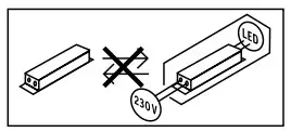
Disconnect the power supply before attempting any work on the unit.
- During installation, the electric power cable being connected must not be live. Therefore, switch off the power first and use a voltage tester to make sure the wiring is off-circuit.
• Installing the sensor-switched light involves work on the mains supply voltage. This work must therefore be carried out professionally in accordance with national wiring regulations and electrical operating conditions. ( e.g.: : VDE 0100, : ÖVE / ÖNORM E8001-1, : SEV 1000 ) - Only use genuine replacement parts.
- Repairs may only be made by specialist workshops.
3. RS LED M1
Proper use
– Sensor-switched indoor light with active motion detector for installing indoors.
The integrated HF sensor emits high-frequency electromagnetic waves ( 5.8 GHz ) and receives their echo. The change in echo caused by the slightest movement within the detection zone of the light is detected by the sensor.
A microprocessor then issues the switch command “switch light ON”. Detection is possible through doors, panes of glass or thin walls.
Note:
The high-frequency power of the HF sensor is approx.
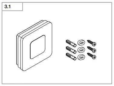
1 mW – that is 1000 times less than the transmission power of a mobile phone or microwave oven. Package contents M1 ( Fig. 3.1 ) Sensor-switched light
3 screws
3 wall plugs
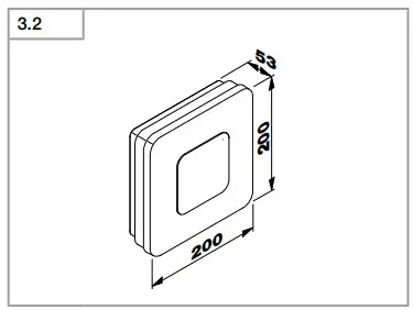
3 spacers Product dimensions M1 ( Fig. 3.2 )
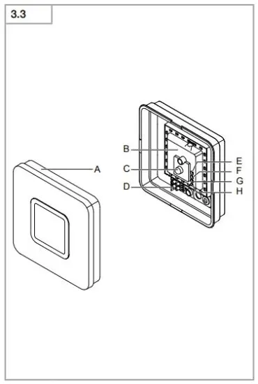
Product components M1 ( Fig. 3.3 )
A Shade
B Electronics enclosure
C HF sensor
D Connecting terminal
E Basic light level
F Time setting
G Reach setting
H Twilight setting
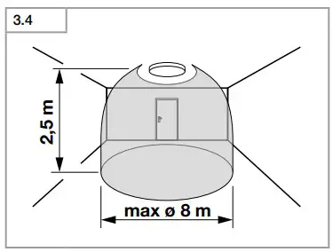
Detection zones for ceiling mounting
M1: Ø 3-8 m ( Fig. 3.4 )
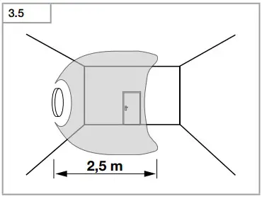
Detection zones for wall mounting M1: 2.5 m ( Fig. 3.5 )
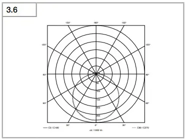
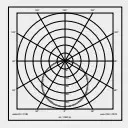
Detection zones may vary slightly depending on type of enclosure used. Luminous intensity distribution ( Fig. 3.6 )
4. Electrical connection
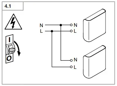
Wiring diagram ( Fig. 4.1 )
The mains power supply lead is a 3-core cable:
= Phase conductor ( usually black, brown or grey )
= Neutral conductor ( usually blue )
= Protective-earth conductor ( green/yellow ) If you are in any doubt, identify the conductors using a voltage tester; then disconnect from the power supply again.
Connect the phase conductor and neutral conductor to the terminal block
Important:
incorrectly wired connections will produce a short circuit later on in the product or your fuse box. In this case, you must identify the individual conductors once again and reconnect them. A mains power switch for turning the unit ON and OFF may of course be installed in the mains supply lead.
The light source of this luminaire cannot be replaced. If the
light source needs to be replaced (e.g. at the end of its service life), the complete luminaire must be replaced.
5. Mounting
- Check all components for damage.
- Do not use the product if it is damaged.
- When installing the sensor-switched light, make sure the installation site is not exposed to vibration.
- Select an appropriate mounting location, taking the reach and motion detection into consideration.
Mounting procedure
- Switch OFF power supply (Fig. 4.1 )
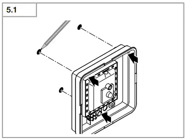
- Mark drill holes (Fig. 5.1)
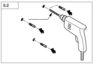
- Drill holes and insert wall plugs (Fig. 5.2 )
- Installation with concealed power supply lead (Fig. 5.3 )
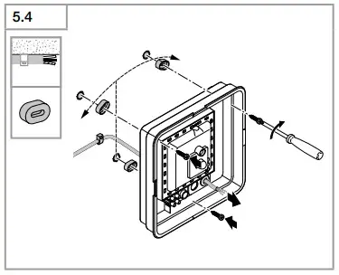
- Installation with surface-mounted power supply lead (Fig. 5.4 )
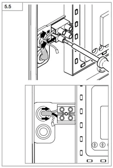
- Connect conductors (Fig. 5.5 )
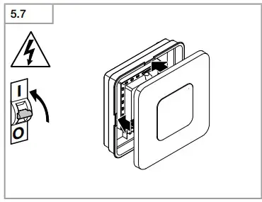
- Switch ON power supply (Fig. 5.7 )
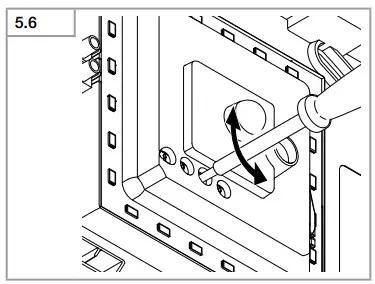
- Make settings (Fig. 5.6 ) – Settings ➔ “6. Function”
- Fit shade (Fig. 5.7 )
6. Function
Factory settings:
Time setting: 5 seconds
Reach setting: M1: max. 8 m
Twilight level: 2000 lux
Basic light level: OFF
The sensor-switched light can be put into service after mounting the enclosure and connecting to the mains power supply. When putting into operation manually at the mains switch, the light will switch OFF after 10 seconds for the calibration phase and is then activated for sensor mode. It is not necessary to operate the mains switch a second time.
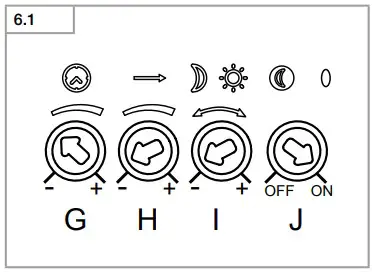
Function – control dials ( Fig. 6.1 )
Time setting ( stay-ON time ) ( Fig. 6.1/F )
The light’s ON time can be set to any period from approx. 5 seconds to a maximum of 15 minutes. Any movement detected before this time elapses will restart the timer.
Note:
After the light switches OFF, it takes approx. 1 second before it is able to start detecting movement again. The light will only switch ON in response to movement once this period has elapsed.
The shortest time setting is recommended when adjusting the detection zone and performing the functional test.
Reach setting ( sensitivity ) ( Fig. 6.1/G )
Reach is the term used to describe the diameter of the more or less circular detection zone produced on the ground for a mounting height of 2.5 m.
– Control dial set to maximum = max. reach
– Control dial set to minimum = min. reach
Twilight setting ( response threshold ) ( Fig. 6.1/F )
The light’s chosen response threshold can be infinitely varied from approximately 2 to 2000 lux.
– Control dial set to = daylight mode ( depending on ambient brightness )
– Control dial set to = twilight mode ( approx. 2 lux )
The control dial must be turned to when adjusting the detection zone and performing the functional test in daylight
Basic light level function ( Fig. 6.1/E )
The basic light level function provides illumination at approx. 10% light output when the brightness setting is reached.
Movement in the detection zone switches the light ON at 100% brightness for the time selected. Light switches OFF completely after the selected time has elapsed. If the brightness setting has not yet been reached,
basic light is switched back ON again.
– Control dial set to = basic light level ON
– Control dial set to 0 = basic light level OFF Basic light is ON when the level of light falls below the brightness threshold. Basic light is always ON when daylight mode is activated. Basic light switches OFF every hour to measure ambient brightness. Basic light switches back ON again after a short period.
Manual override function
If an optional mains switch is installed in the mains supply lead, the following functions are available in addition to simply switching light ON and OFF:
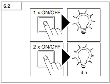
Manual override ( Fig. 6.2)
1 ) Activate manual override: Switch OFF and ON twice. The light is set to manual override for 4 hours. Then it returns automatically to sensor mode.
2 ) Deactivate manual override: Switch OFF and ON once. Light goes out or switches to sensor operation. Important: Switching must take place within 0.2 to 1 second.
7. Disposal
Electrical and electronic equipment, accessories and packaging must be recycled in an environmentally compatible manner.
 Do not dispose of electrical and electronic equipment as domestic waste. EU countries only
Under the current European Directive on Waste Electrical and Electronic Equipment and its implementation in national law, electrical and electronic equipment no longer suitable for use must be collected separately and recycled in an environmentally compatible manner.
Important note: the control gear cannot be replaced.
8. Declaration of Conformity
STEINEL Vertrieb GmbH hereby declares that the
RS LED M1 radio equipment type conforms to Directive 2014/53/EU. The full wording of the EU Declaration of Conformity is available for downloading from the following Internet address: www.steinel.de
9. Manufacturer’s warranty
This Steinel product has been manufactured with utmost care, tested for proper operation and safety and then subjected to random sample inspection. Steinel guarantees that it is in perfect condition and proper working order.
The warranty period is 36 months and starts on the date of sale to the consumer. We will remedy defects caused by material flaws or manufacturing faults. The warranty will be met by repair or replacement of defective parts at our own discretion. The warranty shall not cover damage to wear parts, damage or defects caused by improper treatment or maintenance. Further consequential damage to other objects shall be excluded.
Claims under the warranty will only be accepted if the unit is sent fully assembled and well-packed with a brief description of the fault, a receipt or invoice (date of purchase and dealer’s stamp) to the appropriat
Service Centre.
Repair service:
If defects occur outside the warranty period or are not covered by warranty, ask your nearest service station for the possibility of repair.
10. Technical specifications
| 10. Technische Daten |
| Abmessungen ( H × B × T ) M1: 200 × 200 × 53 mm |
| Netzspannung 220-240 V, 50/60 Hz |
| Leistungsaufnahme (Pon) 8,80 W |
| Lichtstrom * M1: 759 lm |
| Effizienz M1: 86 lm/W |
| Standby Sensor (Psb) 0,39 W |
| Netzstrom 46,50 mA AC |
| Leistungsfaktor 0,93 |
| Farbtemperatur 3.000 K (warmweiß) |
| Farbwiedergabeindex Ra = 83 |
| Mittlere Bemessungslebensdauer L70B50 bei 25°C: >60.000 Std. |
| Farbkonsistenz SDCM Anfangswert: 3 |
 |
| HF-Technik 5,8 GHz ( reagiert temperaturunabhängig auf kleinste Bewegungen ) |
| Erfassungswinkel 360° mit 160° Öffnungswinkel |
| Sendeleistung ca. 1 mW |
| Erfassungsreichweite Ø 3-8 m |
| Zeiteinstellung 5 s – 15 min |
| Dämmerungseinstellung 2-2.000 Lux |
| Grundlicht 10 % |
| Schutzart IP 20 |
| Schutzklasse II |
| Umgebungstemperatur -10 bis +40 °C |
| Energieeffizienzklasse Dieses Produkt enthält eine Lichtquelle der Energieeffizienzklasse „F“. |
11. Troubleshooting
11. Betriebsstörungen |
Störung Ursache Abhilfe |
| Sensorleuchte ohne Spannung ■ Sicherung hat ausgelöst, ■ Sicherung einschalten, tauschen, nicht eingeschaltet, Netzschalter einschalten, Leitung Leitung unterbrochen überprüfen mit Spannungsprüfer ■ Kurzschluss in der Netzzuleitung ■ Anschlüsse überprüfen ■ evtl. vorhandener Netzschalter aus ■ Netzschalter einschalten |
| Sensorleuchte schaltet nicht ein ■ Dämmerungseinstellung falsch gewählt ■ neu einstellen ■ Netzschalter AUS ■ einschalten ■ Sicherung hat ausgelöst ■ Sicherung einschalten, tauschen evtl. Anschluss überprüfen |
| Sensorleuchte schaltet nicht aus ■ dauernde Bewegung im Erfassungs- ■ Bereich kontrollieren bereich |
| Sensorleuchte schaltet ohne ■ Leuchte nicht bewegungssicher ■ Gehäuse fest montieren erkennbare Bewegung ein montiert ■ Bewegung lag vor, wurde jedoch ■ Bereich kontrollieren vom Beobachter nicht erkannt ( Bewegung hinter Wand, Bewegung eines kleinen Objektes in unmittelbarer Leuchtennähe etc. ) |
| Sensorleuchte schaltet trotz ■ schnelle Bewegungen werden zur ■ Bereich kontrollieren Bewegung nicht ein Störungsminimierung unterdrückt oderErfassungsbereich zu klein eingestellt ■ Dämmerungseinstellung falsch gewählt ■ neu einstellen |
Read More About This Manual & Download PDF:
References
 russland.RU Verlag
 Ambergs - apgaismojuma un sensoru tehnikas, santehnikas un celtniecības instrumentu vairumtirgotājs
-
Daljinsko Upravljanje d.o.o.
-
F.Fonseca - High-tech Solutions since 1978
-
Avalehele
-
Hem - En ljusare framtid med ansvarsfull belysning - KHS
-
Narzędzia, elektronarzędzia, oświetlenie, czujniki ruchu
 Minusines - Leader du matériel électrique et de l’éclairage
 Priporočam.si - spletna trgovina za izključno najboljše stvari
-
Roliba - En moderne B2B Handelsvirksomhed med stort udvalg
-
SAOS Teknoloji STEINEL Türkiye Distribütörü | SAOS Teknoloji
-
Steinel купить на steinel-russland.ru
-
【steinel 】施特朗中国官方网站
-
Steinel Group | STEINEL
-
International | STEINEL
-
STEINEL | Steinel Group
-
STEINEL | Steinel Grupul
-
Hem - En ljusare framtid med ansvarsfull belysning - KHS
 Ташев-Галвинг ООД: магазин за машини, инструменти, строителни материали, крепежи и градинска техника
-
Van Spijk | Online B2B inkoopplatform - VanSpijk.nl
-
Energieffektive løsninger - Vilan.no
-
VSA Belgium | De B2B leverancier voor de Belgische markt


