![]() 3.2KVA-3.5KVA-5KVA-5.5KVA
3.2KVA-3.5KVA-5KVA-5.5KVA
INVERTER / CHARGER
User Manual
Purpose
This manual describes the assembly, installation, operation and troubleshooting of this unit. Please read this manual carefully before installations and operations. Keep this manual for future reference.
Scope
This manual provides safety and installation guidelines as well as information on tools and wiring.
SAFETY INSTRUCTIONS
![]() WARNING: This chapter contains important safety and operating instructions. Read and keep this manual for future reference.
WARNING: This chapter contains important safety and operating instructions. Read and keep this manual for future reference.
- Before using the unit, read all instructions and cautionary markings on the unit, the batteries and all appropriate sections of this manual.
- CAUTION –To reduce risk of injury, charge only deep-cycle lead acid type rechargeable batteries. Other types of batteries may burst, causing personal injury and damage.
- Do not disassemble the unit. Take it to a qualified service center when service or repair is required. Incorrect re-assembly may result in a risk of electric shock or fire.
- To reduce risk of electric shock, disconnect all wirings before attempting any maintenance or cleaning. Turning off the unit will not reduce this risk.
- CAUTION – Only qualified personnel can install this device with battery.
- NEVER charge a frozen battery.
- For optimum operation of this inverter/charger, please follow required spec to select appropriate cable size. It’s very important to correctly operate this inverter/charger.
- Be very cautious when working with metal tools on or around batteries. A potential risk exists to drop a tool to spark or short circuit batteries or other electrical parts and could cause an explosion.
- Please strictly follow installation procedure when you want to disconnect AC or DC terminals. Please refer to INSTALLATION section of this manual for the details.
- One piece of 150A fuse is provided as over-current protection for the battery supply.
- GROUNDING INSTRUCTIONS -This inverter/charger should be connected to a permanent grounded wiring system. Be sure to comply with local requirements and regulation to install this inverter.
- NEVER cause AC output and DC input short circuited. Do NOT connect to the mains when DC input short circuits.
- Warning!! Only qualified service persons are able to service this device. If errors still persist after following troubleshooting table, please send this inverter/charger back to local dealer or service center for maintenance.
- WARNING: Because this inverter is non-isolated, only three types of PV modules are acceptable: single crystalline, poly crystalline with class A-rated and CIGS modules. To avoid any malfunction, do not connect any PV modules with possible current leakage to the inverter. For example, grounded PV modules will cause current leakage to the inverter. When using CIGS modules, please be sure NO grounding.
- CAUTION: It’s requested to use PV junction box with surge protection. Otherwise, it will cause damage on inverter when lightning occurs on PV modules.
INTRODUCTION
This is a multi-function inverter/charger, combining functions of inverter, solar charger and battery charger to offer uninterruptible power support with portable size. Its comprehensive LCD display offers user-configurable and easy-accessible button operation such as battery charging current, AC/solar charger priority, and acceptable input voltage based on different applications.
Features
- Pure sine wave inverter
- Configurable input voltage range for home appliances and personal computers via LCD setting
- Configurable battery charging current based on applications via LCD setting
- Configurable AC/Solar Charger priority via LCD setting
- Compatible to mains voltage or generator power
- Auto restart while AC is recovering
- Overload/ Over temperature/ short circuit protection
- Smart battery charger design for optimized battery performance
- Cold start function
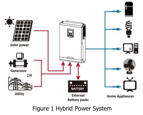
Basic System Architecture
The following illustration shows basic application for this inverter/charger. It also includes following devices to have a complete running system:
- Generator or Utility.
- PV modules
Consult with your system integrator for other possible system architectures depending on your requirements. This inverter can power all kinds of appliances in home or office environment, including motor-type appliances such as tube light, fan, refrigerator and air conditioner.
Product Overview
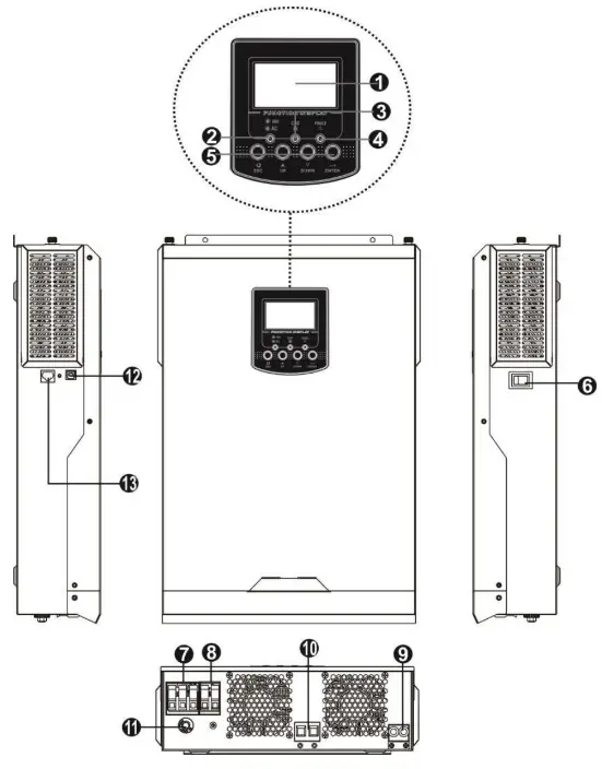
| 1. LCD display | 8. AC output |
| 2. Status indicator | 9. PV input |
| 3. Charging indicator | 10. Battery input |
| 4. Fault indicator | 11. Circuit breaker |
| 5. Function buttons | 12. USB communication port |
| 6. Power on/off switch | 13. RS-232 communication port |
| 7. AC input |
INSTALLATION
Unpacking and Inspection
Before installation, please inspect the unit. Be sure that nothing inside the package is damaged. You should have received the following items inside of package:
- The unit x 1
- User manual x 1
- Communication cable x 1
- Software CD x 1
- DC Fuse x 1
- Ring terminal x 1
- Strain relief plate x 1
- PV wire cover x 1
- Screws x 4
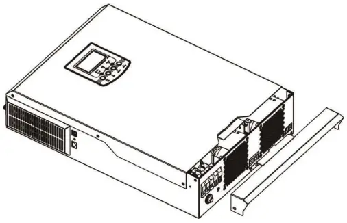
Preparation
Before connecting all wirings, please take off bottom cover by removing two screws as shown below.
Mounting the Unit
Consider the following points before selecting where to install:
- Do not mount the inverter on flammable construction materials.
- Mount on a solid surface
- Install this inverter at eye level in order to allow the LCD display tobe read at all times.
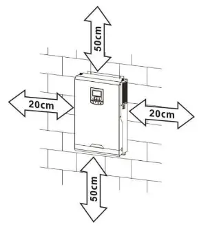
- For proper air circulation to dissipate heat, allow a clearance of approx. 20 cm to the side and approx. 50 cm above and below the unit.
- The ambient temperature should be between 0°C and 55°C toensure optimal operation.
- The recommended installation position is to be adhered to the wall vertically.
- Be sure to keep other objects and surfaces as shown in the diagram to guarantee sufficient heat dissipation and to have enough space for removing wires.

 SUITABLE FOR MOUNTING ON CONCRETE OR OTHER NON-COMBUSTIBLE SURFACE ONLY.
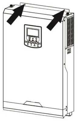
Install the unit by screwing two screws. It’s recommended to use M4 or M5 screws.
Battery Connection
CAUTION: For safety operation and regulation compliance, it’s requested to install a separate DC over-current protector or disconnect device between battery and inverter. It may not be requested to have a disconnect device in some applications, however, it’s still requested to have over-current protection installed. Please refer to typical amperage in below table as required fuse or breaker size.
WARNING! All wiring must be performed by a qualified personnel.
WARNING! It’s very important for system safety and efficient operation to use appropriate cable for battery connection. To reduce risk of injury, please use the proper recommended cable as below.
Recommended battery cable size:
| Model | Wire Size | Cable (mm² ) | Torque value(max) |
| 3.2KVA / 3.5KVA 5KVA / 5.5KVA | 1 x 2AWG | 35 | 2 Nm |
Please follow below steps to implement battery connection:
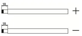
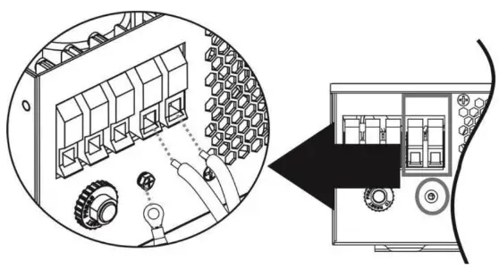
- Remove insulation sleeve 18 mm for positive and negative conductors.
- Suggest to put bootlace ferrules on the end of positive and negative wires with a proper crimping tool.
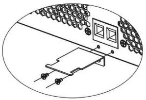
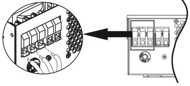
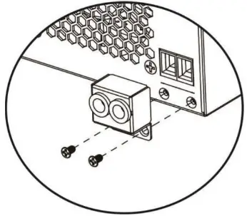
- Fix strain relief plate to the inverter by supplied screws as shown in below chart.


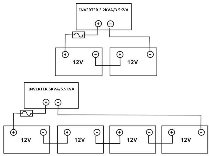
- Connect all battery packs as below chart.
 5. Insert the battery wires flatly into battery connectors of inverter and make sure the bolts are tightened with torque of 2 Nm in clockwise direction. Make sure polarity at both the battery and the inverter/charge is correctly connected and conductors are tightly screwed into the battery terminals.
Recommended tool: #2 Pozi Screwdriver
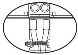
- To firmly secure wire connection, you may fix the wires to strain relief with cable tie.

 5. Insert the battery wires flatly into battery connectors of inverter and make sure the bolts are tightened with torque of 2 Nm in clockwise direction. Make sure polarity at both the battery and the inverter/charge is correctly connected and conductors are tightly screwed into the battery terminals.
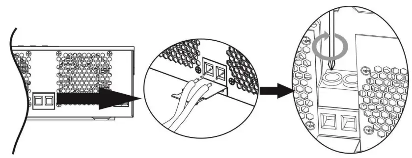
![]() WARNING: Shock Hazard
WARNING: Shock Hazard
Installation must be performed with care due to high battery voltage in series.![]() CAUTION!! Before making the final DC connection or closing DC breaker/disconnector, be sure positive (+) must be connected to positive (+) and negative (-) must be connected to negative (-).
CAUTION!! Before making the final DC connection or closing DC breaker/disconnector, be sure positive (+) must be connected to positive (+) and negative (-) must be connected to negative (-).
AC Input/Output Connection
CAUTION!! Before connecting to AC input power source, please install a separate AC breaker between inverter and AC input power source. This will ensure the inverter can be securely disconnected during maintenance and fully protected from over current of AC input. The recommended spec of AC breaker is 32A for 3.2KVA/3.5KVA and 50A for 5KVA/5.5KVA.
CAUTION!! There are two terminal blocks with “IN” and “OUT” markings. Please do NOT mis-connect input and output connectors.
WARNING! All wiring must be performed by a qualified personnel.
WARNING! It’s very important for system safety and efficient operation to use appropriate cable for AC input connection. To reduce risk of injury, please use the proper recommended cable size as below.
Suggested cable requirement for AC wires
| Model | Gauge | Cable (mm2) | Torque Value |
| 3.2KVA / 3.5KVA | 12 AWG | 4 | 1.2 Nm |
| SKVA / 5.51NA | 10 AWG | 6 | 1.2 Nm |
Please follow below steps to implement AC input/output connection:
- Before making AC input/output connection, be sure to open DC protector or disconnector first.
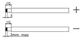
- Remove insulation sleeve 10mm for six conductors. And shorten phase L and neutral conductor N 3mm.
- Insert AC input wires according to polarities indicated on terminal block and tighten the terminal screws. Be sure to connect PE protective conductor (
 ) first. →Ground (yellow-green)
L→LINE (brown or black)
N→Neutral (blue) WARNING:
Be sure that AC power source is disconnected before attempting to hardwire it to the unit. - Then, insert AC output wires according to polarities indicated on terminal block and tighten terminal screws.
Be sure to connect PE protective conductor ( ) first.→Ground (yellow-green)
L→LINE (brown or black)
N→Neutral (blue)
- Make sure the wires are securely connected.
CAUTION: Appliances such as air conditioner are required at least 2~3 minutes to restart because it’s required to have enough time to balance refrigerant gas inside of circuits. If a power shortage occurs and recovers in a short time, it will cause damage to your connected appliances. To prevent this kind of damage, please check manufacturer of air conditioner if it’s equipped with time-delay function before installation. Otherwise, this inverter/charger will trig overload fault and cut off output to protect your appliance but sometimes it still causes internal damage to the air conditioner.
PV Connection
CAUTION: Before connecting to PV modules, please install separately a DC circuit breaker between inverter and PV modules.
WARNING! It’s very important for system safety and efficient operation to use appropriate cable for PV module connection. To reduce risk of injury, please use the proper recommended cable size as below.
| Model | Wire Size | Cable (mm2) | Torque value(max) |
| 3.2KVA / 3.5KVA 5KVA / 5.5KVA | 1 x 12AWG | 4 | 1.2 Nm |
WARNING: Because this inverter is non-isolated, only three types of PV modules are acceptable: single crystalline, poly crystalline with class A-rated and CIGS modules.
To avoid any malfunction, do not connect any PV modules with possible current leakage to the inverter. For example, grounded PV modules will cause current leakage to the inverter. When using CIGS modules, please be sure NO grounding.
CAUTION: It’s requested to use PV junction box with surge protection. Otherwise, it will cause damage on inverter when lightning occurs on PV modules.
PV Module Selection:
When selecting proper PV modules, please be sure to consider below parameters:
- Open circuit Voltage (Voc) of PV modules not exceeds max. PV array open circuit voltage of inverter.
- Open circuit Voltage (Voc) of PV modules should be higher than min. battery voltage.
| INVERTER MODEL | 3.2KVA | 3.5KVA | 5KVA | 5.5KVA |
| Max. PV Array Open Circuit Voltage | 500Vdc | |||
| PV Array MPPT Voltage Range | 120Vdc~450Vdc | |||
Take 250Wp PV module as an example. After considering above two parameters, the recommended module configurations are listed as below table
| Solar Panel Spec. (reference) – 250Wp – Vmp: 30.1Vdc – Imp: 8.3A – Voc: 37.7Vdc – Isc: 8.4A – Cells: 60 | SOLAR INPUT | Q’ty of panels | Total input power |
| (Min in serial: 6 pcs, max. in serial: 12 pcs) | |||
| 6 pcs in serial | 6 pcs | 1500W | |
| 8 pcs in serial | 8 pcs | 2000W | |
| 12 pcs in serial | 12 pcs | 3000W | |
| 8 pieces in serial and 2 sets in parallel | 16 pcs | 4000W |
PV Module Wire Connection
Please follow below steps to implement PV module connection:
- Remove insulation sleeve 10 mm for positive and negative conductors.
- Suggest to put bootlace ferrules on the end of positive and negative wires with a proper crimping tool.
- Fix PV wire cover to the inverter with supplied screws as shown in below chart.

 4. Check correct polarity of wire connection from PV modules and PV input connectors. Then, connect positive pole (+) of connection wire to positive pole (+) of PV input connector. Connect negative pole (-) of connection wire to negative pole (-) of PV input connector. Screw two wires tightly in clockwise direction.
Recommended tool: 4mm blade screwdriver Final Assembly
After connecting all wirings, please put bottom cover back by screwing two screws as shown below.
 4. Check correct polarity of wire connection from PV modules and PV input connectors. Then, connect positive pole (+) of connection wire to positive pole (+) of PV input connector. Connect negative pole (-) of connection wire to negative pole (-) of PV input connector. Screw two wires tightly in clockwise direction.
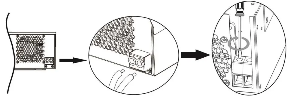 Final Assembly
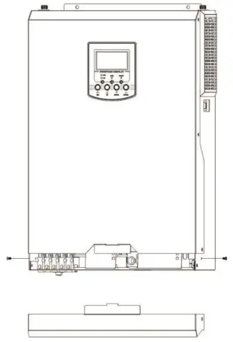
Communication Connection
Please use supplied communication cable to connect to inverter and PC. Insert bundled CD into a computer and follow on-screen instruction to install the monitoring software. For the detailed software operation, please check user manual of software inside of CD.
OPERATION
Power ON/OFF
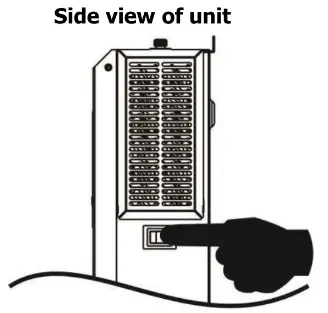
Once the unit has been properly installed and the batteries are connected well, simply press On/Off switch (located on the button of the case) to turn on the unit.
Operation and Display Panel
The operation and display panel, shown in below chart, is on the front panel of the inverter. It includes three indicators, four function keys and a LCD display, indicating the operating status and input/output power information.
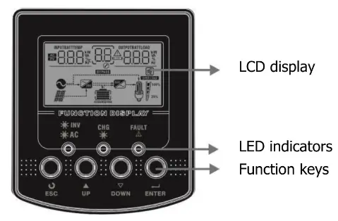
LED Indicator
| LED Indicator | Messages | ||
| Green | Solid On | Output is powered by utility in Line mode. | |
| Flashing | Output is powered by battery or PV in battery mode. | ||
 | Green | Solid On | Battery is fully charged. |
| Flashing | Battery is charging. | ||
| Red | Solid On | Fault occurs in the inverter. | |
| Flashing | Warning condition occurs in the inverter. | ||
Function Keys
| Function Key | Description |
| ESC | To exit setting mode |
| UP | To go to previous selection |
| DOWN | To go to next selection |
| ENTER | To confirm the selection in setting mode or enter setting mode |
LCD Display Icons
![]()
| Icon | Function description |
| Input Source Information | |
| Indicates the AC input. | |
| Indicates the PV input | |
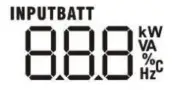 | Indicate input voltage, input frequency, PV voltage, charger current (if PV in charging for 3K models), charger power, battery voltage. |
| Configuration Program and Fault Information | |
 | Indicates the setting programs. |
|
| Indicates the warning and fault codes. Warning:  flashing with warning code. Fault: flashing with warning code. Fault: lighting with fault code lighting with fault code |
| Output Information | |
 | Indicate output voltage, output frequency, load percent, load in VA, load in Watt and discharging current. |
| Battery Information | |
 | Indicates battery level by 0-24%, 25-49%, 50-74% and 75-100% in battery mode and charging status in line mode. |
| In AC mode, it will present battery charging status. | |
| Status | Battery voltage | LCD Display |
| Constant Current mode / Constant Voltage mode
| <2V/cell | 4 bars will flash in turns. |
| 2 ~ 2.083V/cell | Bottom bar will be on and the other three bars will flash in turns. | |
| 2.083 ~ 2.167V/cell | Bottom two bars will be on and the other two bars will flash in turns. | |
| > 2.167 V/cell | Bottom three bars will be on and the top bar will flash. | |
| Floating mode. Batteries are fully charged. | 4 bars will be on. | |
| In battery mode, it will present battery capacity. | ||||||||
| Load Percentage | Battery Voltage | LCD Display | ||||||
|
Load >50% | < 1.85V/cell |  | ||||||
| 1.85V/cell ~ 1.933V/cell |  | |||||||
| 1.933V/cell ~ 2.017V/cell |  | |||||||
| > 2.017V/cell |  | |||||||
|
Load < 50% | < 1.892V/cell | | ||||||
| 1.892V/cell ~ 1.975V/cell | | |||||||
| 1.975V/cell ~ 2.058V/cell | | |||||||
| > 2.058V/cell | | |||||||
| Load Information | ||||||||
 | Indicates overload. | |||||||
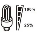 | Indicates the load level by 0-24%, 25-49%, 50-74% and 75-100%. | |||||||
| 0%~24% | 25%~49% | 50%~74% | 75%~100% | |||||
| Mode Operation Information | ||||||||
 | Indicates unit connects to the mains. | |||||||
 | Indicates unit connects to the PV panel. | |||||||
 | Indicates load is supplied by utility power. | |||||||
 | Indicates the utility charger circuit is working. | |||||||
 | Indicates the DC/AC inverter circuit is working. | |||||||
| Mute Operation | ||||||||
 | Indicates unit alarm is disabled. | |||||||
LCD Setting
After pressing and holding ENTER button for 3 seconds, the unit will enter setting mode. Press “UP” or “DOWN” button to select setting programs. And then, press “ENTER” button to confirm the selection or ESC button to exit.
Setting Programs:
| Program | Description | Selectable option | |
| 00 | Exit setting mode | Escape | |
| 01 | Output source priority: To configure load power source priority | Utility first (default) | Utility will provide power to the loads as first priority. Solar and battery energy will provide power to the loads only when utility power is not available. |
Solar first | Solar energy provides power to the loads as first priority. If solar energy is not sufficient to power all connected loads, battery energy will supply power the loads at the same time. Utility provides power to the loads only when any one condition happens: – Solar energy is not available – Battery voltage drops to low-level warning voltage or the setting point in program 12. | ||
SBU priority | Solar energy provides power to the loads as first priority. If solar energy is not sufficient to power all connected loads, battery energy will supply power to the loads at the same time. Utility provides power to the loads only when battery voltage drops to either low-level warning voltage or the setting point in program 12. | ||
| 02 | Maximum charging current: To onfigure total charging current for solar and utility chargers. (Max. charging current = utility charging current + solar charging current) | 10A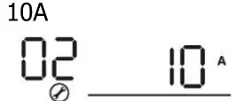 | 20A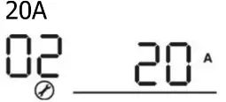 |
30A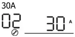 | 40A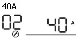 | ||
50A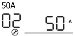 | 60A (default)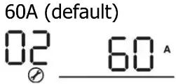 | ||
70A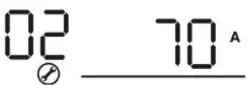 | 80A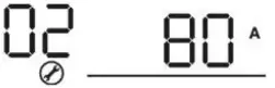 | ||
| 03 | AC input voltage range | Appliances (default) | If selected, acceptable AC input voltage range will be within 90-280VAC. |
UPS | If selected, acceptable AC input voltage range will be within 170-280VAC. | ||
| 05 | Battery type | AGM (default) | Flooded |
User-Defined | If “User-Defined” is selected, battery charge voltage and low DC cut-off voltage can be set up in program 26, 27 and 29. | ||
| 06 | Auto restart when overload occurs | Restart disable (default) | Restart enable |
| 07 | Auto restart when over temperature occurs | Restart disable (default) | Restart enable |
| 09 | Output frequency | 50Hz (default)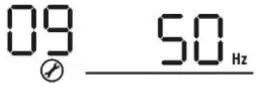 | 60Hz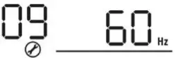 |
| 10 | Output voltage | 220V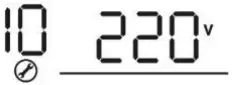 | 230V (default)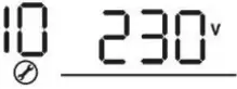 |
240V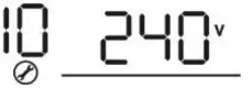 | |||
| 11 | Maximum utility charging current Note: If setting value in program 02 is smaller than that in program in 11, the inverter will apply charging current from program 02 for utility charger. | 2A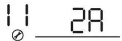 | 10A |
20A | 30A (default) | ||
40A | 50A | ||
60A | |||
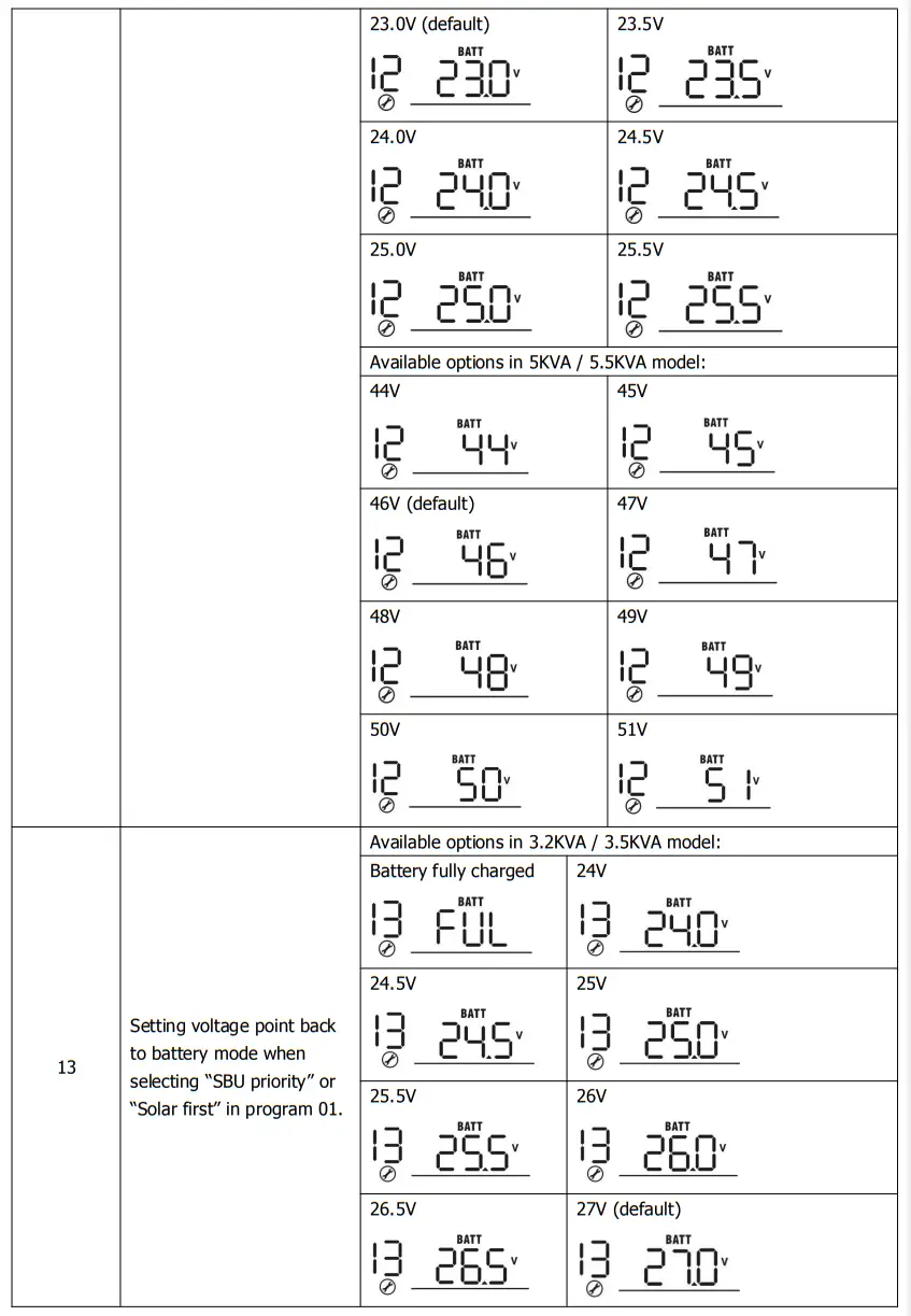
| 12 | Setting voltage point back to utility source when selecting “SBU priority” or “Solar first” in program 01. | Available options in 3.2KVA / 3.5KVA model: | |
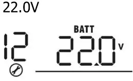 | 22.5V | ||
| 16 | Charger source priority: To configure charger source priority | If this inverter/charger is working in Line, Standby or Fault mode, charger source can be programmed as below: | |
Utility first | Utility will charge battery as first priority. Solar energy will charge battery only when utility power is not available. | ||
Solar first | Solar energy will charge battery as first priority. Utility will charge battery only when solar energy is not available. | ||
Solar and Utility (default) | Solar energy and utility will charge battery at the same time. | ||
Only Solar | Solar energy will be the only charger source no matter utility is available or not. | ||
| If this inverter/charger is working in Battery mode or Power saving mode, only solar energy can charge battery. Solar energy will charge battery if it’s available and sufficient. | |||
| 18 | Alarm control | Alarm on (default) | Alarm off |
| 19 | Auto return to default display screen | Return to default display screen (default) | If selected, no matter how users switch display screen, it will automatically return to default display screen (Input voltage /output voltage) after no button is pressed for 1 minute. |
Stay at latest screen | If selected, the display screen will stay at latest screen user finally switches. | ||
| 20 | Backlight control | Backlight on (default) | Backlight off |
| 22 | Beeps while primary source is interrupted | Alarm on (default) | Alarm off |
| 23 | Overload bypass: When enabled, the unit will transfer to line mode if overload occurs in battery mode. | Bypass disable (default) | Bypass enable |
| 25 | Record Fault code | Record enable (default) | Record disable |
| 26 | Bulk charging voltage (C.V voltage) | 3.2KVA / 3.5KVA default setting: 28.2V | |
5KVA / 5.5KVA default setting: 56.4V | |||
| If self-defined is selected in program 5, this program can be set up. Setting range is from 25.0V to 31.5V for 3.2KVA / 3.5KVA model and 48.0V to 61.0V for 5KVA /5.5KVA model. Increment of each click is 0.1V. | |||
| 27 | Floating charging voltage | 3.2KVA / 3.5KVA default setting: 27.0V | |
5KVA / 5.5KVA default setting: 54.0V | ||||
| If self-defined is selected in program 5, this program can be set up. Setting range is from 25.0V to 31.5V for 3.2KVA / 3.5KVA model and 48.0V to 61.0V for 5KVA /5.5KVA model. Increment of each click is 0.1V. | ||||
| 29 | Low DC cut-off voltage | 3.2KVA / 3.5KVA default setting: 21.0V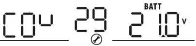 | ||
| 5KVA/5.5KVA default setting: 42.0V
| ||||
| If self-defined is selected in program 5, this program can be set up. Setting range is from 21.0V to 24.0V for 3.2KVA / 3.5KVA model and 42.0V to 48.0V for 5KVA /5.5KVA model. Increment of each click is 0.1V. Low DC cut-off voltage will be fixed to setting value no matter what percentage of load is connected. | ||||
| 30 | Battery equalization | Battery equalization | Battery equalization disable (default) | |
| If “Flooded” or “User-Defined” is selected in program 05, this program can be set up. | ||||
| 31 | Battery equalization voltage | 3.2KVA / 3.5KVA default setting: 29.2V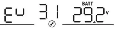 | ||
| 5KVA / 5.5KVA default setting: 58.4V
| ||||
| Setting range is from 25.0V to 31.5V for 3.2KVA /3.5KVA model and 48.0V to 61.0V for 5KVA / 5.5KVA model. Increment of each click is 0.1V. | ||||
| 33 | Battery equalized time | 60min (default)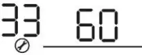 | Setting range is from 5min to 900min. Increment of each click is 5min. | |
| 34 | Battery equalized timeout | 120min (default) | Setting range is from 5min to 900 min. Increment of each click is 5 min. | |
| 35 | Equalization interval | 30days (default) | Setting range is from 0 to 90 days. Increment of each click is 1 day | |
| 36 | Equalization activated immediately | Enable | Disable (default) | |


| If equalization function is enabled in program 30, this program can be set up. If “Enable” is selected in this program, it’s to activate battery equalization immediately and LCD main page will shows “ |
Display Setting
The LCD display information will be switched in turns by pressing “UP” or “DOWN” key. The selectable information is switched as below order: input voltage, input frequency, PV voltage, charging current, charging power, battery voltage, output voltage, output frequency, load percentage, load in Watt, load in VA, load in Watt, DC discharging current, main CPU Version.
| Selectable information | LCD display |
| Input voltage/Output voltage (Default Display Screen) | Input Voltage=230V, output voltage=230V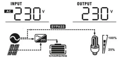 |
| Input frequency | Input frequency=50Hz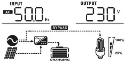 |
| PV voltage | PV voltage=260V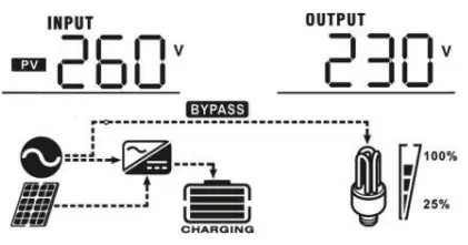 |
| PV current | PV current = 2.5A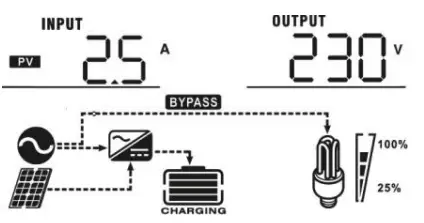 |
| PV power | PV power = 500W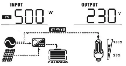 |
| Charging current | AC and PV charging current=50A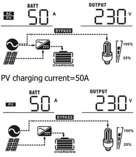 AC charging current=50A 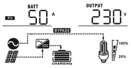 |
| Charging power | AC and PV charging power=500W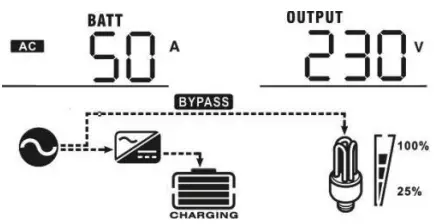 PV charging power=500W PV charging power=500W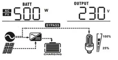 AC charging power=500W AC charging power=500W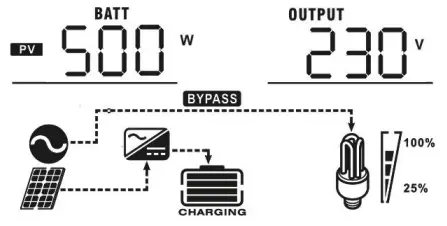 |
| Battery voltage and output voltage | Battery voltage=25.5V, output voltage=230V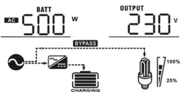 |
| Output frequency | Output frequency=50Hz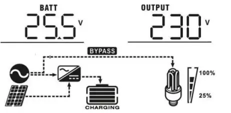 |
| Load percentage | Load percent=70%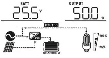 |
| Load in VA | When connected load is lower than 1kVA, load in VA will present xxxVA like below chart.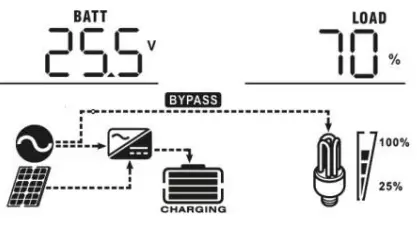 When load is larger than 1kVA (≧1KVA), load in VA will present x.xkVA like below chart. When load is larger than 1kVA (≧1KVA), load in VA will present x.xkVA like below chart.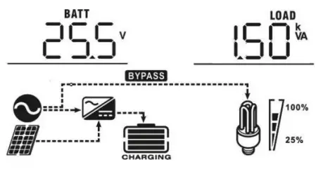 |
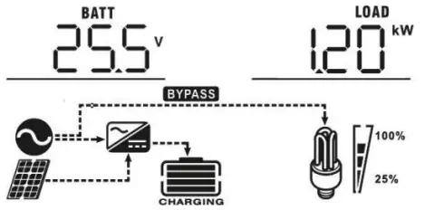
| Load in Watt | When load is lower than 1kW, load in W will present xxxW like below chart.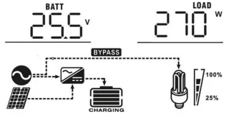 When load is larger than 1kW (≧1KW), load in W will present x.xkW like below chart. When load is larger than 1kW (≧1KW), load in W will present x.xkW like below chart.
|
| Battery voltage/DC discharging current | Battery voltage=25.5V, discharging current=1A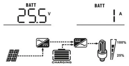 |
| Main CPU version checking | Main CPU version 00014.04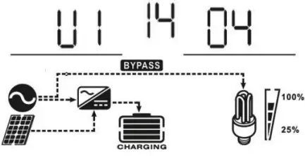 |
Operating Mode Description
| Operation mode | Description | LCD display |
| Standby mode / Power saving mode Note: *Standby mode: The inverter is not turned on yet but at this time, the inverter can charge battery without AC output. *Power saving mode: If enabled, the output of inverter will be off when connected load is pretty low or not detected. | No output is supplied by the unit but it still can charge batteries. | Charging by utility and PV energy.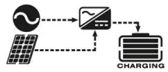 |
Charging by utility.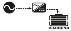 | ||
Charging by PV energy.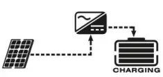 | ||
No charging. | ||
| Fault mode Note: *Fault mode: Errors are caused by inside circuit error or external reasons such as over temperature, outputshort circuited and so on. | PV energy and utility can charge batteries. | Charging by utility and PV energy.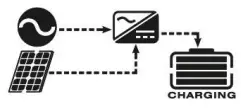 |
Charging by utility.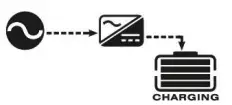 | ||
Charging by PV energy.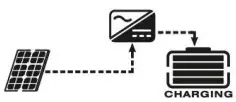 | ||
| No charging. |
| Operation mode | Description | LCD display |
| Line Mode | The unit will provide output power from the mains. It will also charge the battery at line mode. | Charging by utility and PV energy.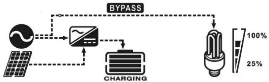 |
| The unit will provide output power from the mains. It will also charge the battery at line mode. | Charging by utility.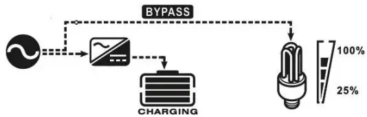 | |
If “solar first” is selected as output source priority and solar energy is not sufficient to provide the load, solar energy and the utility will provide the loads and charge the battery at the same time.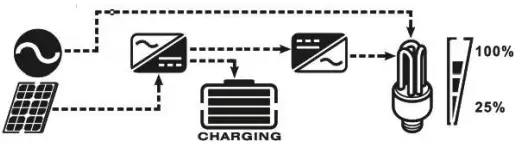 | ||
If “solar first” is selected as output source priority and battery is not connected, solar energy and the utility will provide the loads.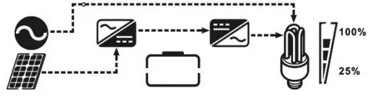 | ||
Power from utility.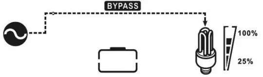 | ||
| Battery Mode | The unit will provide output power from battery and PV power. | Power from battery and PV energy.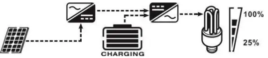 |
PV energy will supply power to the loads and charge battery at the same time.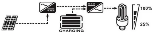 | ||
Power from battery only.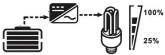 |
| Battery Mode | The unit will provide output power from battery and PV power. | Power from PV energy only.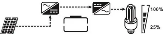 |
Battery Equalization Description
Equalization function is added into charge controller. It reverses the buildup of negative chemical effects like stratification, a condition where acid concentration is greater at the bottom of the battery than at the top. Equalization also helps to remove sulfate crystals that might have built up on the plates. If left unchecked, this condition, called sulfation, will reduce the overall capacity of the battery. Therefore, it’s recommended to equalize battery periodically.
How to Apply Equalization Function
Youmust enable battery equalization function in monitoring LCD setting program 30 first. Then, you may apply this function in device by either one of following methods:
- Setting equalization interval in program 35.
- Active equalization immediately in program 36.
When to Equalize
In float stage, when the setting equalization interval (battery equalization cycle) is arrived, or equalization is active immediately, the controller will start to enter Equalize stage.
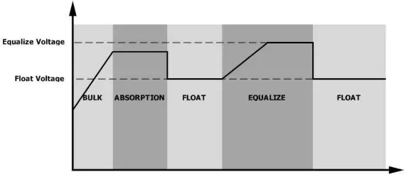
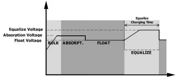
Equalize charging time and timeout
In Equalize stage, the controller will supply power to charge battery as much as possible until battery voltage raises to battery equalization voltage. Then, constant-voltage regulation is applied to maintain battery voltage at the battery equalization voltage. The battery will remain in the Equalize stage until setting battery equalized time is arrived.
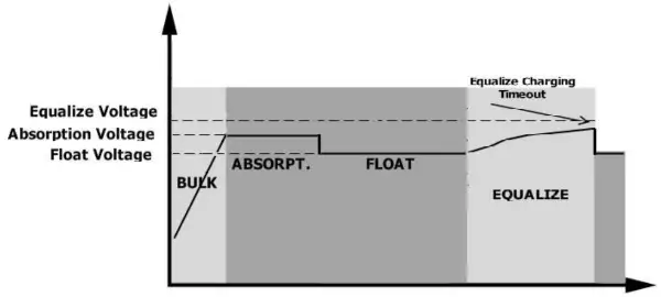
However, in Equalize stage, when battery equalized time is expired and battery voltage doesn’t rise to battery equalization voltage point, the charge controller will extend the battery equalized time until battery voltage achieves battery equalization voltage. If battery voltage is still lower than battery equalization voltage when battery equalized timeout setting is over, the charge controller will stop equalization and return to float stage.
Fault Reference Code
| Fault Code | Fault Event | Icon on |
| 01 | Fan is locked when inverter is off. | 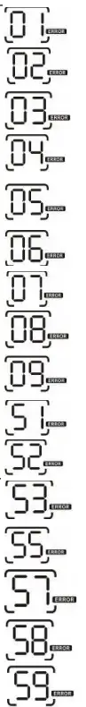 |
| 02 | Over temperature | |
| 03 | Battery voltage is too high | |
| 04 | Battery voltage is too low | |
| 05 | Output short circuited or over temperature is detected by internal converter components. | |
| 06 | Output voltage is too high. | |
| 07 | Overload time out | |
| 08 | Bus voltage is too high | |
| 09 | Bus soft start failed | |
| 51 | Over current or surge | |
| 52 | Bus voltage is too low | |
| 53 | Inverter soft start failed | |
| 55 | Over DC voltage in AC output | |
| 57 | Current sensor failed | |
| 58 | Output voltage is too low | |
| 59 | PV voltage is over limitation |
Warning Indicator
| Warning Code | Warning Event | Audible Alarm | Icon flashing |
| 01 | Fan is locked when inverter is on. | Beep three times every second | 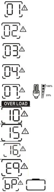 |
| 02 | Over temperature | None | |
| 03 | Battery is over-charged | Beep once every second | |
| 04 | Low battery | Beep once every second | |
| 07 | Overload | Beep once every 0.5 second | |
| 10 | Output power derating | Beep twice every 3 seconds | |
| 15 | PV energy is low. | Beep twice every 3 seconds | |
| 16 | High AC input (>280VAC) during BUS soft start | None | |
| Battery equalization | None | ||
| Battery is not connected | None |
CLEARANCE AND MAINTENANCE FOR ANTI-DUST KIT
Overview
Every inverter is already installed with anti-dusk kit from factory. Inverter will automatically detect this kit and activate internal thermal sensor to adjust internal temperature. This kit also keeps dusk from your inverter and increases product reliability in harsh environment.
Clearance and Maintenance
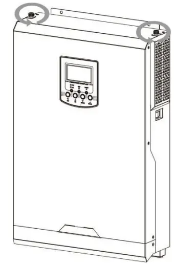
Step 1: Please loosen the screw in counterclockwise direction on the top of the inverter.
 Step 2: Then, dustproof case can be removed and take out air filter foam as shown in below chart.
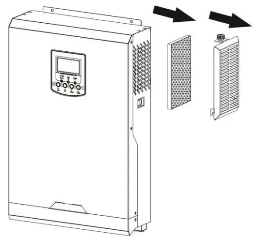 Step 3: Clean air filter foam and dustproof case. After clearance, re-assemble the dust-kit back to the inverter.
NOTICE: The anti-dust kit should be cleaned from dust every one month.
SPECIFICATIONS
Table 1 Line Mode Specifications
| INVERTER MODEL | 3.2KVA | 3.5KVA | 5KVA | 5.5KVA |
| Input Voltage Waveform | Sinusoidal (utility or generator) | |||
| Nominal Input Voltage | 230Vac | |||
| Low Loss Voltage | 170Vac±7V (UPS); 90Vac±7V (Appliances) | |||
| Low Loss Return Voltage | 180Vac±7V (UPS); 100Vac±7V (Appliances) | |||
| High Loss Voltage | 280Vac±7V | |||
| High Loss Return Voltage | 270Vac±7V | |||
| Max AC Input Voltage | 300Vac | |||
| Nominal Input Frequency | 50Hz / 60Hz (Auto detection) | |||
| Low Loss Frequency | 40±1Hz | |||
| Low Loss Return Frequency | 42±1Hz | |||
| High Loss Frequency | 65±1Hz | |||
| High Loss Return Frequency | 63±1Hz | |||
| Output Short Circuit Protection | Circuit Breaker | |||
| Efficiency (Line Mode) | >95% ( Rated R load, battery full charged ) | |||
| Transfer Time | 10ms typical (UPS); 20ms typical (Appliances) | |||
| Output power derating: When AC input voltage drops to 170V, the output power will be derated. | 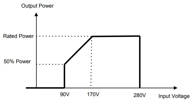 | |||
Table 2 Inverter Mode Specifications
| INVERTER MODEL | 3.2KVA | 3.5KVA | 5KVA | 5.5KVA |
| Rated Output Power | 3.2KVA/3.2KW | 3.5KVA/3.5KW | 5KVA/5KW | 5.5KVA/5.5KW |
| Output Voltage Waveform | Pure Sine Wave | |||
| Output Voltage Regulation | 230Vac±5% | |||
| Output Frequency | 50Hz | |||
| Peak Efficiency | 93% | |||
| Overload Protection | 5s@≥150% load; 10s@110%~150% load | |||
| Surge Capacity | 2* rated power for 5 seconds | |||
| Nominal DC Input Voltage | 24Vdc | 48Vdc | ||
| Cold Start Voltage | 23.0Vdc | 46.0Vdc | ||
| Low DC Warning Voltage @ load < 50% @ load ≥ 50% | 23.0Vdc 22.0Vdc | 46.0Vdc 44.0Vdc | ||
| Low DC Warning Return Voltage @ load < 50% @ load ≥ 50% | 23.5Vdc 23.0Vdc | 47.0Vdc 46.0Vdc | ||
| Low DC Cut-off Voltage @ load < 50% @ load ≥ 50% | 21.5Vdc 21.0Vdc | 43.0Vdc 42.0Vdc | ||
| High DC Recovery Voltage | 32Vdc | 62Vdc | ||
| High DC Cut-off Voltage | 33Vdc | 63Vdc | ||
| No Load Power Consumption | <35W | |||
Table 3 Charge Mode Specifications
| Utility Charging Mode | |||||
| INVERTER MODEL | 3.2KVA | 3.5KVA | 5KVA | 5.5KVA | |
| Charging Algorithm | 3-Step | ||||
| AC Charging Current (Max) | 60Amp (@VI/P=230Vac) | ||||
| Bulk Charging Voltage | Flooded Battery | 29.2 | 58.4 | ||
| AGM/Gel Battery | 28.2 | 56.4 | |||
| Floating Charging Voltage | 27Vd | 54Vdc | |||
| Charging Curve | 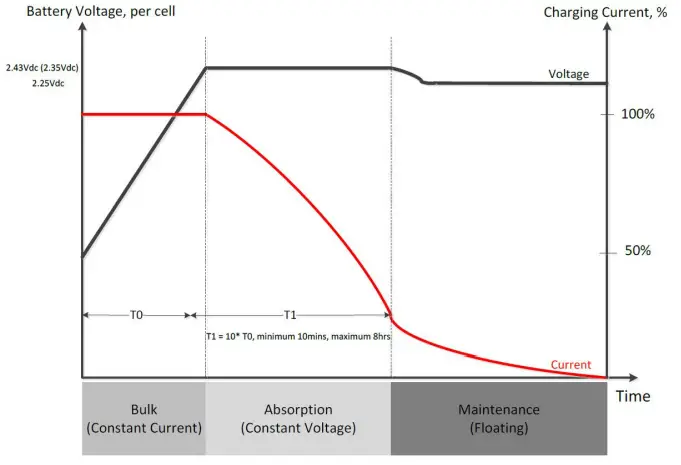 | ||||
| MPPT Solar Charging Mode | |||||
| INVERTER MODEL | 3.2KVA | 3.5KVA | 5KVA | 5.5KVA | |
| Max. PV Array Power | 4000W | 5000W | 5000W | 6000W | |
| Nominal PV Voltage | 240Vdc | ||||
| Start-up Voltage | 150Vdc +/- 10Vdc | ||||
| PV Array MPPT Voltage Range | 120~450Vdc | ||||
| Max. PV Array Open Circuit Voltage | 500Vdc | ||||
| Max Charging Current (AC charger plus solar charger) | 80Amp | 100Amp | 80Amp | 100Amp | |
Table 4 General Specifications
| INVERTER MODEL | 3.2KVA | 3.5KVA | 5KVA | 5.5KVA |
| Safety Certification | CE | |||
| Operating Temperature Range | -10°C to 50°C | |||
| Storage temperature | -15°C~ 60°C | |||
| Humidity | 5% to 95% Relative Humidity (Non-condensing) | |||
| Dimension (D*W*H), mm | 115 x 300 x 440 | |||
| Net Weight, kg | 9 | 9 | 10 | 10 |
TROUBLE SHOOTING
| Problem | LCD/LED/Buzzer | Explanation / Possible cause | What to do |
| Unit shuts down automatically during startup process. | LCD/LEDs and buzzer will be active for 3 seconds and then complete off. | The battery voltage is too low (<1.91V/Cell) | 1. Re-charge battery. 2. Replace battery. |
| No response after power on. | No indication. | 1. The battery voltage is far too low. (<1.4V/Cell) 2. Internal fuse tripped. | 1. Contact repair center for replacing the fuse. 2. Re-charge battery. 3. Replace battery. |
| Mains exist but the unit works in battery mode. | Input voltage is displayed as 0 on the LCD and green LED is flashing. | Input protector is tripped | Check if AC breaker is tripped and AC wiring is connected well. |
| Green LED is flashing. | Insufficient quality of AC power. (Shore or Generator) | 1. Check if AC wires are too thin and/or too long. 2. Check if generator (if applied) is working well or if input voltage range setting is correct. (UPSàAppliance) | |
| Green LED is flashing. | Set “Solar First” as the priority of output source. | Change output source priority to Utility first. | |
| When the unit is turned on, internal relay is switched on and off repeatedly. | LCD display and LEDs are flashing | Battery is disconnected. | Check if battery wires are connected well. |
| Buzzer beeps continuously and red LED is on. | Fault code 07 | Overload error. The inverter is overload 110% and time is up. | Reduce the connected load by switching off some equipment. |
| If PV input voltage is higher than specification, the output power will be derated. At this time, if connected loads is higher than derated output power, it will cause overload. | Reduce the number of PV modules in series or the connected load. | ||
| Fault code 05 | Output short circuited. | Check if wiring is connected well and remove abnormal load. | |
| Temperature of internal converter component is over 120°C. | Check whether the air flow of the unit is blocked or whether the ambient temperature is too high. | ||
| Fault code 02 | Internal temperature of inverter component is over 100°C. | ||
| Fault code 03 | Battery is over-charged. | Return to repair center. | |
| The battery voltage is too high. | Check if spec and quantity of batteries are meet requirements. | ||
| Fault code 01 | Fan fault | Replace the fan. | |
| Fault code 06/58 | Output abnormal (Inverter voltage below than 190Vac or is higher than 260Vac) | 1. Reduce the connected load. 2. Return to repair center | |
| Fault code 08/09/53/57 | Internal components failed. | Return to repair center. | |
| Fault code 51 | Over current or surge. | Restart the unit, if the error happens again, please return to repair center. | |
| Fault code 52 | Bus voltage is too low. | ||
| Fault code 55 | Output voltage is unbalanced. | ||
| Fault code 59 | PV input voltage is beyond the specification. | Reduce the number of PV modules in series. |
Appendix: Approximate Back-up Time Table
| Model | Load (VA) | Backup Time @ 24Vdc 100Ah (min) | Backup Time @ 24Vdc 200Ah (min) |
| 3.2KVA/3.5KVA | 300 | 449 | 1100 |
| 600 | 222 | 525 | |
| 900 | 124 | 303 | |
| 1200 | 95 | 227 | |
| 1500 | 68 | 164 | |
| 1800 | 56 | 126 | |
| 2100 | 48 | 108 | |
| 2400 | 35 | 94 | |
| 2700 | 31 | 74 | |
| 3000 | 28 | 67 |
| Model | Load (VA) | Backup Time @ 48Vdc 100Ah (min) | Backup Time @ 48Vdc 200Ah (min) |
| 5KVA/5.5KVA | 500 | 613 | 1288 |
| 1000 | 268 | 613 | |
| 1500 | 158 | 402 | |
| 2000 | 111 | 271 | |
| 2500 | 90 | 215 | |
| 3000 | 76 | 182 | |
| 3500 | 65 | 141 | |
| 4000 | 50 | 112 | |
| 4500 | 44 | 100 | |
| 5000 | 40 | 90 |
Note: Backup time depends on the quality of the battery, age of battery and type of battery. Specifications of batteries may vary depending on different manufacturers.
![]()


