 EXPERT POWER IVOCH2KW 12V Inverter Charger
 WARNING
PLEASE READ THE INSTRUCTIONS BEFORE CONTINUING
This manual contains important safety installation and operation instructions for the ExpertPower Inverter-Charger. Please do not operate the Inverter-Charger without reading this manual first.
General Information
Safety Information and Warnings
Before designing and during production, the safety of the consumer and product have all been considered. Please follow the user instructions carefully to operate or install the machine to prevent injury or accident. Please keep this manual for future reference.
- The installation of the inverter should be done by professionals or under the assistance of a local dealer.
- Verify whether the input DC voltage range meets voltage polarity requirements (12V±20%). Confirm whether the load device voltage is single-phase 100V ~ 120VAC; power should not be more than rated output power of the inverter.
- Do not spill any liquid on the inverter, or use a damp cloth to wipe the inverter casing. Do not touch the unit’s terminals when running– especially with wet hands, otherwise electric shock injury will occur.
- If you need to change the working environment, do not do so yourself. It should be done by professionals or with assistance from the supplier/local dealer.
- The operating environment of the inverter should be well-ventilated. Temperature range is – 4 to 113°F. Keep away from fuel sources and direct sunlight. Do not run in humid or dusty environments. During operation, high temperatures are normal. To maintain proper ventilation, please keep a clean environment around the unit. Do not allow any vents be blocked.
- Keep children away from this unit at all times. It is not a toy. Serious injury or death could occur.
- Confirm if the inverter can be connected with existing wiring. The AWG rating should be
sufficient for the loads that will be ran. - Do not open the inverter under any circumstances. Besides voiding the warranty, you are risking severe electric shock to yourself and others around you.
Introduction
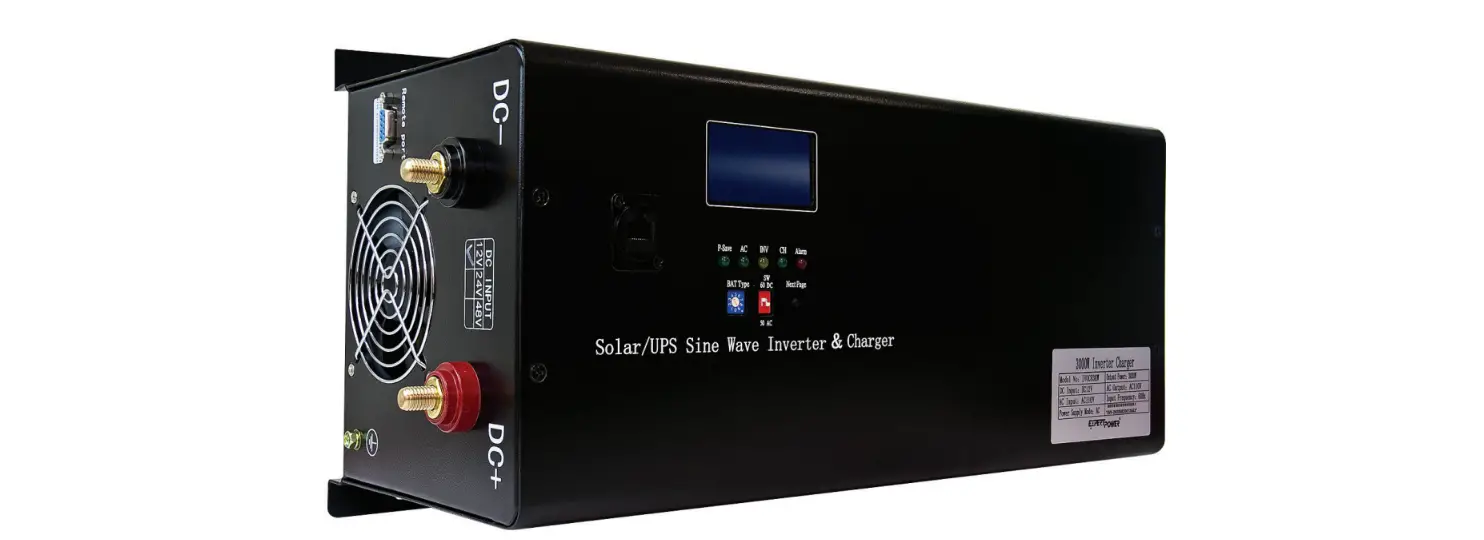
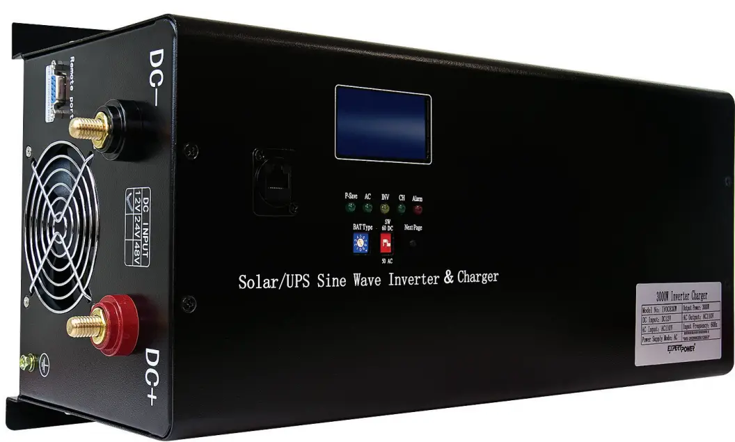
ExpertPower Inverter-Charger
The inverter is pure sine-wave with an on-board intelligence system that handles most of the heavy lifting within your electrical system. The inverter converts 12 volt direct current (VDC) into 110 volt alternating current (VAC), or more commonly, the power you utilize at home through your wall outlets. A typical solar power system consists of a solar panel, solar charge controller, inverter, battery, and components such as fuses and breakers.
This inverter has a bypass feature allowing you to use it WITH OR WITHOUT batteries meaning you can depend solely on shore-power for your AC and DC appliances.
Core advantages of the inverter:
- CPU intelligent management
- Latest American technical inverter
- Best electric components
- High conversion efficiency( 90%~99%)
Applications
| Home Power Tools | Circular saws, drills, grinders, sanders, buffers, weed and hedge trimmers, air compressors |
| Office Equipment | Computers, printers, monitors, scanners |
| Household Items | Vacuum cleaners, fans, fluorescent and incandescent lights, shavers, sewing machines |
| Kitchen Appliances | Coffee makers, blenders, ice markers, toasters |
| Industrial Equipment | Metal halide lamp, high – pressure sodium lamp |
| Home Entertainment | Television, Blue-ray player, video games, stereos, musical instruments, satellite equipment |
Diagram
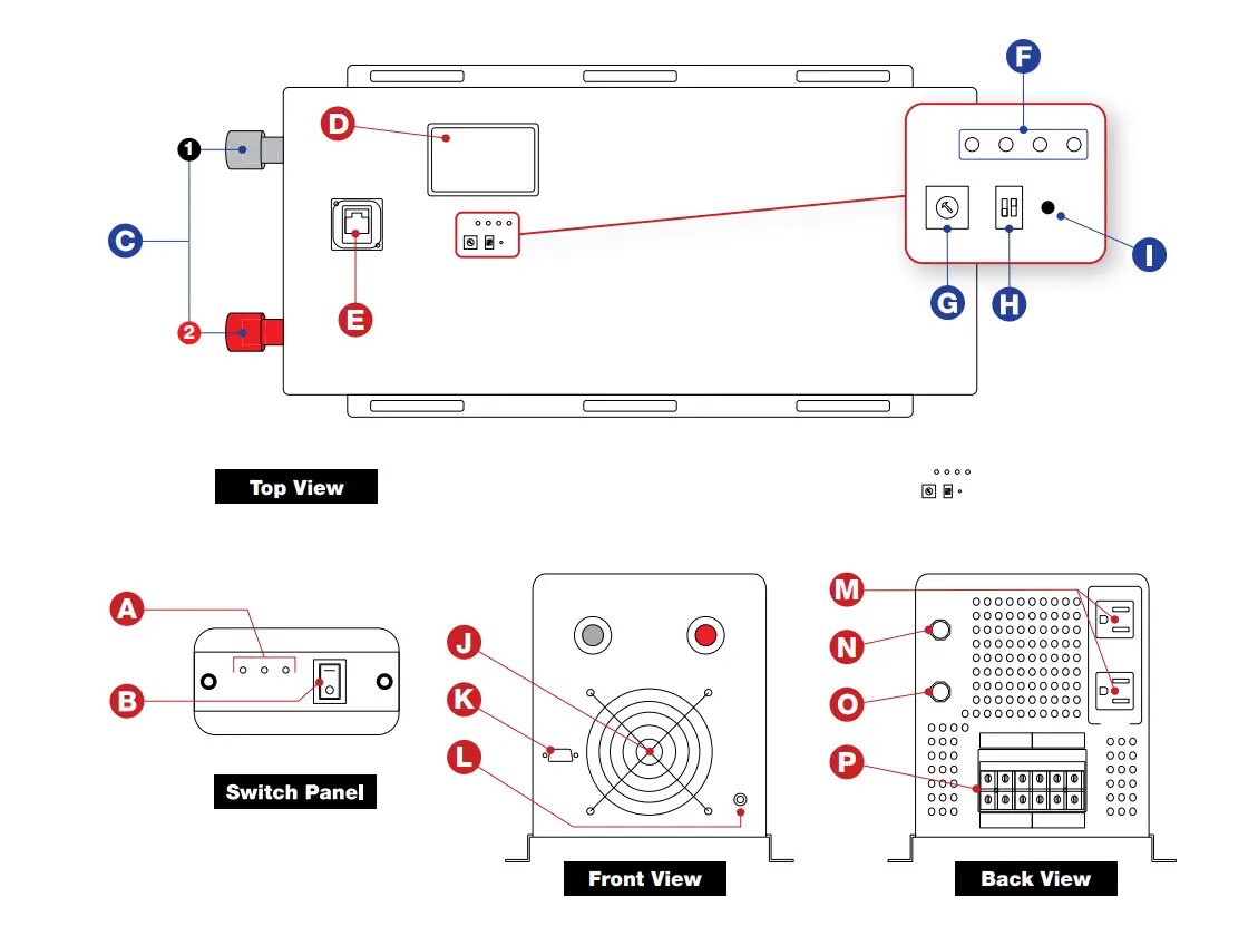
- On/Off Switch
- Panel LEDs
- Terminals:
- Negative (-)
- Positive (+)
- LCD Screen
- Interface Panel Port
- Status LEDs
- Battery Type Multi-Switch
- 50Hz/60Hz Switch & Priority Modes
- Next Page Button
- Fan
- Communication Port
- Grounding Terminal
- AC Ports
- Inverter Output Protection
- Charger Input Protection
- AC Terminal
Technical Specs
Utility Model Specifications
| AC110V | |
| Efficiency | 2:98% |
| Input Wave Type | Pure Sine Wave |
| Input Voltage Range | AC 75V-135V |
| Nominal Input Voltage | 110Vac |
| Low Voltage shutoff | 92Vac±4% |
| Low Voltage Recovery | 97Vac ±4% |
| Over voltage Shut off | 127Vac±4% |
| Over Voltage Recovery | 122Vac±4% |
| Nominal Input Frequency | 50Hz/60Hz (auto detect) |
| Output Wave Type | Pure Sine Wave |
| Transfer Time (AC to DC) | <5ms |
| Transfer Time (DC to AC) | <5ms |
Inverter Mode Specification
| Power Factor | 1 (Sufficient output power) | |
| Model Number | IVOCH2KW | IVOCH3KW |
| Continuious Power | 2000W | 3000W |
| Surge Power (1 Second) | 6000W | 9000W |
| Rated Input Voltage (V) | 12Vdc | |
| Rated Output Voltage (V) | 110Vac | |
| Nominal Output Frequency (Hz) | 50/60 ± 0.3Hz | |
| Output Voltage Range | ±10% rms | |
| Efficiency | >90% DC12V | |
| No Load Power Consumption | 3% of Power Rating | |
|
Overload Protection | (110%<1oad<125%) ±10%: Shutdown after 15 minutes; (125%<Ioad<150%) ±10%: Shutdown after 60s; Load>150% ±10%: Shutdown after 20s | |
| Low Battery Alarm | 10.5Vdc ± 0.3Vdc (12V Input) | |
| Low DC input voltage automatic shut-down | 10.0Vdc ± 0.3Vdc (12V Input) | |
| High DC input voltage warning, then shut down | 16Vdc ± 0.3Vdc (12V Input) | |
| High DC input voltage Recover | 15.5Vdc ± 0.3Vdc (12V Input) | |
| Safety | CE/EMC | |
| Communication port | RS232 | |
| Cooling | Variable Fan According to Temperature | |
| Operating Temperature Range | 32′ F to 140′ F | |
| Storage temperature | 5′ F – 140′ F | |
| Humidity | 5% to95% | |
| Noise | Max 60dB | |
Basic Connection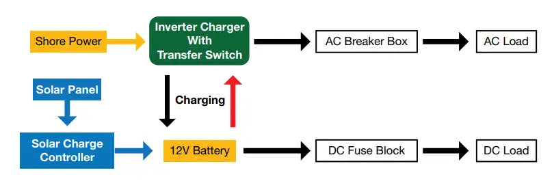
-This inverter charger is an essential part of any electrical system in an RV or camper. It’s vital that the inverter works in unison with the rest of your system without conflict. Below is a typical example of what the electrical system is like. Shore power flows through the inverter-charger to provide AC power guarded by breakers or fuses while charging the battery bank. The same concept applies while under battery power, as the inverter will be powered by DC (battery) and then converted to AC while protected with battery specific fuses and breakers. The battery can be charged utilizing solar panels that flow into a solar charger controller to provide usable power.
Auto Transfer Switch Priority Mode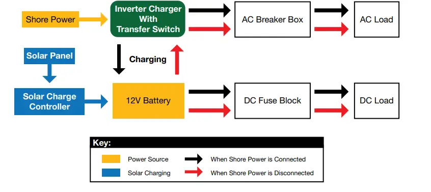
Priority Mode Selection (select on the front panel)
AC Priority
When set to AC priority, you will draw from shore power and not the battery bank. When not connected to shore power, DC power from the battery bank/solar will be converted into AC.
- When shore power is connected, it will be utilized over the battery bank to power the inverter while simultaneously charging the battery bank. Charging can be turned off by setting Battery Type switch to 0. (See page 10)
- When shore power is disconnected, the inverter automatically switches to solar/battery bank power in 5ms.
- When shore power is restored, the inverter will automatically switch the power source from battery bank to shore power in 5 ms.
DC Priority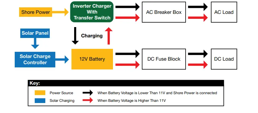
When set to DC priority, the inverter will utilize the battery bank for electricity. When battery voltage gets too low, it will automatically switch to shore power. Charging can be turned off by setting battery switch to 0. (See Page 10)
- AC and DC loads will be powered by the battery with the inverter if battery voltage is higher than 11V.
- When battery voltage drops below 11V, the inverter automatically switches to shore power (if connected) and charges the batteries.
- When battery is charged to 13.5V, the inverter will automatically switch back to battery power.
- When shore power is not detectable and battery voltage is lower than 10V, the inverter will shut down. When shore power is detected again, the inverter will turn on automatically and switch to shore power and charge the battery or when battery is charged to 12V (solar), inverter will automatically turn on and switch to battery power.
Charger
Information Table
| MODEL
| SPECIFICATON | |
| 2KW | 3KW | |
| DC voltage level | 12V | 12V |
| Charging current | 35A | 50A |
| MATCHING | ||
| Theoretical charge voltage | According to the battery type | |
| CHARGING CIRCET PROTECTION | Circuit breaker protection | |
| CHARGING RULES | Lithium Battery: constant current charging (constant current stage) -> constant voltage (constant voltage stage) -> float (constant current stage) | |
|
Charging-stage
| constant current charging stages: input AC grid, the charger will run until to the constant voltage stage of maximum rated current. constant voltage charging stage: The charger will keep the mode of constant voltage , then the voltage drops to float voltage. The minimum time is one hour, the maximum time is 12 hours. – floating stage: at the floating stage, the voltage will keep the float voltage. – If you re-connect the AC, the charger will recycle the steps of above when the battery voltage drops below 12Vdc – If the Chargers keep floating state for 10 days, the charger will restart the L cycle | |
Top Panel Settings
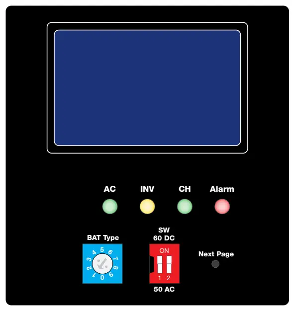
Panel Overview
| SHORE POWER ON | AC LED lights GREEN | |
| INV (Inverter) | INVERTER LED lights up YELLOW to indicate it’s on. | |
| CH (Charger) | CH LED lights GREEN for bulk/float charging | |
| ALARM | Alarm LED lights up RED | |
| BAT Type | Battery Type 1-9 Selector | |
| SW (Working Mode) | Frequency Selection | Adjust frequency between “50Hz” and “60Hz” |
| AC/DC Switch | Adjust the AC/DC power priority | |
| Next Page | Move to the next page in the information panel | |
Battery Type Selections and SW Switch
Different kinds of batteries have varying charging voltages. In order to protect your batteries, our inverter is designed to be suitable for a variety of different types of batteries. On the top of the inverter, you can choose the correct voltage specific to your needs using the BAT Type Dial and the Gear Set Table below to ensure that your battery is with in optimal condition.
Using the Battery Type Dial: 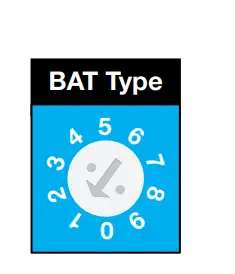
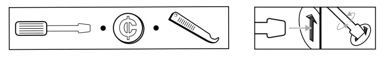
- To move the dial use a small screwdriver, coin, or other flat tool and insert it into the arrow shown on the left. Turn the screwdriver so that the arrow in the BAT Type Dial points to the desired Switch Setting shown below.
- Gear Set TablE
| Switch Setting | Description | Boost | Float |
| Voltage | Voltage | ||
| 12V | 12V | ||
| 0 | FACTORY DEFAULT | Not charging | Not charging |
| 1 | Gel USA | 14.0 | 13.7 |
| 2 | AGM 1 | 14.1 | 13.4 |
| 3 | AGM 2 | 14.6 | 13.7 |
| 4 | Sealed Lead Acid | 14.4 | 13.6 |
| 5 | Lithium (LiFePO4) | 14.4 | 13.8 |
| 6 | Open lead acid | 14.8 | 13.3 |
| 7 | Calcium | 15.1 | 13.6 |
| 8 | Desulphation | 15.5 | 4 hours then off |
| 9 | Not used | – | – |
Using the SW Switch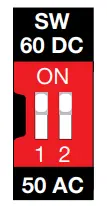
Use your fingernail, pen, or small enough object to change the switches to the desired priority.
- SW 1:
Move to “ON” to set frequency to 60Hz. For 50Hz, set the switch back down. - SW 2:
Move to “ON” to set priority to “DC”. For AC priority, set the switch back down.
WARNING:The output voltage of this unit must never be connected in its input AC terminal, overload or damage may result. Always switch on the inverter before plugging in any appliance.
AC Wiring Connection
120V Single Phase
We recommend using 10-12AWG wire to connect to the AC terminal block. There is only one way of connecting and wiring the terminal block. All of the wirings are CE compliant. Please contact our technical support team if you are not sure about how to wire any part of your inverter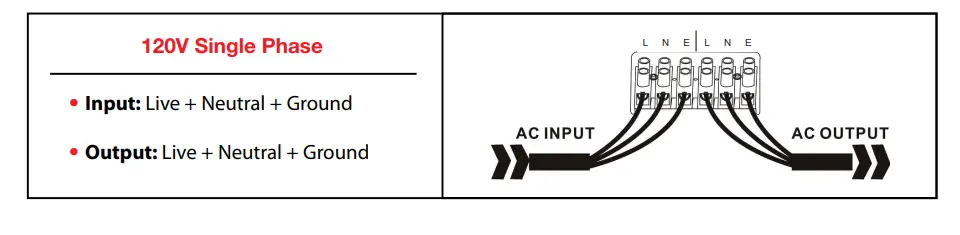
DC Wiring Connection
Cable Type Selections
It is suggested the battery bank be kept as close as possible to the inverter. The following table is a suggested wiring guide for a 1 meter cable. In case of wiring longer than 1m, please increase the cross section of cable to reduce the loss.
| Watt Model | Battery Voltage | Wire Gauge / Min | Watt Model | Battery Voltage | Wire Gauge / Min | ||
| 0~1.0m | 1.0~5.0m | 0~1.0m | 1.0~5.0m | ||||
| 2000 | 12 Vdc | 60mm2 | 75mm2 | 3000 | 12 Vdc | 90mm2 | 120mm2 |
- Please note that if there is a problem obtaining for example 90mm˛ cable, use 2*50mm˛ or 3*35mm˛.
- One cable is always best, but cable is simply copper and all you require is the copper, so it does not matter if it is one cable or 10 cables as long as the square area adds up. Performance of any product can be improved by thicker cable and shorter runs, so if in doubt round up and keep the length as short as possible.
Audible Alarm Protection
Alarm Indicators
| Indicator | |
| Battery Voltage Low | Inverter LED lights green and buzzer beeps every 5s |
| Battery Voltage High | Inverter LED lights green and buzzer beeps every 1s — shuts down after 60s |
| Inverter Overload | 110%< load<125%: No audible alarm for 14 minutes, Begins to beep every second at the start of the 15th minute, and shuts down after 15 minutes. 125% <load<150%: Beeps every 1s, and shuts down after 60s. Load>150%: Beeps every 1s, and shuts down after 20s. |
| Over-Temperature | Heat sink temp. >105ºC, over temp. red LED Light flashes, beeps every 1s; |
Fan
| Protection | |
| Over Temperature Protection | Heat sink temp. 105ºC, (shutdown) after 30 seconds |
| Back-Feed Protection | Yes |
| Recover from shutting down for fault | Mode of operation: restart the machine |
LED Indicatiors & Error Codes
LCD Display
LCD Will Display as Follows: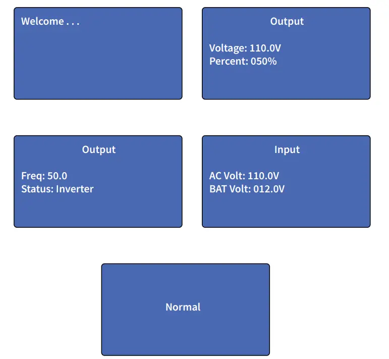
Error Codes
Fault Status Description: Fault: TX 0000000 “TX” means the load and inverter do not connect, an internal line connection failure. For more detailed information on fault status, please refer to Fault Status Table. The inverter will display “System Normal” when working.
Fault Status Table
| site | Name | ||
| B0 | Communication Failure | 0- normal 1- failure | TX 0000000 |
| B1 | Battery Voltage | 0- normal 1- failure | 1000000 |
| B2 | Inverter Failure | 0- normal 1- failure | 0100000 |
| B3 | Fan Failure | 0- normal 1- failure | 0010000 |
| B4 | Output Overload | 0- normal 1- failure | 0001000 |
| B5 | Output Short Circuit | 0- normal 1- failure | 0000100 |
| B6 | Battery Failure | 0- normal 1- failure | 0000010 |
| B7 | Battery Over-Voltage | 0- normal 1- failure | 0000001 |
Troubleshooting for Audible and Visual Indicators
LCD, LED Indicator, & Buzzer Table
|
Status |
Item | SHORE POWER ON |
INVERTER | BATTERY CHARGER |
ALARM |
BUZZER |
|
Line Mode | CC | |||||
| CV | ||||||
| Float | ||||||
| Standby | ||||||
| Invert Mode | Inverter On | |||||
|
Alarm Mode | Battery Low | Beeps Every 5s | ||||
| Battery High | Beeps Every 1s | |||||
| Overload on Invert Mode | Refer to “Audible alarm” | |||||
| Over-Temperature on Invert Mode | Continuous Beep | |||||
| Over-Temperature on Utility Line Mode | Continuous Beep | |||||
| Overcharge | Continuous Beep | |||||
|
Fault Mode | Fan Lock | Continuous Beep | ||||
| Battery High | Continuous Beep | |||||
| Inverter Mode Overload | Continuous Beep | |||||
| Over-Temperature | Continuous Beep | |||||
| Overcharge | Continuous Beep | |||||
| Back Feed Short | Continuous Beep |


