![]() CN100 CAP NAILER
CN100 CAP NAILER
OWNER’S MANUAL

CN100 15 Degree 1 In Cap Nailer
![]() PLEASE READ!
PLEASE READ!
This manual contains important information about product safety.
IMPORTANT INFORMATION
Please take the time to read and understand the information contained in the Owner’s Manual included with this product before operating or maintaining the STINGER CN100 Cap Nailer.
Improper use of this tool could result in serious injury or even death. Most accidents occur because of the failure to observe basic safety rules and precautions. Basic safety precautions are
outlined in the “Warnings” section of this manual.
This product is intended for securing synthetotic underlayments, roofing felt and housewraps.
 WARNINGS
PERSONAL SAFETY ITEMS
- Reading the Owner’s Manual prior to using the tool.
 Always wear eye protection that conforms to ANSI requirements (Z87.1) and provides protection against flying particles both from the front and side. Eye protection should be worn by the operator and by others in the work area to protect against flying fasteners and debris that could possibly cause severe eye injury.
- The employer is responsible for enforcing the use of eye protection equipment by the tool operator and all other personnel in the work area.
- To prevent accidental injuries:
- Handle the tool with care
- Always assume that the tool contains fasteners
- Always disconnect the air hose from the STINGER CN100 when:
- loading nails and/or caps
- performing inspection, maintenance or repair
- clearing a nail or collated cap jam
- the tool is not in use
- leaving the work area
- moving the STINGER CN100 to another work location
- handing the STINGER CN100 to another person
- storing the tool
- Never point the tool toward yourself or anyone else
- Never engage in horseplay when handling the tool
- Never hold or carry the tool with a finger on the trigger
- Never place a hand or any other part of the body in the fastener discharge area of the tool while the air supply is connected
AIR SUPPLY AND CONNECTIONS
- Use only clean, regulated compressed air as a power source for this tool. Do not use bocle gases, combus%ble gases or oxygen as a power source for the tool as the tool may explode.
- Do not use air supply pressures that exceed 105 PSI.
- Do not exceed the recommended maximum operating air pressure as tool wear will be greatly increased. The air supply must be capable of maintaining the operating air pressure of the tool.
Pressure drops in the air supply can reduce the tool’s driving power. - Use a pressure regulator and gauge to allow visual inspection of the air pressure being delivered to the tool.
- Use air hoses that have rated pressures of up to 150fi of the maximum pressure that can be generated by the power source. The supply hose should contain 1/4” figngs that will provide quick disconnecting from the male plug on the tool.
- Use quick connect figngs that allow the tool to be unhooked from the air supply quickly and easily.
- Do not use figngs that will not allow the tool to exhaust when the air supply is disconnected.
OPERATION OF THE TOOL
- Never inspect, maintain, repair, adjust, clear a jam or store the tool with the air connected.
- Never use the tool in proximity of flammable gases or liquids, as some tools will create sparks that can be an ignition source for a fire or explosion.
- Always inspect the safety device for damage and proper operation, prior to operation.
- Never assume the tool is empty of fasteners.
- Never point the tool toward yourself or any other persons.
- Never cycle the tool unless it is in contact with the work‐piece.
- Never use the tool as a hammer or wedging device or drop to the floor from any height.
- Always remove your finger from the trigger when pausing from cycling.
- Never tamper with the safety device or use the tool if the safety device is not functioning properly.
- Use only 1” STINGER NailPac® cap nails with the STINGER CN100 Cap Nailer. Never use any fasteners that are not specified for use in this tool. The CN100 holds 1 roll of plastic caps (200 caps) and 1 coil of nails (200 nails each).
TOOL SPECIFICATIONS
| Operating pressure | 95‐105 psi |
| Weight | 4.9 lb. |
| Nail capacity | 200 nails (1‐200 count coil) |
| Cap capacity | 200 plas%c collated caps (1‐200 count roll) |
| Air inlet | 1/4” |
| Fasteners | STINGER NailPac® (National Nail product number 136260) includes 10 coils of 1” EG ring shank nails (200 nails per coil) and 10 rolls of 1” diameter plastic collated caps (200 caps per roll). |
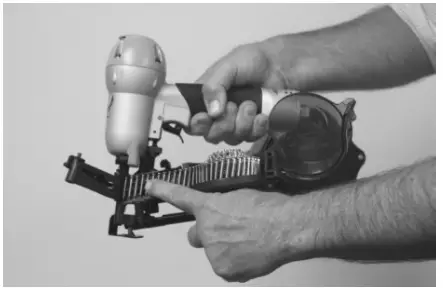
LOADING THE TOOL
USE 1” STINGER NAILPAC® CAP NAILS ONLY
- Disconnect air.
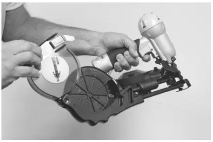
- Open the cap magazine cover by pushing the green cover release tab and liling.

- Place cap roll in basket. Make sure the front end of the cap roll is placed over the cap guide area of the basket. Insert lead cap into the feed chute.
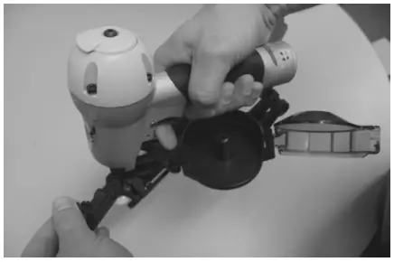
- Slide caps along the feed chute with fingers until they engage the cap feeder. Pull the cap feeder back and release to advance caps until the first cap is under the nose of the tool.
- Close the magazine cover.

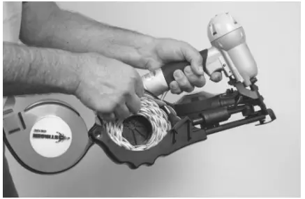
- Depress the latch on the nail gate and basket cover. Open nail gate. Open nail basket cover. Place one nail coil in basket so it fits securely around center post.

- Insert lead nail into nose. Lay following nails flat onto feeder pawls.
- Close nail basket cover. Close nail gate. Be sure latch is securely fastened.
- Plug into air source. Tool is ready to use.
OPERATING THE TOOL
- Read the Owner’s Manual prior to using the tool.
- Read warning label(s) on the tool.
- Visually inspect the tool for worn or damaged parts.
- Wear appropriate eye protection.
- Insert a male pneumatic figng into the end cap of the tool, ensuring that the figng allows the tool to exhaust any air in the tool when the air hose is disconnected.
- Add 2 drops of non‐detergent, 20‐weight oil into the male figng daily.
- Connect the air hose using a quick connect figng to the tool, and check the air pressure reading on the regulator to ensure it does not exceed 105 PSI. Check the tool for any air leaks.
- Place the tool, empty of fasteners, in opera%ng position on a scrap work piece. Fully depress the safety and pull the trigger to verify the tool cycles.
- Disconnect the air hose from the tool when:
• Loading nails and/or caps
• Performing inspection, maintenance or repair
• Clearing a nail or collated cap jam
• The tool is not in use
• Leaving the work area
• Moving the tool to another work location
• Handing the STINGER CN100 to another person
• Storing the tool - Following recommended loading instructions, load the fasteners approved for use in the tool.
- Cycle the tool on a scrap work piece to evaluate the depth of penetration by the fastener into the work piece.
- To adjust the depth of penetration, regulate the air pressure at the regulator and/or disconnect the air hose, adjust the depth control screw, connect the air hose and cycle the tool on a scrap work piece to evaluate the adjustment.
- Repeat Step 12 as needed to set the correct depth, using the minimum amount of air pressure to drive the fastener.
STINGER CN100 SCHEMATIC
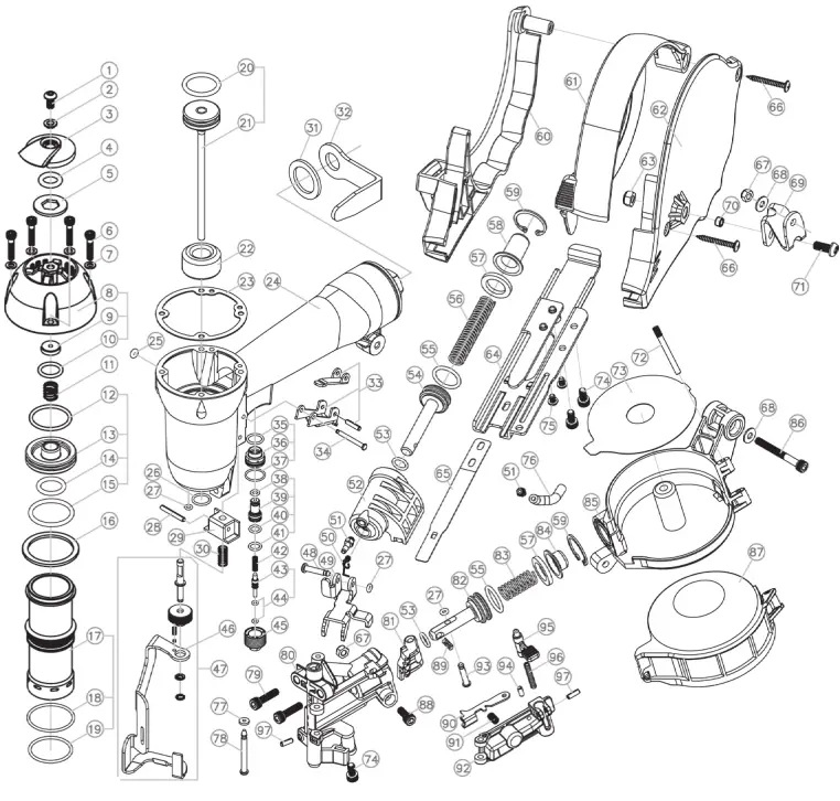
STINGER CN100 PARTS LIST
| Ref No. | Item No. | Description |
| 1 | 136665 | CAP SCREW M5-0 |
| 2 | 135851 | WASHER |
| 3 | 135951 | EXHAUST DEFLECTOR |
| 4 | 137973 | O-RING |
| 5 | 135854 | WASHER |
| 6 | 137953 | CAP SCREW |
| 7 | 135856 | FLAT WASHER |
| 8 | 137965 | CAP |
| 9 | 136627 | EXHAUST SEAL |
| 10 | 136628 | O-RING |
| 11 | 136630 | POPPET SPRING |
| 12 | 136643 | POPPET -O-RING |
| 13 | 136642 | POPPET SPRING |
| 14 | 137976 | PISTON STOP O-RING |
| 15 | 137979 | CYLINDER SEAL O-RING |
| 16 | 553031 | CYLINDER SPACER |
| 17 | 137908 | CYLINDER |
| 18 | 137969 | CYLINDER O-RING |
| 19 | 553029 | CYLINDER O-RING |
| 20 | 136615 | PISTON O-RING |
| 21 | 137900 | PISTON & DRIVER Assembly |
| 22 | 553001 | BUMPER |
| 23 | 137966 | GASKET |
| 24 | 137904 | BODY |
| 25 | 136621 | O-RING VALVE |
| 26 | 137972 | O-RING |
| 27 | 137986 | O-RING |
| 28 | 136653 | SPRING PIN |
| 29 | 135897 | SAFETY GUIDE |
| 30 | 136658 | SAFETY YOKE SPRING |
| 31 | 135947 | WASHER |
| 32 | 135948 | BELT CLIP |
| 33 | 135946 | TRIGGER ASSEMBLY |
| 34 | 136623 | TRIGGER PIN |
| 35 | 135878 | O-RING |
| 36 | 135879 | TRIGGER VALVE (A) |
| 37 | 135880 | O-RING |
| 38 | 135881 | O-RING |
| 39 | 135882 | TRIGGER VALVE (B) |
| 40 | 135883 | O-RING |
| 41 | 135884 | O-RING |
| 42 | 135885 | SPRING PIN |
| 43 | 135887 | PLUNGER |
| 44 | 135886 | O-RING (2) |
| 45 | 135888 | TRIGGER VALVE HOUSING |
| 46 | 137964 | SAFETY |
| 47 | 137902 | SAFETY ASSEMBLY |
| 48 | 136647 | PIN |
| 49 | 137912 | CAP FEEDER |
| 50 | 135909 | SPRING PIN |
| 51 | 136645 | 10-32 X 1/8″ BARB |
| 52 | 135910 | FEED CYLINDER |
| 53 | 135911 | O-RING (2) |
| 54 | 135912 | FEED PISTON (caps) |
| 55 | 135913 | O-RING (2) |
| 56 | 135914 | LONG FEED PISTON SPRING (caps) |
| 57 | 135915 | PISTON STOP |
| 58 | 135916 | FEED PISTON COVER |
| 59 | 135917 | RETAINING RING |
| 60 | 135919 | CAP MAGAZINE RIGHT |
| 61 | 137920 | CAP MAGAZINE COVER |
| 62 | 137921 | CAP MAGAZINE LEFT |
| 63 | 137957 | LOCK NUT |
| 64 | 137925 | FEED CHUTE – GCS8116 |
| 65 | 135918 | HOLD DOWN SPRING |
| 66 | 135922 | SCREW |
| 67 | 137955 | LOCK NUT |
| 68 | 136611 | WASHER |
| 69 | 137926 | BRACKET |
| 70 | 135923 | SPACER |
| 71 | 135924 | SCREW |
| 72 | 135907 | PIN |
| 73 | 137992 | NAIL SUPPORT |
| 74 | 137953 | SCREW (3) |
| 75 | 135926 | SCREW (2) |
| 76 | 137996 | TUBING |
| 77 | 137987 | RUBBER WASHER |
| 78 | 137913 | PIN |
| 79 | 137946 | SOCKET HEAD CAP SCREW M5-0 |
| 80 | 137917 | NOSE |
| 81 | 137906 | FEED PAWL |
| 82 | 137989 | FEED PISTON |
| 83 | 137936 | SPRING |
| 84 | 137922 | FEED PISTON COVER |
| 85 | 137923 | NAIL MAGAZINE |
| 86 | 137954 | SCREW |
| 87 | 137924 | NAIL MAGAZINE COVER |
| 88 | 137947 | SCREW |
| 89 | 137937 | SPRING PIN |
| 90 | 137944 | CHECK PAWL |
| 91 | 137938 | SPRING PIN |
| 92 | 137993 | DOOR LATCH |
| 93 | 137914 | PIN |
| 94 | 137915 | PIN |
| 95 | 137945 | DOOR LATCH |
| 96 | 137939 | SPRING PIN |
| 97 | 137916 | PIN |
* Parts included in AS‐97377 O‐Ring and Seal Kit
MAINTENANCE & STORAGE
MAINTENANCE
- Disconnect the air hose from the tool when performing inspections, maintenance or repairs.
- Use air line lubricators. f lubricators are not available, or if hose lengths exceed 10 feet, add 2 drops of non‐detergent 20‐weight oil daily into the air inlet of the tool.
- Whenever repairs or replacement of parts inside the body occur, check the piston “O” ring for adequate grease lubrication.
- Never use any parts other than genuine STINGER replacement parts.
- Periodically clean the nose of the tool with a mild solvent.
STORAGE
- Disconnect the air hose when storing the tool.
- Never store the tool in cold weather environments for any duration of time as any frost or ice formation in the tool will cause tool failures.
- For prolonged storage, add 2 drops of oil to the air inlet of the tool prior to discontinuing use. Also clean the exterior of the tool with a mild solvent.
WARRANTY
WARRANTY ITEMS
- Warranty for cap assemblies, castings and housing castings is one year.
- Warranty for bumpers, “O” rings, driver blades and piston rings is not applicable as they are normal wearing parts whose life is dependant on application.
- Warranty for all other parts is 90 days.
WARRANTY CONDITIONS
- The beginning date on which the warranty is in force is the date of purchase.
- The warranty is not transferable.
- The warranty is voided by any of the following:
a. Abuse, misuse, or damage to the tool
b. Use of parts other than genuine STINGER parts
c. Use of fasteners not designated for use in the tool
d. Modifications to the tool that alter the original function or intent of use of the tool by anyone other than National Nail Corp. - National Nail Corp. retains the right to replace or repair any warranty items it deems necessary.
TROUBLESHOOTING
Disconnect the air hose from the tool when performing inspec&ons, maintenance or repairs.
| PROBLEM: | CORRECTION: |
| 1. Tool operates, but no fasteners are driven. | • Check magazine for proper fasteners. Fasteners should slide freely in and out of the magazine. |
| 2. Cap leaks air. | • Tighten cap screws. |
| 3. Fasteners jam in nose of tool. | • Un‐plug tool from air supply. • Open nail gate. • Remove fasteners from magazine. • Remove jammed fastener and close nail gate. • Load tool. |
| 4. Skipping fasteners | • Replace bumper if worn. • Use only recommended fastener size. • Check air supply as it may be too low or on too high. |
| 5. Fasteners will not drive completely into work piece | • Increase air pressure (do not exceed 105 PSI). • Check depth of drive segng. |
Please contact Inside Sales for technical support if you have any other problems: 800‐746‐5659
Contact Inside Sales at 800‐746‐5659 to place an order for replacement parts.
![]() Visit our website at
Visit our website at
www.stingerworld.com
to learn more about our products and services.
2964 Clydon SW, Grand Rapids MI 49519, USA
Phone: 800‐968‐6245 Fax: 616‐531‐5970
www.nationalnail.com


