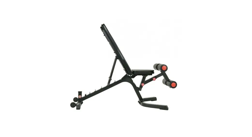
![]() SF-BH6920 Fully Adjustable Utility Weight Bench
SF-BH6920 Fully Adjustable Utility Weight Bench
User Manual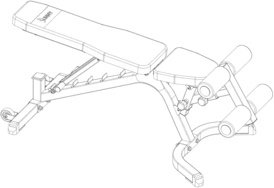
IMPORTANT! Please retain the owner’s manual for maintenance and adjustment instructions.
Your satisfaction is very important to us, PLEASE DO NOT RETURN UNTIL YOU HAVE CONTACTED US: [email protected] or 1- 877 – 90SUNNY (877-907-8669).
IMPORTANT SAFETY INFORMATION
We thank you for choosing our product. To ensure your safety and health, please use this equipment correctly. It is important to read this entire manual before assembling and using the equipment. Safe and effective use can only be achieved if the equipment is assembled, maintained, and used properly. It is your responsibility to ensure that all users of the equipment are informed of all warnings and precautions.
- Before starting any exercise program, you should consult your physician to determine if you have any medical or physical conditions that could put your health and safety at risk or prevent you from using the equipment properly. Your physician’s advice is essential if you are taking medication that affects your heart rate, blood pressure, or cholesterol level.
- Be aware of your body’s signals. Incorrect or excessive exercise can damage your health. Stop exercising if you experience any of the following symptoms: pain, tightness in your chest, irregular heartbeat, shortness of breath, lightheadedness, dizziness, or feelings of nausea. If you do experience any of these conditions, you should consult your physician before continuing with your exercise program.
- Keep children and pets away from the equipment. The equipment is designed for adult use only.
- Use the equipment on a solid, flat-level surface with a protective cover for your floor or carpet. To ensure safety, the equipment should have at least 4 feet (120 CM) of free space all around it.
- Ensure that all nuts and bolts are securely tightened before using the equipment. The safety of the equipment can only be maintained if it is regularly examined for damage and/or wear and tear.
- Always use the equipment as indicated. If you find any defective components while assembling or checking the equipment, or if you hear any unusual noises coming from the equipment during exercise, discontinue use of the equipment immediately, and do not use it until the problem has been rectified.
- Wear suitable clothing while using the equipment. Avoid wearing loose clothing that may become entangled in the equipment.
- Do not place fingers or objects into the moving parts of the equipment.
- The maximum weight capacity of this unit is 1000 LBS (455KG).
- The equipment is not suitable for therapeutic use.
- To avoid bodily injury and/or damage to the product or property, proper lifting and moving are required.
- Your product is intended for use in cool and dry conditions. You should avoid storage in extreme cold, hot or damp areas as this may lead to corrosion and other related problems.
- This equipment is designed for indoor and home use only; it is not intended for commercial use.
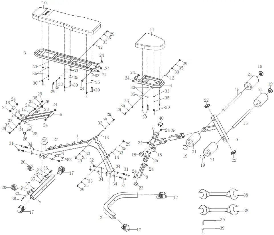
EXPLODED DIAGRAM
HARDWARE PACKAGE
| #31 M12*75 4PCS |  | #34 ¢13*¢24*2.5 8PCS | |
| #32 M12 4PCS |  | #24 ¢25*¢20.8*¢12.5*10*3 10PCS | |
| #29 M8*20 6PCS | #33 ¢8.4*¢16*1.5 16PCS | ||
| #30 M8*45 10PCS |  | #35 ¢8.1*12.3*2.1 16PCS | |
| #13 ¢12.5*176 1PC | #19 ¢60 4PCS | ||
| #12 ¢12.5*128 2PCS | #18 ¢10*10*M16*25 2PCS | ||
| #38 S16-S18 2PCS |  | #39 5mm 2PCS |
PARTS LIST
| No. | Description | Spec. | Qty. | No. | Description | Spec. | Qty. | |
| 1 | Main Frame | 1 | 21 | Sponge | ¢ 100*200 | 4 | ||
| 2 | Front Stabilizer | 1 | 22 | Square End Cap | 50*5012.0 | 2 | ||
| 3 | Backrest Frame | 1 | 23 | Square End Cap | 38*38*t2.0 | 1 | ||
| 4 | Seat Frame | 1 | 24 | Alloy Bushing | ¢ 25*¢ 20.8* o 12.5*10*3 | 18 | ||
| 5 | Backrest Adjusting Frame | 1 | 25 | Bushing | 50*5012.0, for tube 38*38 | 2 | ||
| 6 | Seat Adjusting Frame | 1 | 26 | Round End Cap | ¢ 31*¢ 25*1.5 | 2 | ||
| 7 | Rear Stabilizer | 1 | 27 | Rubber Mat | 50*50*t5.0 | 1 | ||
| 8 | Adjusting Tube | 1 | 28 | Foam Grip | ¢ 24* ¢ 32*58 | 2 | ||
| 9 | Foot Post | 1 | 29 | Bolt | M8*20 | 10 | ||
| 10 | Backrest Cushion | 1 | 30 | Bolt | M8*45 | 10 | ||
| 11 | Seat Cushion | 1 | 31 | Hex Bolt | M12*75 | 4 | ||
| 12 | Rotation Rod 1 | ¢ 12.5128 | 3 | 32 | Hex Nut | M12 | 4 | |
| 13 | Rotation Rod 2 | ¢ 12.5176 | 1 | 33 | Washer | ¢ 8.4*0 16*1.5 | 24 | |
| 14 | Rotation Rod 3 | ¢ 12.5*60 | 1 | 34 | Washer | ¢ 13* a. 24*2.5 | 8 | |
| 15 | Foot Tube | ¢ 25*t2.0*450 | 2 | 35 | Spring Washer | ¢ 8.1*12.3*2.1 | 20 | |
| 16 | Rotation Tube 1 | 1 | 36 | Bolt | M8*55 | 2 | ||
| 17 | End Cap | 4 | 37 | Hex Nut | M8 | 2 | ||
| 18 | Knob | ¢ 1010*M16*25 | 2 | 38 | Open End Wrench | S16-S18 | 2 | |
| 19 | End Cap | ¢ 60 | 4 | 39 | Allen Wrench | 5mm | 2 | |
| 20 | Transportation Wheel | ¢ 8* a 77.5*33.5 | 2 | 40 | Square End Cap | 45*4511.5 | 1 |
Ordering Replacement Parts (the U.S. and Canadian Customers Only)
Please provide the following information in order for us to accurately identify the part(s) needed:![]() The model number (found on the cover of the manual)
The model number (found on the cover of the manual)![]() The product name (found on the cover of the manual)
The product name (found on the cover of the manual)![]() The part number found on the “EXPLODED DIAGRAM” and “PARTS LIST” (found near the front of the manual)
The part number found on the “EXPLODED DIAGRAM” and “PARTS LIST” (found near the front of the manual)
Please contact us at [email protected] or 1- 877- 90SUNNY (877-907-8669).
ASSEMBLY INSTRUCTIONS
We value your experience using Sunny Health and Fitness products. For assistance with parts or troubleshooting, please contact us at [email protected] or 1-877-90SUNNY (877-907-8669).
STEP 1:
Attach Front Stabilizer (No. 2) and Rear Stabilizer (No. 7) to Main Frame (No. 1) using 4 Hex Bolts (No. 31), 4 Hex Nuts (No. 32), and 8 Washers (No. 34). Tighten and secure with 2 Open End Wrenches (No. 38).
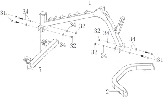
| #31 M12*75 4PCS | | #34 ¢13*¢24*2.5 8PCS | |
| #32 M12 4PCS | #38 S16-S18 2PCS |
STEP 2:
Insert 2 Alloy Bushings (No. 24) into the Backrest Adjusting Frame (No. 5). Then attach Backrest Frame (No. 3) to Backrest Adjusting Frame (No. 5) using 2 Bolts (No. 29), 2 Washers (No. 33), 2 Spring Washers (No. 35), and Rotation Rod 1 (No. 12). Tighten and secure with 2 Allen Wrenches (No. 39).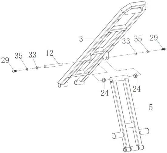
| #29 M8*20 2PCS | | #24 ¢25*¢20.8*¢12.5*10*3 2PCS | |
| #33 ¢8.4*¢16*1.5 2PCS | #12 ¢12.5*128 1PC | |
| #35 ¢8.1*12.3*2.1 2PCS | | #39 5mm 2PCS |
STEP 3:
Insert 4 Alloy Bushings (No. 24) into the Backrest Frame (No. 3). Attach Backrest Frame (No. 3) onto Main Frame (No. 1), then align the holes on Backrest Frame (No. 3) with the holes on Main Frame (No. 1) and insert Rotation Rod 2 (No. 13) into the holes on side A of Main Frame (No. 1).
NOTE: Do not insert the Rotation Rod 2 (No. 13) exceed side A at this step.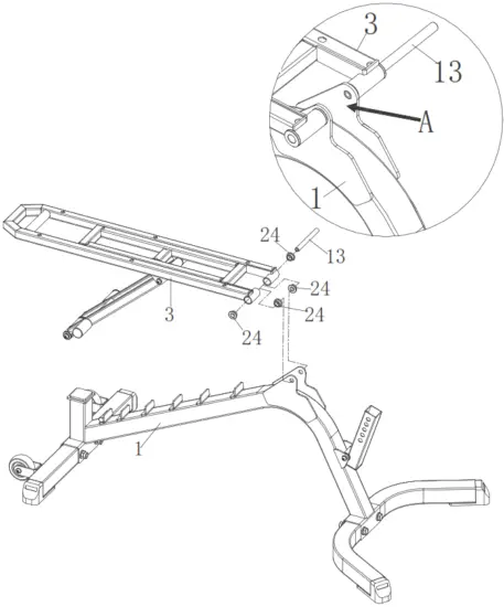
| #24 ¢25*¢20.8*¢12.5*10*3 4PCS | #13 ¢12.5*176 1PC |
STEP 4:
Insert 2 Alloy Bushings (No. 24) into Seat Frame (No. 4). Attach Seat Frame (No. 4) onto Main Frame (No. 1), then align the holes on Seat Frame (No. 4) with the holes on ain
The frame (No. 1) and insert Rotation Rod 2 (No. 13) into the holes on Seat Frame (No. 4) and Main Frame (No. 1) using 2 Bolts (No. 29), 2 Washers (No. 33), and 2 Spring Washers (No. 35). Tighten and secure with 2 Allen Wrenches (No. 39).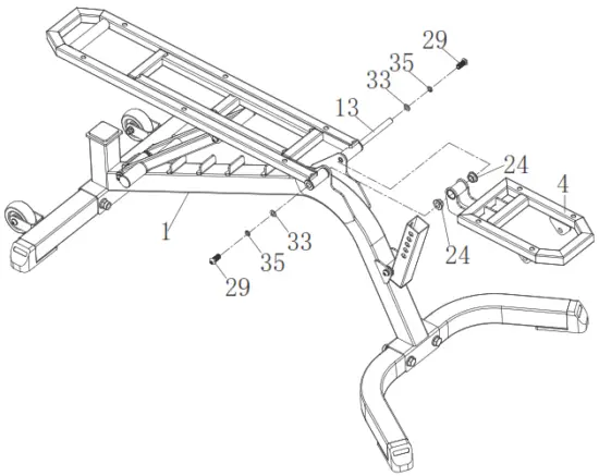
| #29 M8*20 2PCS | | #24 ¢25*¢20.8*¢12.5*10*3 2PCS | |
| #33 ¢8.4*¢16*1.5 2PCS | | #39 5mm 2PCS |
| #35 ¢8.1*12.3*2.1 2PCS |
STEP 5:
Insert Foot Post (No. 9) into Seat Adjusting Frame (No. 6), then insert Seat Adjusting Frame (No. 6) into Adjusting Tube (No. 8).
Insert 2 Alloy Bushings (No. 24) into Seat Adjusting Frame (No. 6). Attach Seat Frame (No. 4) onto Seat Adjusting Frame (No. 6), then align the holes on Seat Frame (No. 4) with the holes on the Seat Adjusting Frame (No. 6) and insert 2 Bolts (No. 29), 2 Washers (No. 33), 2 Spring Washers (No. 35) and Rotation Rod 1 (No. 12). Tighten and secure with 2 Allen Wrenches (No. 39).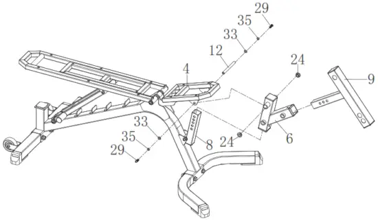
| #29 M8*20 2PCS | | #24 ¢25*¢20.8*¢12.5*10*3 2PCS | |
| #33 ¢8.4*¢16*1.5 2PCS | #12 ¢12.5*128 1PC | |
| #35 ¢8.1*12.3*2.1 2PCS | | #39 5mm 2PCS |
STEP 6:
Attach Backrest Cushion (No. 10) to Backrest Frame (No. 3) using 6 Bolts (No. 30), 6 Washers (No. 33), and 6 Spring Washers (No. 35). Tighten and secure with Allen Wrench (No. 39).
Attach Seat Cushion (No. 11) to Seat Frame (No. 4) using 4 Bolts (No. 30), 4 Washers (No. 33), and 4 Spring Washers (No. 35). Tighten and secure with Allen Wrench (No. 39).
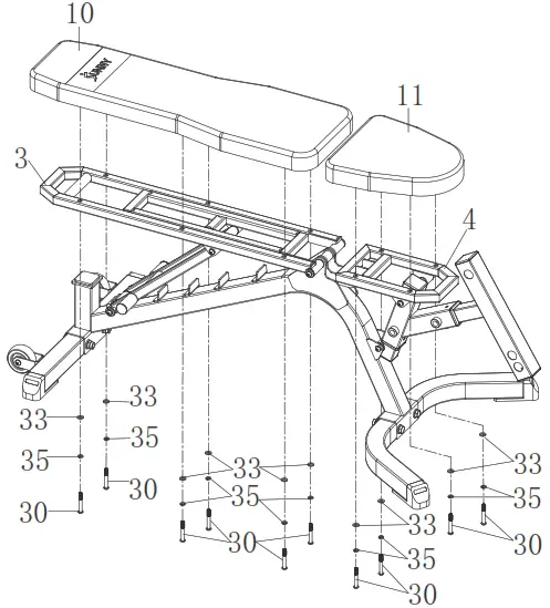
| #30 M8*45 10PCS | | #35 ¢8.1*12.3*2.1 10PCS | |
| #33 ¢8.4*¢16*1.5 10PCS | | #39 5mm 1PC |
STEP 7:
Insert 2 Foot Tubes (No. 15) into Foot Post (No. 9). Then attach 4 Sponges (No. 21) and 4 End Caps (No. 19) onto 2 Foot Tubes (No. 15). Insert 2 Knobs (No. 18) into Seat Adjusting Frame (No. 6).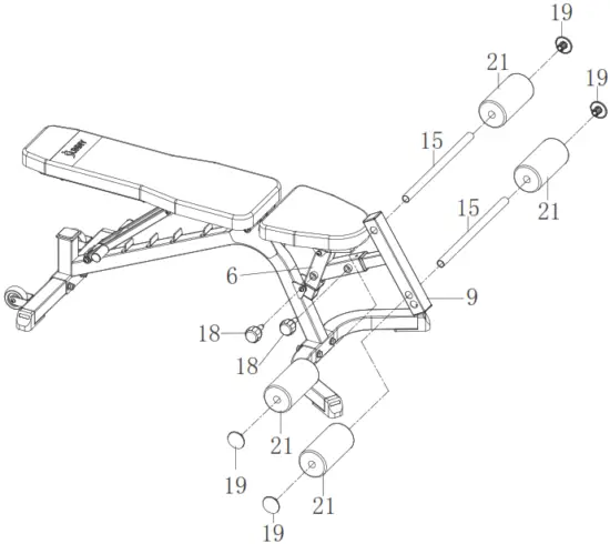
| #18 ¢10*10*M16*25 2PCS | |
| #19 ¢60 4PCS |
The assembly is complete!
ADJUSTMENTS & USAGE GUIDE
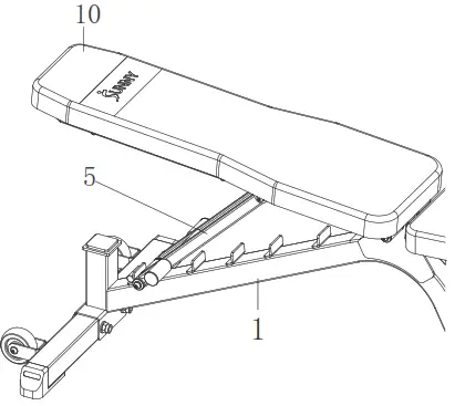 | ADJUSTING THE BACKREST |
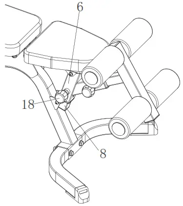 | ADJUSTING THE SEAT There are 4 levels for adjusting the seat. To adjust the seat, loosen and pull out the Knob (No. 18), and adjust the Adjusting Tube (No. 8) to the desired position. Once adjusted, re-insert and tighten the Knob (No. 18) to secure the Adjusting Tube (No. 8) in place. |
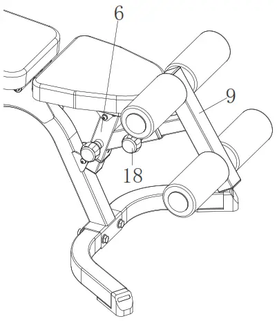 | ADJUSTING THE FOOT POST There are 3 levels for adjusting the Foot Post (No. 9). To adjust the Foot Post (No. 9), loosen and pull out the Knob (No. 18), and adjust the Foot Post (No. 9) to the desired position. Once adjusted, re-insert and tighten the Knob (No. 18) to secure the Foot Post (No. 9) in place. |
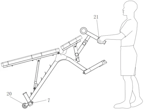 | TRANSPORTING THE BENCH |
MAINTENANCE INSTRUCTIONS
DAILY MAINTENANCE
Inspect and tighten all parts regularly. (Nuts, Bolts, Rubber Pads, Steel Brackets, etc.)
Replace any worn or torn parts immediately.
Check and ensure the bench is leveled at all times.
Check and tighten all adjustment pins/knobs regularly.
WEEKLY MAINTENANCE
Use a damp cloth on plastic parts only, use a dry cloth on metal frames.
Inspect the metal frame structure of the equipment.
CONNECT WITH US
FOR FITNESS ARTICLES, VIDEOS & WORKOUTS
 https://sunnyhealthfitness.com/pages/sign-up
![]() @SUNNYHEALTHANDFITNESS
@SUNNYHEALTHANDFITNESS @SUNNYHEALTHFITNESS
![]() @SUNNYHEALTHFIT
@SUNNYHEALTHFIT /SUNNYHEALTHFITNESS
![]() /SUNNYHEALTHANDFITNESS
/SUNNYHEALTHANDFITNESS
WWW.SUNNYHEALTHFITNESS.COM
Version: 2.1


