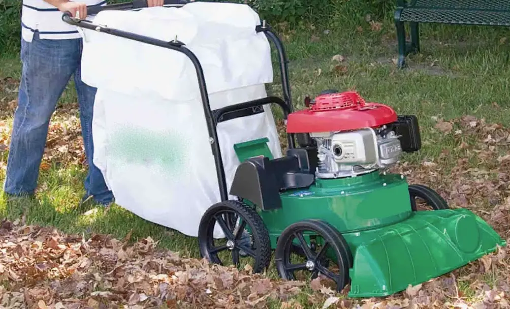
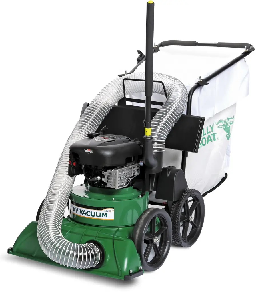
BILLY GOAT KV Self Propelled Lawn Litter Vacuum
SPECIFICATIONS
| Engine HP | 4.95 (3.69 kW) | 6.5 (4.85kW) | 6.5 (4.85kW) | 4.95 (3.69 kW) | 6.5 (4.85kW) | 6.5 (4.85kW) |
| Engine type | B&S Professional Series | HONDA | HONDA | B&S Professional Series | HONDA | HONDA |
| Engine model | 121R | GSV190LN1L | GSV190LN1L | 121R | GSV190LN1L | GSV190LN1L |
| Engine fuel capacity | 1.2 qt. (1.14 L) | 1.6 qt. (1.5 L) | 1.6 qt. (1.5 L) | 1.2 qt. (1.14 L) | 1.6 qt. (1.5 L) | 1.6 qt. (1.5 L) |
| Engine oil capacity | 0.56 qt. (0.53 L) | 0.58 qt. (0.54 L) | 0.58 qt. (0.54 L) | 0.56 qt. (0.53 L) | 0.58 qt. (0.54 L) | 0.58 qt. (0.54 L) |
| Total unit weight | 133lb (60.3 kg) | 135lb (61.2 kg) | 141lb (64 kg) | 133lb (60.3 kg) | 135lb (61.2 kg) | 141lb (64 kg) |
| Overall length | 59” (1.5m) | 59” (1.5m) | 59” (1.5m) | 59” (1.5m) | 59” (1.5m) | 59” (1.5m) |
| Overall width | 25.5” (.6m) | 25.5” (.6m) | 25.5” (.6m) | 25.5” (.6m) | 25.5” (.6m) | 25.5” (.6m) |
| Overall height | 42.75” (1.1m) | 42.75” (1.1m) | 42.75” (1.1m) | 42.75” (1.1m) | 42.75” (1.1m) | 42.75” (1.1m) |
| Max. operating slope | 200 | 200 | 200 | 200 | 200 | 200 |
SAFETY
WARNING
This product can expose you to chemicals including gasoline engine exhaust, which is known to the State of California to cause cancer, and carbon monoxide, which is known to the State of California to cause birth defects or other reproductive harm. For more information go to www.P65Warnings.ca.gov.
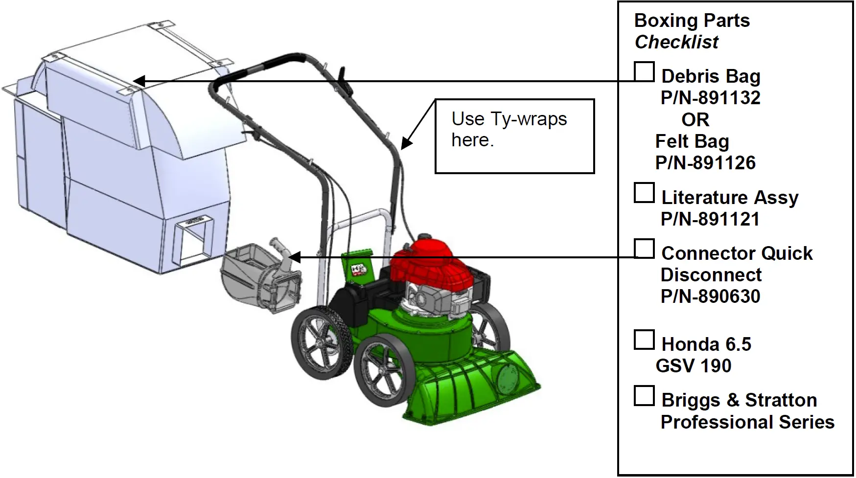
PACKING CHECKLIST
Your Billy Goat KV Vacuum is shipped from the factory in one carton, completely assembled except for the upper handle, debris bag, and bag quick disconnect.
READ all safety instructions before assembling unit.
TAKE CAUTION when removing the unit from the box, the Handle Assembly is attached by cables and folded over.
PUT OIL IN ENGINE BEFORE STARTING
PARTS BAG & LITERATURE ASSY
Warranty card P/N- 400972, Owner’s Manual P/N-891204, General Safety and Warnings Manual P/N-100294, Declaration of Conformity P/N-891057, Ty-wraps 900407 qty 2.
ASSEMBLY INSTRUCTIONS
NOTE: Items in can be referenced in the Parts Illustration and Parts List found at the back of the manual.
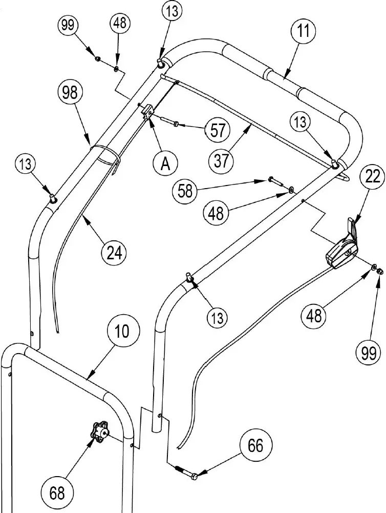
- ASSEMBLE the upper handle (Item 11) to the lower handle (Item 10). Line up the holes on the upper and lower handles. Insert bolt (Item 66) with threads facing inside. Fasten the handles together with the black knob (Item 68). Thread the knob onto the bolt, and hand-tighten by rotating the knob clockwise. Repeat this step on the other side of the handle to secure the upper handle to the lower handle.
- ATTACH the throttle lever (Item 22) to outside the handle tubing. Insert bolt (Item 58) with washer (Item 48) from the inside, with threads facing out. Secure the throttle lever with second washer (Item 48) and acorn nut (Item 99). Tighten with a 7/16” socket and wrench. Once attached, use a zip-tie to secure the cable to the handle. Trim excess zip-tie with snips.
- ATTACH the clutch cable (Item 24). Route the clutch cable on the handle, up to the bail. On the end of the clutch cable is a fitting. Install the fitting into the hole on the bail (Item 37). Use 1.5” bolt (Item 57), with threads facing out, to fasten the plastic cable connection (A) on the inside of the handle. Secure the plastic cable connection with washer
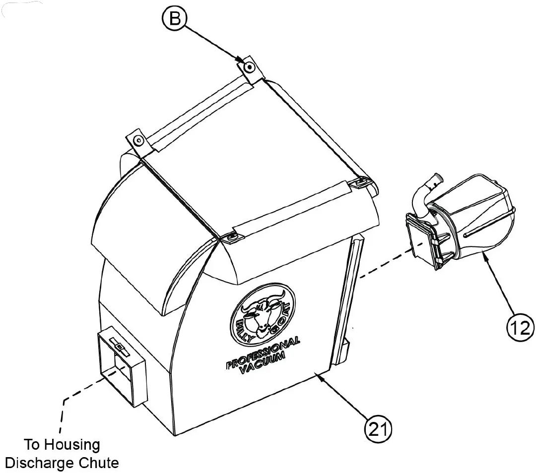
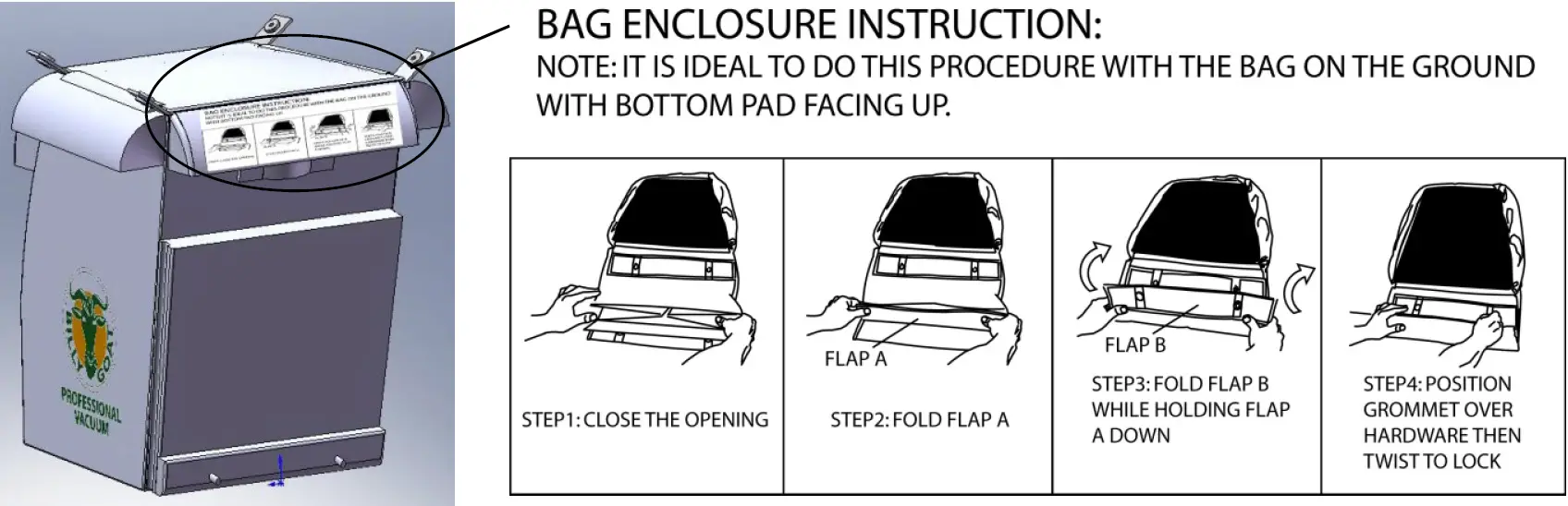
(Item 48) and acorn nut (Item 99). Tighten with 7/16” socket and wrench. Secure the clutch cable to the handle with a zip-tie (Item 98). Trim excess zip-tie with snips. - UNFOLD the debris bag (Item 21). Locate the quick disconnect scoop (Item 12). Insert the quick disconnect scoop into the bag through the large opening. Maneuver the quick disconnect scoop through the bag and out the small opening. Tighten the ratchet strap over the quick disconnect scoop to secure. Close the large opening of the debris bag.
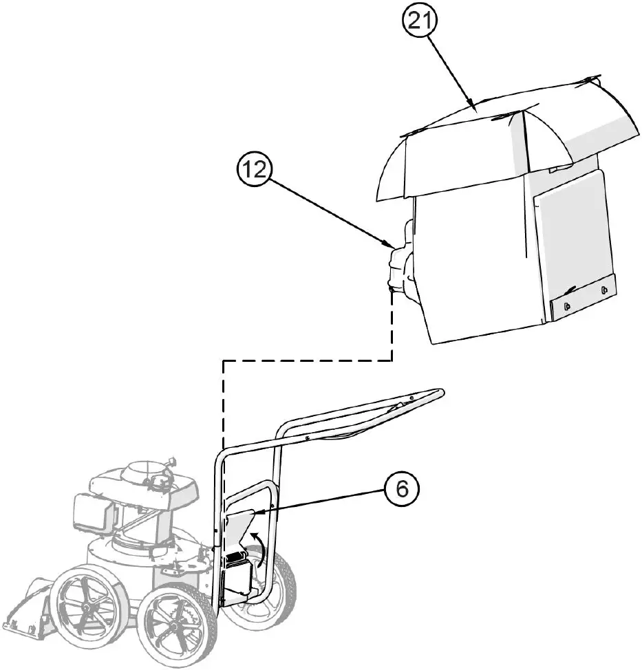
- INSTALL the debris bag onto the housing discharge chute. Open the discharge flap (Item 6) at the back of the housing. Slide the quick disconnect scoop downward onto the housing discharge chute.
- ATTACH the debris bag to the upper handle. Note the bag straps in each of the four corners of the bag. Each strap has an eyelet (B). Use the eyelets to hang the bag onto the upper handle posts (Item 13).
- CONNECT spark plug wire from the engine to the unit.
- FILL the engine with oil and gasoline before starting.


OPERATION
VACUUMING OPERATION
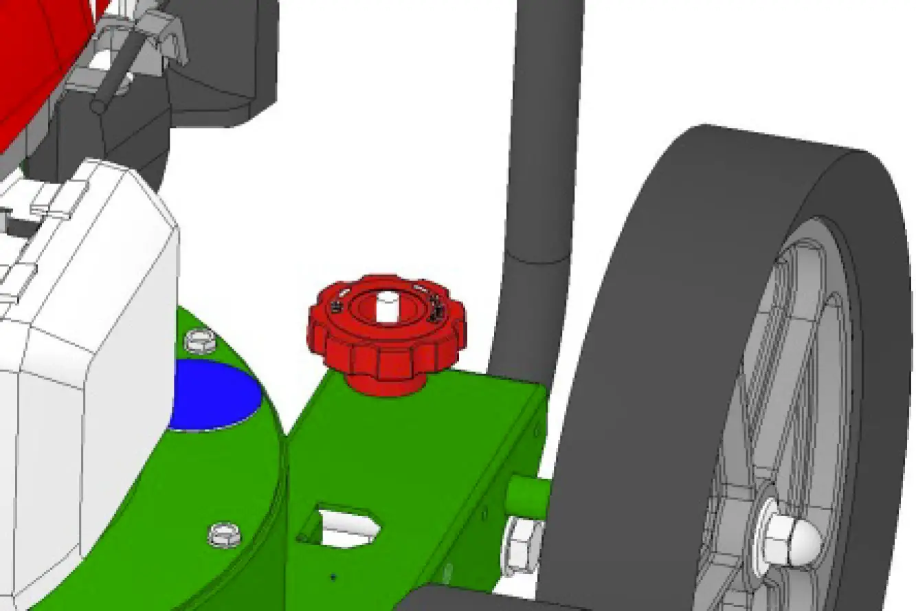
VACUUM NOZZLE HEIGHT ADJUSTMENT: Nozzle height is raised and lowered by rotating the red knob near the left rear wheel. Nozzle height should be adjusted based on the task being performed.
FOR MAXIMUM PICKUP: Adjust nozzle close to debris, but without blocking airflow into the nozzle.
NOTE: Never bury nozzle into debris.
CLEARING A CLOGGED NOZZLE & EXHAUST: Turn the engine off and wait for impeller to stop completely and disconnect the spark plug wire. Wearing durable gloves, remove clog. Danger, the clog may contain sharp materials. Reconnect spark plug wire.
DEBRIS BAG
Optional debris bags are available for changing conditions.
Debris bags are normal replaceable wear items.
NOTE: Frequently empty debris to prevent bag overloading with more weight than you can lift.
An optional felt bag is available for use where debris will be vacuumed in dusty conditions. DO NOT place bag on or near hot surface, such as engine. Be sure engine has come to a complete stop before removing or emptying bag.
This vacuum is designed for picking up trash, organic material and other similar debris.
However, many vacuums are used where dust is mixed with trash. Your unit can intermittently vacuum in dusty areas. Dust is the greatest cause of lost vacuum performance. Following these rules will help maintain your machine’s ability to vacuum in dusty conditions:
- Run machine at idle to quarter throttle.
- The debris bag must be cleaned more frequently. A vacuum with a clean, pillow soft bag will have good pickup performance. One with a dirty, tight bag will have poor pickup performance. If dirty, empty debris and vigorously shake bag free of dust.
- Pressure-wash debris bag if normal cleaning does not fully clean bag. Bag should be thoroughly dry before use.
NOTE: Having one or more spare debris bags is a good way to reduce down time while dirty bags are being cleaned.
DO NOT leave debris in bag while in storage.
COMPOST
Vacuumed leaves, grass and other organic material from your own yard can be emptied into a pile or composter to provide enriched soil for later use as fertilizer in gardens and flower beds.
NOTE: Allow green chips to dry before spreading around living plants.
MULCH
Wood chips made from branches in your own yard make excellent mulch. A thick blanket of wood chips around plants and flowers to keeps weeds out and moisture in.
CHIPPER OPERATION (TKV only)
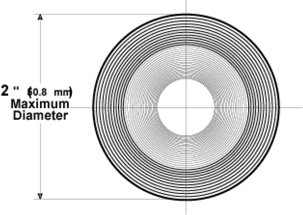
Your TKV chipper is designed to process tree branches and limbs up to 2″ (50.8mm) diameter.
Several small branches can be grouped together and fed together into the chipper.
When feeding forked branches, squeeze forks together and feed into chipper entrance.
DO NOT overload. If forks are too large, use a pair of loppers to trim forks down to size.
CLEARING A CLOGGED CHIPPER (TKV only)
Under normal circumstances, allow time for machine to clear all wood from chipper hopper before stopping engine. Otherwise, remaining pieces of wood will jam inside of c hipper when engine stops.
Disconnect Spark Plug Wire
Remove debris bag quick disconnect from debris outlet on machine. Wearing durable gloves, access impeller through debris outlet on fan housing and rotate impeller counter clock wise to dislodge and remove jam and remove debris from hopper with tongs or equivalent. Reconnect debris bag quick disconnect to machine and then reconnect the spark plug wire.
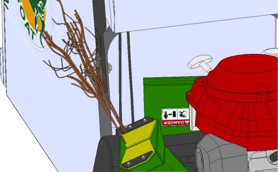
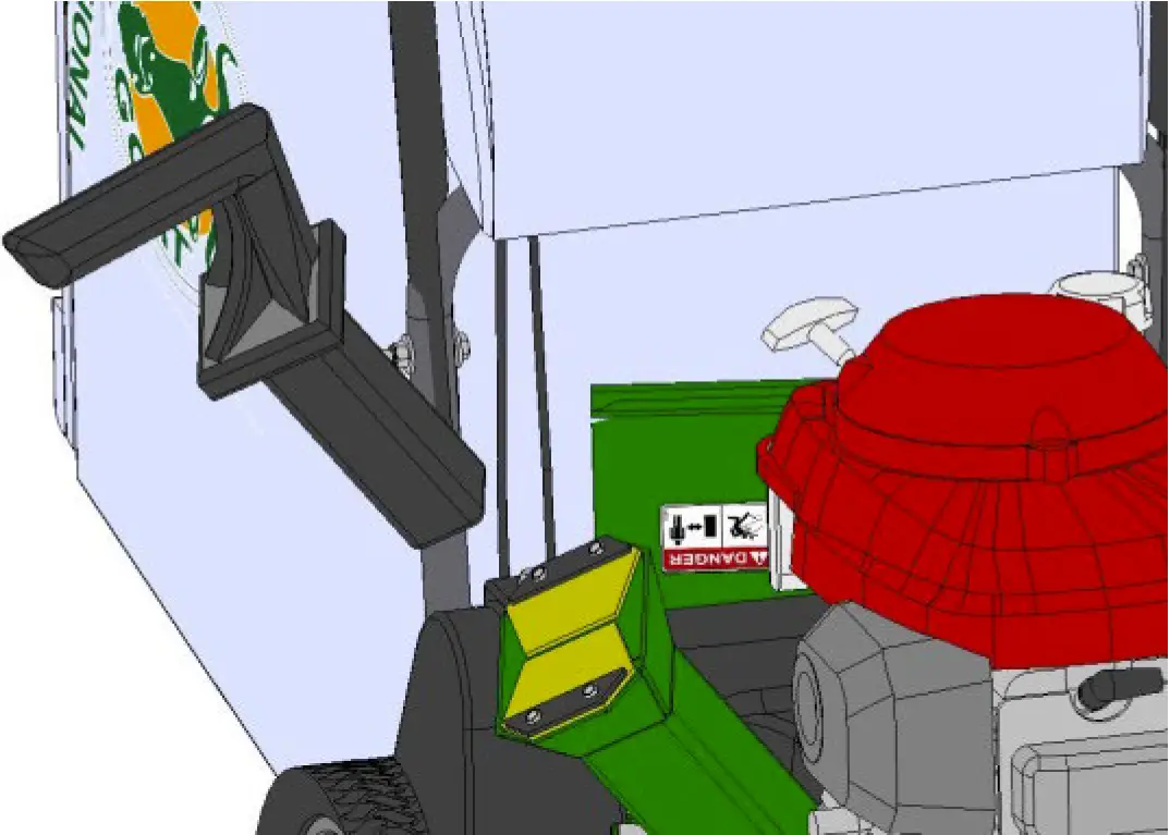
TAMPER (TKV only)
Before turning machine off, use the tamper to slowly push remaining pieces of wood through the chipper. This can prevent any remaining wood from jamming in the chipper when machine is turned off.
Do not leave tamper on the ground, store tamper in the chipper hopper.
MAINTENANCE
PERIODIC MAINTENANCE
Periodic maintenance should be performed at the following intervals:
| Maintenance Operation | Every Use (Daily) | Every 5 Hrs (Daily) | Every 25 Hours |
| Inspect for loose, worn or damaged parts | ✓ | ||
| Clean debris bag | ✓ | ||
| Check bag strap tightness | ✓ | ||
| Engine (See Engine Manual) | |||
| Check for excessive vibration | ✓ |
IMPELLER REMOVAL
- Wait for engine to cool and disconnect spark plug.
- Drain fuel and oil from the engine.
- Remove bag, quick release and upper handle. Do not kink, stretch, or break control cables, control housings, or end fittings while removing handles.
- Remove the transmission cover, idler pulley, transmission and the belt from the transmission.
- Remove the transmission plate and the housing top plate by removing bolts around outside of housing.
- Leaving engine fastened to top plate; turn it upside down so the impeller is on top.
- Remove impeller bolt and lock washer.
- Lift impeller upward. If impeller slides freely, proceed to step 10.
- If the impeller does not loosen, obtain a 3/4-16×3” (Billy Goat P/N 440192) or longer bolt. Thread bolt by hand into nut until bolt rests against the shaft. Tighten the bolt slowly, which will pull the impeller away from the shaft, remove impeller from shaft. Using a penetrating oil can help loosen a stuck impeller.
- Using a new impeller bolt, lock washer, and washer, reinstall new impeller in reverse order.
- Tighten impeller bolt. Torque impeller bolt to 33-38 ft. lbs. (44-51 N.m).
- Reinstall engine onto housing in reverse order of removal. Make sure the belt is inside the two fingers on the belt plate and that the belt is on the transmission pulley before securing the transmission.
- Gas and oil engine.
- Reconnect spark plug wire.
DRIVE CHAIN REPLACEMENT AND ALIGNMENT
- Wait for engine to cool and disconnect spark plug.
- To replace a chain, first prop up the rear of the machine with small blocks to get the rear wheels off of the ground.
- Remove the transmission cover, and the belt from the transmission.
- Remove the bolts on both sides of the transmission holding the flange bearings; this should give enough slack to slip the chain off.
- Replace the old chain with a new one.
- Once the chain is on, put the bolts back into the flange bearings and tighten.
- Finally, make sure the wheels rotate freely. If not, loosen the bearings and shift them to get the chain running straight up and down.
- Reassemble the transmission components removed in steps 1-3 in reverse order.
BELT TENSION ADJUSTMENT
DO NOT ADJUST WHILE THE MACHINE IS RUNNING!
- Wait for engine to cool and disconnect spark plug.
- Remove the transmission cover.
- Using two 1/2″ wrenches, loosen the two nuts on the cable that connects to the idler arm.
- The setting of the tension on the belt is controlled by the distance on the threads of the cable. To loosen tension, move the position towards the end of the threads. Move in the opposite direction to tighten.
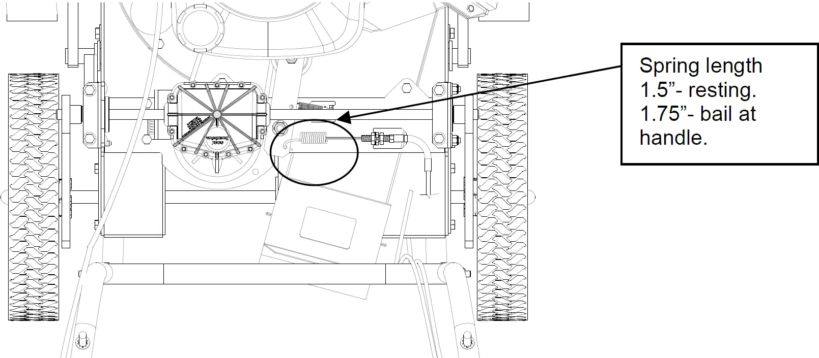
- Check the travel of the idler arm by engaging the bail. The drive should start to engage when the bail is 2 1/2 inches away from the handle. The spring, at a relaxed state should be 1 1/2 inches long on the coil, and when the bail is in contact with the handle it should be 1 3/4 inches long. If the belt is too tight it can cause premature failure and if it is too loose it can come off of the pulley.
- When satisfied with the position, place the transmission cover back into place and secure. Then run the machine to make sure the transmission is engaging properly. If the drive will not engage or will not disengage, repeat the previous steps.
BELT REPLACEMENT
- Wait for engine to cool and disconnect spark plug.
- Drain fuel and oil from the engine.
- Remove bag, quick release and upper handle. Do not kink, stretch, or break control cables, control housings, or end fittings while removing handles.
- Remove the transmission cover, idler pulley, transmission and the belt from the transmission.
- Remove the transmission plate and the housing top plate by removing bolts around outside of housing.
- Leaving engine fastened to top plate, turn it upside down so the impeller is on top.
- Remove impeller bolt and lock washer.
- Lift impeller upward. If impeller slides freely, proceed to (step 10.)
- If the impeller does not loosen, obtain a 3/4-16×3″ (Billy Goat P/N 440192) or longer bolt. Thread bolt by hand into nut until the bolt rests against the shaft. Tighten the bolt slowly, which will pull the impeller away from the shaft. Remove the impeller from the shaft. If necessary, use a penetrating oil as it can help loosen a stuck impeller.
- Place the new belt on the shaft.
- Using a new impeller bolt and lock washer, reinstall new impeller in reverse order.
- Tighten impeller bolt. Torque impeller bolt to 33-40 Ft. Lbs. (44-54 N.m).
- Make sure the belt is in the groove on the impeller and feed it through the hole in the top plate.
- Reinstall engine onto housing in reverse order of removal. Make sure the belt is inside the two fingers on the belt plate and that the belt is on the transmission pulley before securing the transmission.
- Gas and oil engine.
- Reconnect spark plug wire.
CHIPPER BLADE REMOVAL AND SHARPENING (TKV ONLY)
Chipper blades are normal replaceable wear items.
DANGER Chipper blade is sharp. Replace any damaged blade.
Depending on the type and amount of wood being chipped, the chipper blade will eventually get dull, losing its cutting ability. Evidence of a dull blade is a noticeably reduced chipping ability or a rough cut on end of a branch.
NOTE: The chipper blade gap is factory set and should be checked each time impeller is removed from engine crankshaft and reset if required. If reassembly requires a different quantity of shim washers, a Billy Goat® shim washer must be used (P/N 890130 or P/N 890131, whichever is required).
- Follow the steps 1-6 on the impeller removal instructions.
- Using a 3/16″ Allen wrench and 1/2″ open end wrench, remove chipper blade from impeller.
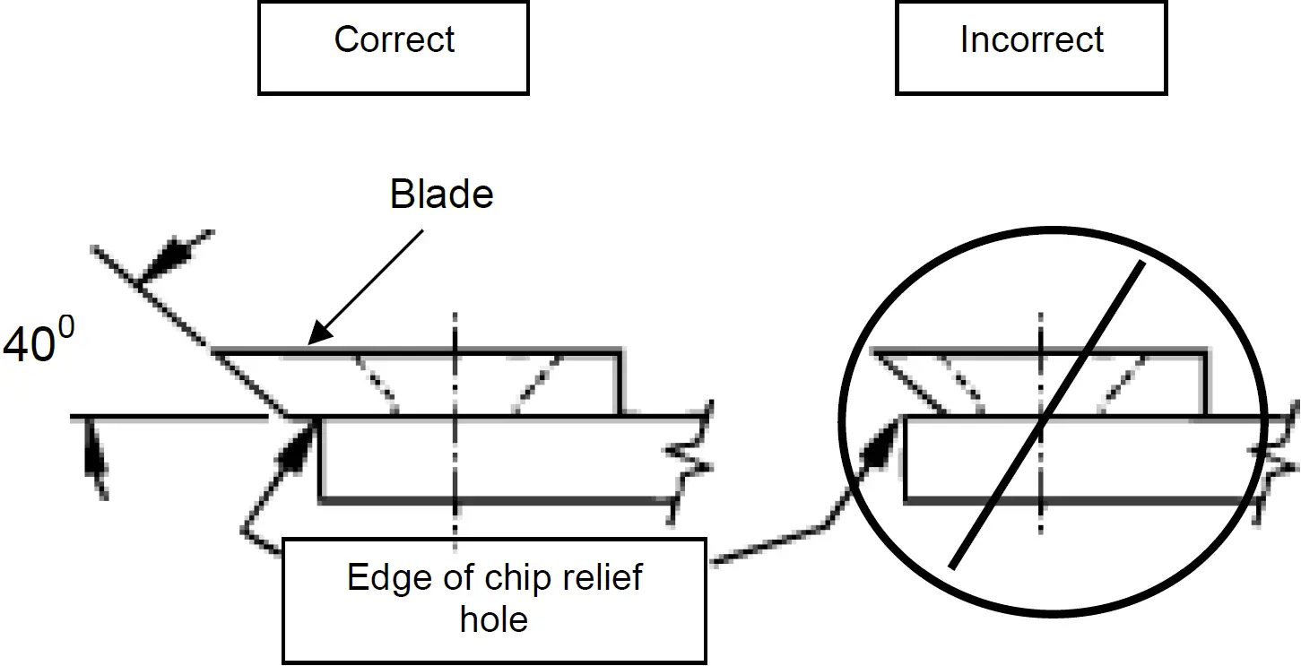
- Sharpen blade by lightly grinding the cutting edge of the blade at 40 degrees. It is not necessary to remove all nicks from the cutting edge. CAUTION: Be careful to avoid heat buildup in the blade during sharpening. This will reduce its heat-treated hardness properties and will reduce blade life. Evidence of too much heat build-up is a change of color along the sharpened edge.
- The same chipper blade can be sharpened several times. However, blade replacement is required when blade no longer overhangs the chip relief hole in the impeller back plate, or if increased vibration occurs.
- Chipper blade installation is in reverse order of removal.
For Shim Washers: If gap is less than 0.040″(0.51mm), add 0.060″(1.52mm) thick shim washer (P/N 890130) and/or 0.020″ ( 1.02mm) thick shim washer (P/N 890131), whichever is required. If gap is more than 0.080″(2.03mm), remove one or more shim washers as needed to obtain correct gap. The chipper will function up to a maximum of 0.125″(3.18mm) gap.
TROUBLESHOOTING
Problem | Possible Cause | Solution |
| Abnormal vibration | Loose or out of balance impeller or loose engine. | Check impeller and replace if required. Check engine. |
| Will not vacuum or has poor vacuum performance | Dirty debris bag. Hose kit cap missing. Clogged nozzle or exhaust. Excessive quantity of debris. Improper nozzle height. | Clean debris bag. Shake bag clean or wash. Check for hose kit cap. Unclog nozzle or exhaust. Allow air to feed with debris. Adjust nozzle height so that it is closer to the debris. |
| Engine will not start | Throttle in off position. Engine not in full choke position. Out of gasoline. Bad or old gasoline. Sparkplug wire disconnected. Dirty air cleaner . | Check stop switches, throttle, choke position and gasoline. Connect spark plug wire. Clean or replace air filter. Or contact a qualified service person. |
| Engine is locked, will not pull over | Debris locked in impeller. Engine problem. | Contact an engine service dealer for engine problems. |
| Nozzle scrapes ground in lowest height setting | Nozzle height out of adjustment. | Adjust nozzle height. |
| No self-propelling | Drive bail not engaged. Drive belt worn or broken. Drive clutch cable out of adjustment or broken. Drive chain off the sprocket. | Engage the drive bail. Check the drive belt. Check the drive clutch cable. |
| Self propelled drive will not release | Improper drive clutch cable adjustment or cable is kinked. | Check the drive clutch cable. |
| Noisy or broken chain | No chain lubrication. Chain misalignment or tension. | Lubricate chain. Check the drive chain. |
| Unit does not free-wheel backwards | None. | Push the unit slightly forward then the unit will free-wheel. |
| Too much dust coming from bag | Vacuuming very dry, brittle or small debris. | Switch to felt bag. |
KVSP/TKVSP PARTS DRAWING
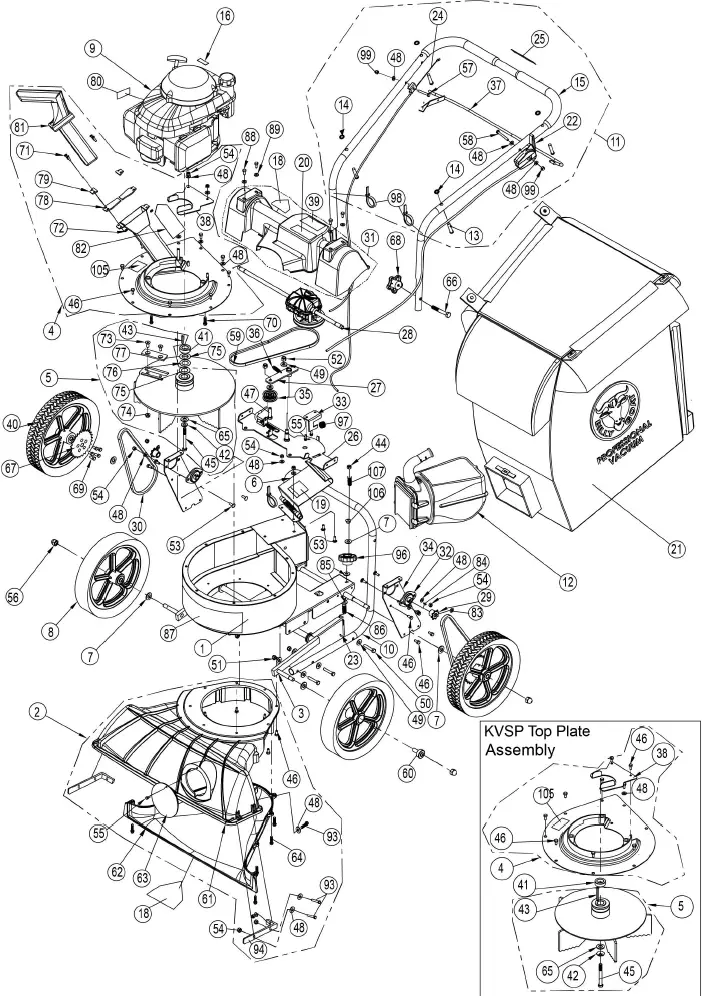
KVSP/TKVSP PARTS LIST
| ITEM NO. | Description | KV601SP/KV601SPF B PART NUMBER | QTY | KV650SPH/KV650SPHF B PART NUMBER | QTY | TKV650SPH/TKV650SPHF B PART NUMBER | QTY |
| 1 | MAIN FRAME HOUSING KV | 891100-S | 1 | 891100-S | 1 | 891100-S | 1 |
| 2 | NOZZLE ASSEMBLY TKV | 891110-S | 1 | 891110-S | 1 | 891110-S | 1 |
| 3 | WA AXLE FRONT KV 2.0 | 891165 | 1 | 891165 | 1 | 891165 | 1 |
| 4 | PLATE TOP WA KVSP | 891101-S | 1 | 891101-S | 1 | 891107-S | 1 |
| 5 | IMPELLER SERRATED 14.25 WA KVSP | 891104-S | 1 | 891104-S | 1 | 891109-S | 1 |
| 6 | DOOR EXHAUST ASSY RAW | 890148-01 | 1 | 890148-01 | 1 | 890148-01 | 1 |
| 7 | WASHER 1/2″ SAE Z/P | 8172011 | 5 | 8172011 | 5 | 8172011 | 5 |
| 8 | WHEEL ASSY 12″ X 2.5″ TREAD | 900509 | 2 | 900509 | 2 | 900509 | 2 |
| 9 | ENGINE 6.5 HP HONDA GSV190AN1L | – | – | 840069 | 1 | 840069 | 1 |
| ENGINE B&S PRO SERIES 875 | 891218 | 1 | – | – | – | – | |
| 10 | LOWER HANDLE KV | 891050 | 1 | 891050 | 1 | 891050 | 1 |
| 11 | HANDLE UPPER KVSP | 891054-S | 1 | 891054-S | 1 | 891054-S | 1 |
| 12 | QUICK DISCONNECT | 890630 | 1 | 890630 | 1 | 890630 | 1 |
| 13 | PIN CLEVIS 3/8″ x 2.125″ LONG | 520120 | 4 | 520120 | 4 | 520120 | 4 |
| 14 | RETAINER | 360279 | 4 | 360279 | 4 | 360279 | 4 |
| 15 | GRIP HANDLE 1″X 9.5″ LG | 430342 | 2 | 430342 | 2 | 430342 | 2 |
| 16 | LABEL HOT ENGINE EN/SP | 100261 | 1 | – | – | – | – |
| 17 | |||||||
| 18 | LABEL WARNING DANGER | 400424 | 2 | 400424 | 2 | 400424 | 2 |
| 19 | LABEL DANGER FLYING DEBRIS | 810736 | 1 | 810736 | 1 | 810736 | 1 |
| 20 | LABEL SAFETY PROTECT READ MANUAL | 100346 | 1 | 100346 | 1 | 100346 | 1 |
| 21 | BAG DEBRIS NO ZIPPER KV | 891132 | 1 | 891132 | 1 | 891132 | 1 |
| BAG FELT W/SKIRT KV (FB MODELS) | 891211 | 1 | 891211 | 1 | 891211 | 1 | |
| 22 | CABLE THROTTLE ASSY 42″ W/CHOKE | 891036 | 1 | 891027 | 1 | 891027 | 1 |
| 23 | J BOLT 3/8-16 X 6″ | 891071 | 1 | 891071 | 1 | 891071 | 1 |
| 24 | CABLE CLUTCH DRIVE ASSY 40″ KVSP | 891032 | 1 | 891032 | 1 | 891032 | 1 |
| 25 | LABEL CLUTCH VQ | 900328 | 1 | 900328 | 1 | 900328 | 1 |
| 26 | BRACKET TRANS MOUNT WA KV | 891106 | 1 | 891106 | 1 | 891106 | 1 |
| 27 | ARM IDLER DRIVE WA KV | 891105 | 1 | 891105 | 1 | 891105 | 1 |
| 28 | TRANS SINGLE SPEED W/DIFF | 891020 | 1 | 891020 | 1 | 891020 | 1 |
| 29 | SPROCKET 8 TOOTH #43 OR #65 | 891022 | 2 | 891022 | 2 | 891022 | 2 |
| 30 | CHAIN #43 X 58 PITCHES | 891023 | 2 | 891023 | 2 | 891023 | 2 |
| 31 | GUARD DRIVE KV | 891004-S | 1 | 891004-S | 1 | 891004-S | 1 |
| 32 | BEARING 1/2″ PRESSED STEEL HOUSING | 891025 | 2 | 891025 | 2 | 891025 | 2 |
| 33 | BRACKET TRANS FIX KV | 891012 | 1 | 891012 | 1 | 891012 | 1 |
| 34 | PLATE CHAIN REINFORCE KV | 891014 | 2 | 891014 | 2 | 891014 | 2 |
| 35 | PULLEY IDLER 2″ OD X 3/8″ ID | 840087 | 1 | 840087 | 1 | 840087 | 1 |
| 36 | SPRING TENSION | 800242 | 1 | 800242 | 1 | 800242 | 1 |
| 37 | BAIL CLUTCH WA KVSP | 891102 | 1 | 891102 | 1 | 891102 | 1 |
| 38 | BRACKET IDLER BELT FINGER KV | 891028 | 1 | 891028 | 1 | 891028 | 1 |
| 39 | LABEL DANGER GUARD | 900327 | 1 | 900327 | 1 | 900327 | 1 |
| 40 | WHEEL ASSY SP 26T SPROCKET | 890242 | 2 | 890242 | 2 | 890242 | 2 |
| 41 | SPACER 1.50OD X .890ID X .5 THK | – | – | 840083 | 1 | 840083 | 1 |
| 42 | WASHER LOCK 3/8 ST MED | 8177012 | 1 | 8177012 | 1 | 8177012 | 1 |
| 43 | SQ KEY 2.125 X .187 | 9201087 | 1 | 9201087 | 1 | 9201087 | 1 |
| 44 | NUT LOCK 3/8-16 THIN | 8161042 | 1 | 8161042 | 1 | 8161042 | 1 |
| 45 | SCREWCAP 3/8-24 x 3 1/2 GR. 8 W/PATCH | 440151 | 1 | 440151 | 1 | 440151 | 1 |
| 46 | SCREWCAP 1/4 – 20 x 5/8 HWH | 890359 | 26 | 890359 | 26 | 890359 | 24 |
| 47 | BOLT IDLER 3/8-16 X 1 1/2 | 800888 | 1 | 800888 | 1 | 800888 | 1 |
| 48 | WASHER 1/4″ SAE ZP | 8172007 | 17 | 8172007 | 17 | 8172007 | 17 |
| 49 | WASHER 5/16 FLATWASHER Z/P | 8171003 | 19 | 8171003 | 19 | 8171003 | 19 |
| 50 | SCREWCAP 5/16-18 X 1.75 ZP | 8041031 | 8 | 8041031 | 8 | 8041031 | 8 |
| 51 | NUT LOCK 5/16-18 | 8160002 | 8 | 8160002 | 8 | 8160002 | 8 |
| 52 | NYLON INSERT LOCKNUT, 3/8-16 UNC | 8160003 | 2 | 8160003 | 2 | 8160003 | 2 |
| 53 | SCREWCAP 1/4-20 X 3/4″ | 8041004 | 2 | 8041004 | 2 | 8041004 | 2 |
| 54 | NYLON INSERT LOCKNUT, 1/4-20 UNC | 8160001 | 12 | 8160001 | 12 | 8160001 | 15 |
| 55 | SCREWCAP #10-14 X 3/4″ HWH ZP | 891043 | 3 | 891043 | 3 | 891043 | 3 |
| 56 | 1/2-13 CAP NUT NP W/PATCH | 890530 | 4 | 890530 | 4 | 890530 | 4 |
| 57 | SCREWCAP 1/4″-20 X 1 1/2″ HCS ZP | 8041008 | 1 | 8041008 | 1 | 8041008 | 1 |
| 58 | SCREWCAP 1/4-20×2″ | 8041010 | 1 | 8041010 | 1 | 8041010 | 1 |
| 59 | BELT 3V315 | 891026 | 1 | 891026 | 1 | 891026 | 1 |
| 60 | BEARING BALL FLANGED | 900774 | 4 | 900774 | 4 | 900774 | 4 |
| 61 | NOZZLE TOP HALF KV | 891002 | 1 | 891002 | 1 | 891002 | 1 |
| 62 | NOZZLE BOTTOM HALF KV | 891003 | 1 | 891003 | 1 | 891003 | 1 |
| 63 | PLUG HOUSING KD LB | 900146-01 | 1 | 900146-01 | 1 | 900146-01 | 1 |
| 64 | SCREW PLASTIC 1/4-20 X 1 | 891039 | 8 | 891039 | 8 | 891039 | 8 |
| 65 | WASHER 1.5 OD X .453 ID X .25 THK | 440153 | 1 | 440153 | 1 | 440153 | 1 |
| 66 | BOLT CARRIAGE 5/16-18 X 2″ CONE HEAD ZP | 80003918 | 2 | 80003918 | 2 | 80003918 | 2 |
| 67 | SPROCKET 65A26 26 TOOTH | 890238 | 2 | 890238 | 2 | 890238 | 2 |
| 68 | KNOB, 5-LOBE 5/16″-18 FEMALE | 441258 | 2 | 441258 | 2 | 441258 | 2 |
| 69 | SCREW SELF TAP 1/4 x 0.75 | 900505 | 10 | 900505 | 10 | 900505 | 10 |
| 70 | SCREW TAPTITE 3/8 X 2 1/2 | 900564 | 3 | 900564 | 3 | 900564 | 3 |
| 71 | SCREWCAP #10-24 X 5/8″ | – | – | – | – | 8059135 | 4 |
| 72 | NYLON INSERT LOCKNUT 10-32 UNF ZINC | – | – | – | – | 8164005 | 4 |
| 73 | SCREW SOCKET HD 5/16-18 X 3/4 GR. 8 | – | – | – | – | 890103 | 2 |
| 74 | NUT KEPS 5/16-18 | – | – | – | – | 890104 | 2 |
| 75 | WASHER SHIM 0.875 ID X 0.060 | – | – | – | – | 891065 | 2 |
| 76 | WASHER SHIM 0.875 ID X 0.020 | – | – | – | – | 891041 | 0-3 |
| 77 | BLADE CHIPPER KD501 | – | – | – | – | 890101 | 1 |
| 78 | GUARD FLAPPER | – | – | – | – | 890119 | 2 |
| 79 | PLATE FLAPPER ENTRANCE | – | – | – | – | 890127 | 2 |
| 80 | LABEL SPARK ARRESTOR EN/SP | – | – | 100252 | 1 | 100252 | 1 |
| 81 | TAMPER CHIPPER | – | – | – | – | 890229 | 1 |
| 82 | LABEL DANGER CHIPPER | – | – | – | – | 890152 | 1 |
| 83 | CLIP 1/2″ | 350146 | 4 | 350146 | 4 | 350146 | 4 |
| 84 | WOODRUFF KEY 1/8 X 1/2 | 510180 | 2 | 510180 | 2 | 510180 | 2 |
| 85 | WASHER 1/2″ FC | 8171006 | 2 | 8171006 | 2 | 8171006 | 2 |
| 86 | SPRING COMPRESSION | 891072 | 1 | 891072 | 1 | 891072 | 1 |
| 87 | LABEL BADGING KV/TKV | 891214 | 1 | 891214 | 1 | 891215 | 1 |
| 88 | SCREW SM 1/4 X 3/4 DRILL PT | 510208 | 4 | 510208 | 4 | 510208 | 4 |
| 89 | WASHER 1/4″ SAE BLACK OXIDE | 510193 | 4 | 510193 | 4 | 510193 | 4 |
| 91 | |||||||
| 92 | CARRIAGE BOLT 1/4″-20 X 3/4″ | 8024021 | 4 | 8024021 | 4 | 8024021 | 4 |
| 93 | SCREWCAP 1/4-20 X 1″ HCS ZP | 8041006 | 6 | 8041006 | 6 | 8041006 | 6 |
| 94 | KV NOZZLE BRACKET | 891208 | 2 | 891208 | 2 | 891208 | 2 |
| 96 | KNOB 3/8-16 RED | 891070 | 1 | 891070 | 1 | 891070 | 1 |
| 97 | SPRING LEVER GZ | 610429 | 1 | 610429 | 1 | 610429 | 1 |
| 98 | TY WRAP | 900407 | 4 | 900407 | 4 | 900407 | 4 |
| 99 | NUT 1/4-20 ACORN | 840071 | 2 | 840071 | 2 | 840071 | 2 |
| 105 | LABEL MADE IN U.S.A. | 520116 | 1 | 520116 | 1 | 520116 | 1 |
| 106 | GROMMET FLANGE 1/2″ MOLDED | 830176 | 1 | 830176 | 1 | 830176 | 1 |
| 107 | SPRING COMPRESSION | 400332 | 1 | 400332 | 1 | 400332 | 1 |


