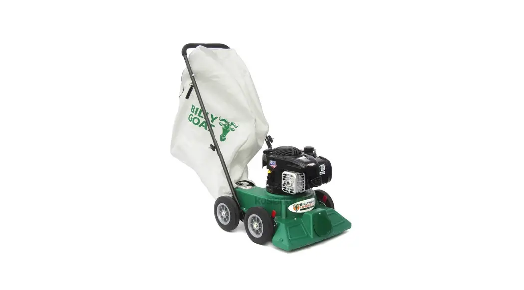
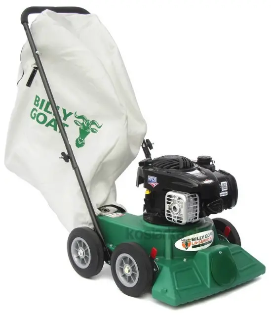
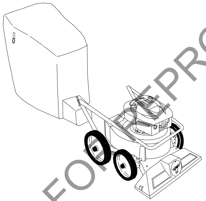
![]() LB352 LB Vacuum Cleaner
LB352 LB Vacuum Cleaner
Instruction Manual
LB352
Beginning Serial #: 071621001
Accessories
| HOSE KIT |
| (102mm x 3.05m) ,or vacuuming in hard Ilto-reach areas. |
| P/N 900460 |
| HOSE CONNECTOR KIT |
| To connect two lengths of 4” hose (hose not included). |
| P/N 890045 |
| STANDARD FELT DEBRIS BAGS |
| For use in dusty conditions. |
| P/N 900719 |
| OPTIONAL TURF DEBRIS BAGS |
| For use in leaves and grass in non-dusty conditions. |
| P/N 900722 |
Original Instructions
IMPORTANT- READ CAREFULLY BEFORE USE AND KEEP FOR FUTURE REFERENCE
SPECIFICATIONS
| Engine cc | 140cc |
| Engine type | B & S 500 series |
| Engine model | 09P6020060F1 |
| Engine fuel capacity | .9 qt (.85 L) |
| Engine oil capacity | 18 to 20 oz. (.54-.59 L) |
| Total unit weight | 57# (25.85 kg) |
| Overall length | 47″ (1.19 m) |
| Overall width | 21.5″ (0.55 m) |
| Overall height | 40.5″ (1.02 m) |
| Max. operating slope | 20° |
| Sound in accordance with 2000/14/EEC standards | 97 dBa |
| Sound at operator’s ear | 77 dB. |
| Vibration at the operator position | 5g (5.17m/s) |
SAFETY
![]() WARNING
WARNING![]()
REPRODUCTION
This product can expose you to chemicals including gasoline engine exhaust, which is known to the State of California to cause cancer, and carbon monoxide, which is known to the State of California to cause birth defects or other reproductive harm. For more information go to www.P65Warnings.ca.gov.
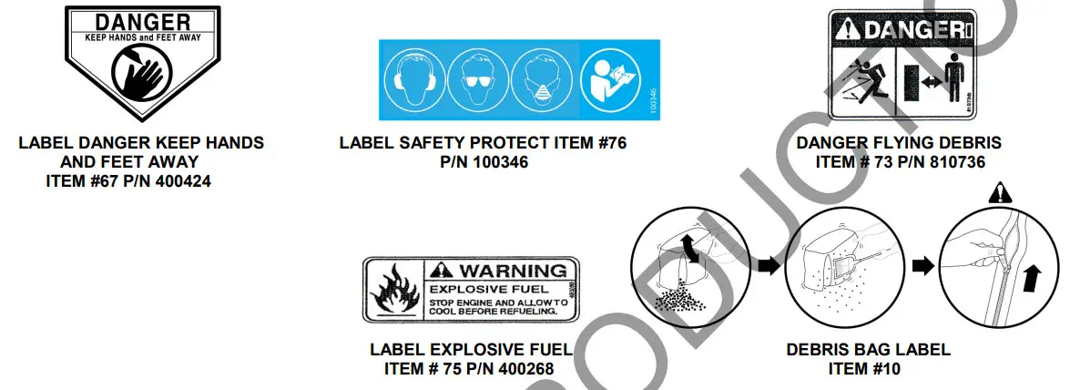
INSTRUCTION LABELS
The labels shown below were installed on your BILLY® GOAT LB Vacuum. If any labels are damaged or missing, replace them before operating this equipment. For your convenience in ordering replacement labels, part numbers are included in the Illustrated Parts List. The correct position for each label may be determined by referring to the Figure and Item numbers shown.
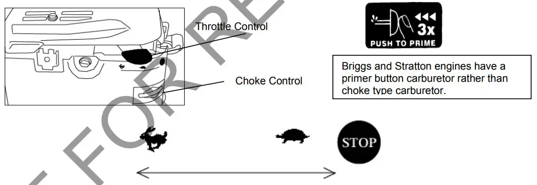
ENGINE CONTROLS AND LABELS
BRIGGS & STRATTON
PACKING CHECKLIST
Your Billy Goat LB Vacuum is shipped from the factory in one carton, completely assembled except for the upper handle and debris bag.
![]() READ all safety instructions before assembling the unit.
READ all safety instructions before assembling the unit.
TAKE CAUTION when removing the unit from the box, the Handle Assembly is attached by cables and folded over.![]() PUT OIL IN THE ENGINE BEFORE STARTING
PUT OIL IN THE ENGINE BEFORE STARTING
PARTS BAG & LITERATURE ASSY
Warranty card P/N- 400972, Owner’s Manual P/N-901015, General Safety and Warnings Manual P/N-100294, Declaration of Conformity P/N-900782, Literature LB Accessories 900714.
Boxing Parts Checklist
- Debris Bag P/N-900718
- Literature Assy P/N-901016
- Briggs & Stratton 500 Series
ASSEMBLY
NOTE: Items in ( ) can be referenced in the Parts Illustration and Parts List on pages 8-9.
Your Billy Goat is shipped from the factory in one carton, completely assembled except for the upper handle and debris bag.
- ROTATE the upper handle into the upward position and securely tighten the knobs. This machine can be stored with handle folded in the down position.
- UNFOLD the debris bag (item 10) and fasten the bag neck onto the exhaust discharge opening.
- ATTACH bag hanger straps to the loops (item 38), preassembled to the upper handle.
- CONNECT spark plug wire.
OPERATION
VACUUMING OPERATION
VACUUM NOZZLE HEIGHT ADJUSTMENT: Nozzle height is raised and lowered by adjusting the front wheel height control.
FOR MAXIMUM PICKUP: Adjust the nozzle close to debris, but without blocking airflow into the nozzle. NOTE: Never bury the nozzle into debris.
CLEARING A CLOGGED NOZZLE & EXHAUST: Turn the engine off and wait for the impeller to stop completely and disconnect the spark plug wire. Wear durable gloves, and remove clogs. Danger, the clog may contain sharp materials. Reconnect the spark plug wire.
DEBRIS BAG
Debris bags are normal replaceable wear items.
NOTE: Frequently empty debris to prevent bag overloading with more weight than you can lift.
An optional bag and dust cover are available for use where debris will be vacuumed in dusty conditions (see “Accessories” on page 1). DO NOT place the bag on or near a hot surface, such as the engine. Run engine at 1/2 throttle for first 1/2 hour to condition new bag. Your new bag requires a break-in period to condition the pores of the material against premature blockage. The entire bag surface serves as a filter and must be able to breathe for good vacuum performance. Be sure the engine has come to a complete stop before removing or emptying the bag.
This vacuum is designed for picking up trash, organic material, and other similar debris (see “Safety and General Operation” manual).
However, many vacuums are used where dust is mixed with trash. Your unit can intermittently vacuum in dusty areas. Dust is the greatest cause of lost vacuum performance. Following these rules will help maintain your machine’s ability to vacuum in dusty conditions:
- Run the machine at idle to quarter throttle.
- The debris bag must be cleaned more frequently. A vacuum with a clean, pillow-soft bag will have good pickup performance.
One with a dirty, tight bag will have poor pickup performance. If dirty, empty the debris and vigorously shake bag free of dust. - Machine or pressure-wash debris bag if normal cleaning does not fully clean the bag. The bag should be thoroughly dry before use.
Having one or more spare debris bags is a good way to reduce downtime while dirty bags are being cleaned.
DO NOT leave debris in the bag while in storage
COMPOST
Vacuumed leaves, grass, and other organic material from your own yard can be emptied into a pile or composter to provide enriched soil for later use as fertilizer in gardens and flower beds. NOTE: Allow green chips to dry before spreading them around living plants.
MAINTENANCE
NOTE: Items in ( ) can be referenced in the Parts Illustration and Parts List on pages 8-9.
PERIODIC MAINTENANCE
Periodic maintenance should be performed at the following intervals:
| Maintenance Operation | Every Use (Daily) | Every 5 Hrs (Daily) |
| Inspect for loose, worn or damaged parts | • | |
| Clean Debris bag | • | |
| Check bag strap tightness | • | |
| Engine (See Engine Manual) | ||
| Check for excessive vibration | • |
IMPELLER REMOVAL
- Wait for the engine to cool and disconnect the spark plug.
- Drain fuel and oil from the engine.
- Remove the bag and remove the upper handle.
- Invert and support the machine without placing the weight of the machine on the engine’s recoil starter.
- Remove rear wheels (item 11), and bolt axle bracket (item 48), one on each side, closest to the middle inlet plate (item 3), washer (item 57), and nut (item 49).
- Remove the intake wrapper assembly (item 2) and middle inlet plate (item 3), eight screws, and eight nuts.
- Remove the impeller bolt (item 37) and lock the washer (item 36).
- Lift the impeller free of the engine.
- If the impeller does not remove easily, obtain a 1″ (25.4mm) longer bolt of the same diameter and thread type as the impeller bolt. Thread longer bolt by hand into crankshaft until bolt bottoms. Using a suitable gear or wheel puller against the bolt head and impeller back-plate (near the blades), remove the impeller from the shaft.
- Reinstall the new impeller, impeller bolt, and lock washer in reverse order. Torque impeller bolt to 33-38 ft-lbs (45-52 N.m).
TROUBLESHOOTING
| Problem | Possible Cause | Solution |
| Abnormal vibration | Lose or out of balance impeller or ,,, loose engine. | Check the impeller and replace it if required. Check engine. |
| Will not vacuum “or h\atscaoi/ vacuum performance | Dirty debris bag. Nozzle height set too high or low. The Hose kit cap missing. Clogged nozzle or exhaust. An excessive quantity of debris. | Clean debris bag. Shake the bag clean or wash it. Adjust nozzle height. Check for the hose kit cap. Unclog the nozzle or exhaust. Allow air to feed with debris. |
| Erigine4fil not start | Throttle in off position. Out of gasoline. Bad or old gasoline. The spark plug wire was disconnected. Dirty air cleaner. | Check throttle. Connect spark plug wire. Clean or replace the air filter. Or contact a qualified service person. |
| The engine is locked, but will not. Pullover | Debris locked in the impeller. Engine problem. | See page 6. Contact an engine service dealer for engine problems. |
| Nozzle scrapes ground in the lowest height setting | Nozzle height out of adjustment. | Adjust nozzle height (See “NOZZLE HEIGHT ADJUSTMENT” for hard surfaces on page 6.) |
LB PARTS DRAWING
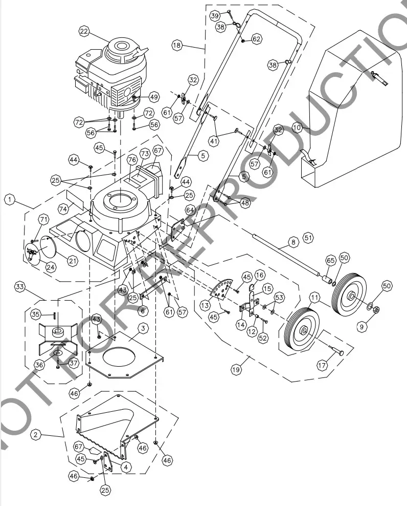
LB PARTS LIST
| ITEM NO. | DESCRIPTION | LB352 Part No. | QTY |
| 1 | HOUSING ASSY | 900590-04 | 1 |
| 2 | WRAPPER-INTAKE ASSY | 900607-04 | 1 |
| 3 | PLATE MIDDLE INLET | 900418 | 1 |
| 4 | PLATE WRAPPER | 900413 | 2 |
| 5 | HANDLE LOWER | 900483 | 2 |
| 6 | BRKT, INTERNAL SUPPORT, LB | 900826 | 2 |
| 8 | AXLE SHAFT | 900818 | 1 |
| 9 | NUT JAM 1/2-13 ZP | 8162005 | 2 |
| 10 | BAG DEBRIS | 900719 | 1 |
| 11 | WHEEL 8″ x 0.5″ BRG | 350236 | 4 |
| 12 | SPACER | 900384 | 2 |
| 13 | PLATE- HT ADJ. | 900414 | 2 |
| 14 | AXLE ARM- HT. ADJ. | 900416 | 2 |
| 15 | ARM ASSY – HT ADJ. | 900417 | 2 |
| 16 | TIP -HT. ADJ. | 900459 | 2 |
| 17 | SCREWCAP 1/2″ -13 X 2 1/2″ HCS ZP | 8041100 | 2 |
| 18 | HANDLE – UPPER ASSY | 900777 | 1 |
| 19 | HT. ADJ. ASSY | 900820 | 2 |
| 20 | SPACER FRONT WHEEL | 900819 | 2 |
| 21 | PLUG | 900146-01 | 1 |
| 22 | ENGINE BRIGGS 500 SERIES | 901012 | 1 |
| 24 | LABEL LOGO SMALL FRAME | 441152 | 1 |
| 25 | WASHER 1/4 SAE | 8172007 | 13 |
| 26 | SCREWCAP 5/16-16 X 1 1/4 | 8041029 | 1 |
| 30 | WASHER 1/2″ FLAT KD WHEEL MTG | 900230 | 4 |
| 32 | KNOB-FOLDING HANDLE | 900456 | 2 |
| 33 | IMPELLER ASSY | 900421 | 1 |
| 35 | KEY-3/16 SQ. X 1 1/4″ | 9201080 | 1 |
| 36 | WASHER LOCK 7/16 S/T MED | 8177013 | 1 |
| 37 | SCREWCAP 7/16-20 X 1″ HCS GR. 8 W/PATCH | 510213 | 1 |
| 38 | BAG LOOP | 800178 | 2 |
| 39 | SCREW CAP 1/4-20 X 1 1/4″ | 8041007 | 2 |
| 41 | BOLT CARRIAGE 5/16-18×2 1/4″ | 900466 | 2 |
| 43 | NUT LOCK 1/4 – 20 HEX ZP | 8160001 | 5 |
| 44 | SCREWCAP 1/4 -20 X 1″ | 8041006 | 2 |
| 45 | SCREWCAP 1/4-20 X 3/4″ | 8041004 | 13 |
| 46 | NUT LOCK WASHER 1/4-20 | 900453 | 10 |
| 48 | SCREWCAP 5/16-18 X 1 1/4″ | 8041029 | 4 |
| 49 | NUT LOCK 5/16-18 HEX ZP | 8160002 | 3 |
| 50 | WASHER FLAT 1/2 SAE (17/32 X 1 1/16 X 3/32) | 8172011 | 8 |
| 52 | SCREWCAP 3/8-16 X 1 1/2″ | 8041052 | 2 |
| 53 | WASHER LOCK 3/8 S/T MED | 8177012 | 2 |
| 55 | WASHER FLAT 3/8 SAE (13/32 X 13/16/ X 1/16) | 8172009 | 2 |
| 56 | SCREW CAP 5/16-18 X 1 1/4 | 8041030 | 3 |
| 57 | WASHER 5/16 SAE (11/32 X 11/16 X 1/16) | 8172008 | 2 |
| 61 | NUT LOCK 5/16-18 | 8160002 | 5 |
| 62 | NUT LOCK 1/4-20 | 8160001 | 2 |
| 64 | BRACKET AXLE | 900487 | 2 |
| 65 | SPACER 1/2 X 5/8 | 900231 | 2 |
| 67 | LABEL DANGER KEEP HANDS AND FEET AWAY | 400424 | 2 |
| 71 | SCREW SELF-TAPPING 10-24 X 1/2 | 8123086 | 1 |
| 72 | WASHER 5/16 FLAT CUT | 8171003 | 3 |
| 73 | LABEL FLYING DEBRIS | 810736 | 1 |
| 74 | LABEL LB BADGING | 901016 | 1 |
| 76 | LABEL SAFETY PROTECT READ MANUAL | 100346 | 1 |

EC Declaration of Conformity
Category
This is to certify that the products listed in this document meet the requirements of the European Community Law, and can carry the CE mark.
Directive:
| Directive: | Guaranteed Sound Power Level | Measured Sound Power Level | Sound Pressure Level at Operator’s Ear (1) | Engine Net Power REPRODUCTION | Hand/Arm Vibration (2) | Mass |
| LB352 | 98 dB(A) | 97 dB(A) | 77 dB(A) | 2.6 kW | 5.17 m/s2 | 25.85 kg |
Manufacturing Place / Keeper of Documentation
| 1803 S.W. Jefferson Lees Summit, MO 640630308 USA | Jeroen Engelen Schepersweg 4a 6049CV Herten, NL |  |
| 10/05/2015 | Ted Melin Engineering Manager | |


