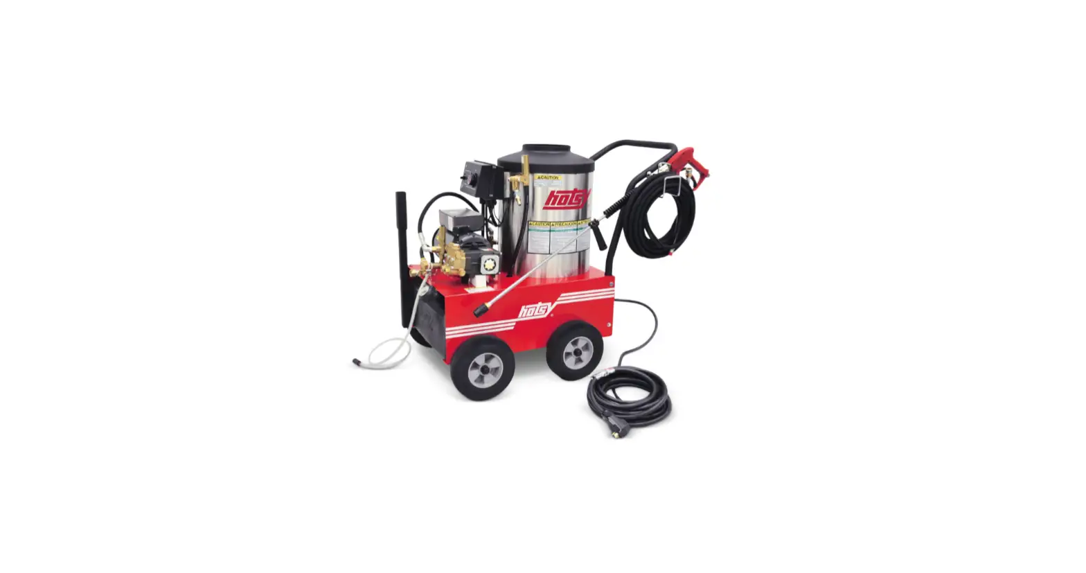
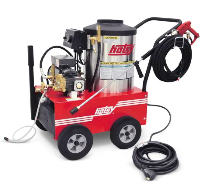
hosty 555SS Hot Water Pressure Washers
 Read instructions carefully before attempting to assemble, install, operate or service this pressure washer. Failure to comply with instructions could result in personal injury and/or property damage!
NOTE: THIS MANUAL IS INTENDED FOR USE WITH THE FOLLOWING MODEL RELEASE ONLY: 555SS
SPECIFICATIONS
- Pump Volume At Pump Head: 2.2 GPM/132 GPH
- Burner Type: Fuel Oil Fired, 214,300 BTU/Hr.
- Burner Fuel Pressure: 200 PSI Max.
- Pump Pressure At Pump Head: 1300 PSI
- Machine Voltage: 120 VAC/60 Hz/1 Ph
- Total Machine Amperage: 20 Amps
- Machine Weight: 280 Lbs.
- Shipping Weight: 315 Lbs.
- Exhaust Stack Size: 8″
- Machine Dimensions: Length = 44″, Width = 26″, Height = 38″
- SERIAL NUMBER
- DATE PURCHASED
- FOR SALES AND SERVICE, PLEASE CONTACT
INTRODUCTION & IMPORTANT SAFETY INFORMATION
Thank you for purchasing this Pressure Washer.
We reserve the right to make changes at any time without incurring any obligation.
Owner/User Responsibility:
The owner and/or user must have an understanding of the manufacturer’s operating instructions and warnings before using this pressure washer. Warning information should be emphasized and understood. If the operator is not fluent in English, the manufacturer’s instructions and warnings shall be read to and discussed with the operator in the operator’s native language by the purchaser/owner, making sure that the operator com-prehends its contents. Owner and/or user must study and maintain for future reference the manufacturers’ instructions. The operator must know how to stop the machine quickly and understand the operation of all controls. Never permit anyone to operate the engine without proper instructions.
SAVE THESE INSTRUCTIONS
This manual should be considered a permanent part of the machine and should remain with it if machine is resold. When ordering parts, please specify model and serial number. Use only identical replacement parts. This machine is to be used only by trained operators.
IMPORTANT SAFETY INFORMATION
WARNING: To reduce the risk of injury, read operating instruc-tions carefully before using.
- Read the owner’s manual thoroughly. Failure to follow in-structions could cause malfunc-tion of the machine and result in death, serious bodily injury and/or property damage.
- Know how to stop the machine and bleed pressure quickly. Be thoroughly familiar with the controls.
- Stay alert — watch what you are doing.
- All installations must comply with local codes. Contact your electrician, plumber, utility company or the selling distributor for specific details. If your machine is rated 250 volts or less, single phase will be provided with a ground fault circuit interrupter (GFCI). If rated more than 250 volts, or more than single phase this product should only be connected to a power supply receptacle protected by a GFCI.
DANGER: Improper connection of the equipment-grounding conductor can result in a risk of elec-trocution. Check with a qualified electrician or service personnel if you are in doubt as to whether the outlet is properly grounded. Do not modify the plug provided with the product – if it will not fit the outlet, have a proper outlet installed by a qualified electrician. Do not use any type of adaptor with this product
WARNING: Must be plugged into properly wired three hole grounded outlet that accommodates plug on power cord. Failure to comply could result in electrical shock.
- To protect the operator fromelectrical shock, the machine must be electrically grounded. It is the responsibility of the owner to connect this machine to a UL grounded receptacle of proper voltage and amperage ratings. Do not spray water on or near electrical components. Do not touch machine with wet hands or while standing in water. Always dis-connect power before servicing.
WARNING: Flammable liquids can create fumes which can ig-nite, causing property damage or severe injury.
WARNING: Risk of explosion — Operate only where open flame or torch is permitted.
- In oil burning models, use only kerosene, No. 1home heating fuel, or diesel. If diesel is used, add a soot remover to every tankful.
WARNING: Risk of fire — Do not add fuel when the product is operating or still hot.
WARNING: Do not use gasoline crankcase draining or oil con-taining gasoline, solvents or alcohol. Doing so will result in fire and/or explosion.
- Oil burning appliances shall be installed only in locations where combustible dusts and flammable gases or vapors are not present. Do not store or use gasoline near this machine.
- Do not allow acids, caustic or abrasive fluids to pass through the pump.
- Never run pump dry or leave spray gun closed longer than 1-2 minutes.
- Keep operating area clear of all persons.
WARNING: High pressure spray can cause paint chips or other particles to become airborne and fly at high speeds. To avoid personal injury, eye, hand and foot safety devices must be worn. Eye, hand, and foot protec-tion must be worn when using this equipment.
WARNING: This machine ex-ceeds 85 db appropriate ear protection must be worn.
WARNING: Hot discharge fluid. Do not touch or direct discharge stream at persons.
WARNING: This machine pro-duces hot water and must have insulated components attached to protect the operator.
WARNING: Risk of injury. Hot surfaces can cause burns. Use only designated gripping areas of spray gun and wand. Do not place hands or feet on non-insu-lated areas of the pressure washer.
- To reduce the risk of injury, close supervision is necessary when a machine is used near children. Do not allow children to operate the pressure washer. This machine must be attended during operation.
WARNING: Grip cleaning wand securely with both hands before starting. Failure to do this could result in injury from a whipping wand.
- Never make adjustments on machine while in operation.
- Be certain all quick coupler fittings are secured before using pressure washer.
WARNING: High pressure devel-oped by these machines will cause personal injury or equip-ment damage. Keep clear of nozzle. Use caution when oper-ating. Do not direct discharge stream at people, or severe in-jury or death will result.
WARNING: Protect machine from freezing.
- To keep machine in best operating conditions, it is important you protect machine from freezing. Failure to protect machine from freezing could cause malfunction of the machine and result in death, serious bodily injury, and/or property damage. Follow storage instructions specified in this manual.
- Inlet water must be clean fresh water and no hotter then 90°F.
- WARNING: Risk of asphyxiation. Use this product only in a well ventilated area.
- Avoid installing machines in small areas or near exhaust fans. Adequate oxygen is needed for combustion or dangerous carbon monoxide will result.
- Manufacturer will not be liable for any changes made to our standard machines or any components not purchased from us.
- The best insurance against an accident is precau-tion and knowledge of the machine.
WARNING: Be extremely careful when using a ladder, scaffolding or any other relatively unstable location. The cleaning area should have adequate slopes and drainage to reduce the pos-sibility of a fall due to slippery surfaces. - Do not overreach or stand on unstable support. Keep good footing and balance at all times.
- Do not operate this machine when fatigued or under the influence of alcohol, prescription medications, or drugs.
WARNING: Do not spray ma-chine or any people, animals or electrical parts. Follow the maintenance instructions specified in the manual.
COMPONENT IDENTIFICATION
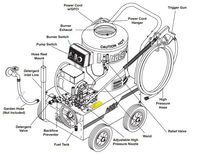
- Pump — Delivers a specific gpm to the high pressure nozzle which develops pressure.
- Spray Gun — Controls the application of water and detergent onto cleaning surface with trigger device. Includes safety latch.
- Detergent Valve — Allows you to siphon and mix detergents.
- Wand — Must be connected to the spray gun.
- High-Pressure Hose — Connect one end to water pump high pressure discharge nipple and the other end to spray gun.
- Relief valve — Secondary pressure release in the unlikely event the unloader valve fails.
- Unloader Valve — Safety device which, when the spray gun closes, prevents over pressurization.
ASSEMBLY & INSTALLATION INSTRUCTIONS
ASSEMBLY
Unpacking
Unpack carefully. Wear safety glasses or goggles while unpacking, assembling or operating pressure washer. If there are missing components or hidden damage immediately contact distributor or carrier concerning discrepancies.
- Cut strapping band from pressure washer and pallet.
- Remove pressure washer from pallet.
Parts Included
- Pressure Washer
- Pressure Hose
- Wand Assembly
- Operating Instructions and Parts Manual
- Teflon Tape
Tools Required
- 10″ Adjustable Crescent Wrench (2 ea.)
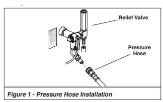
Pressure Hose
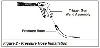
- When assembling, use teflon tape on all plumbing connections to prevent leakage.
- Install high pressure hose on machine as shown in Figure 1.

- Assemble pressure hose onto trigger gun/wand assembly as shown in Figure 2.

- Make sure that all plumbing connections are tight.
INSTALLATION
Getting Started
IMPORTANT: Proper initial installation of equipment will assure more satisfactory performance, longer service life and lower maintenance cost.
IMPORTANT: The use of a backflow preventer on the water supply hose is recommended and may be required by local code. The pressure washer should be run on a level surface where it is not readily influenced by outside sources such as strong winds, freezing temperatures, rain, etc. The pressure washer should be located to assure easy access for filling of fluids, adjustments and maintenance. Normal precautions should be taken by the operator to prevent moisture from reaching the pressure washer. It is recommended that a partition be made between the wash area and the pressure washer to prevent direct spray from the wand coming in contact with the pressure washer. Moisture reaching the equipment will reduce the pressure washer’s life. All installations should comply with the local codes covering such installations. Venting
CAUTION: All venting must be in accordance with ap-plicable federal and state laws, and local ordinances. Consult local heating contractors. If the pressure washer is to be used in an enclosed area, a flue must be installed to vent burner exhaust to the outside atmosphere. Exhaust gases should not be vented into a wall, a ceiling, or a concealed space of a building. Be sure the flue is the same size as the burner exhaust vent on the pressure washer lid. Poor draft will cause the pressure washer to soot and not operate properly. When selecting the location for installation, beware of poorly ventilated locations or areas where exhaust fans may cause an insufficient supply of oxygen. Proper combustion can only be obtained when there is a sufficient supply of oxygen available for the amount of fuel being burned. If it is necessary to install the machine in a poorly ventilated area, outside fresh air may have to be piped to the burner and a fan installed to bring sufficient air into the machine. Locate the pressure washer so that the flue will be as straight as possible and protrude through the roof at a proper height and location to provide adequate draft. This oil fired pressure washer must have a draft regulator installed in the flue (available from most heating contractors). A draft regulator will permit proper upward flow of exhaust flue gases.
INSTALLATION & OPERATION INSTRUCTIONS
Burner Air Adjustment
The oil burner on this machine is preset for operation at altitudes below 500 feet. If operated at higher altitudes, it may be necessary to adjust the air band for a #1 or #2 smoke spot on the Bacharach scale. To adjust, start machine and turn burner ON. Loosen two locking screws found on the air band and close air band until black smoke appears from burner exhaust vent. Note air band position. Next, slowly open the air band until white smoke just starts to appear. Turn air band halfway back to the previously noted position. Tighten locking screws. For higher altitudes, the air band opening may need to be increased; for lower altitude, the .air band may need to be decreased. For higher humidity, the air band opening may need to be increased; for lower relative humidity, the .air band may need to be decreased. For higher ambient temperatures the air band opening may need to be increased; for lower ambient tempera-tures, the air band opening may need to be decreased. Adjust to your operating location’s environment as-needed for best smoke spot and performance compliant with local, state, and federal regulations.
OPERATION INSTRUCTIONS
OPERATION
Before Starting
WARNING: Check hoses, trigger guns, fittings, and fuel connections daily for signs of wear, cracks and looseness, and replace as required.
- Read all manuals provided with this pressure washer. Become familiar with location and function of all operating and safety controls.
- Connect water supply hose to the standard garden hose connector. The water faucet and supply hose must be capable of providing 3.0 GPM.
- Fill fuel tank. Use kerosene, #1 grade home heating oil, #1 or #2 diesel fuel. DO NOT USE GASOLINE, CRANKCASE OIL RESIDUALS OR WASTE OIL.
- Check pump oil level.
- If detergents are to be used, only use detergents intended for pressure washers. Follow instructions on the detergent container.
Electrical Connections
WARNING: Make sure all switches and controls are in the OFF position prior to plugging in.
CAUTION: This pressure washer is equipped with a UL approved ground fault circuit interrupter (GFCI) power cord. Use UL grounded type receptacles of proper voltage and amperage ratings. Where a properly grounded receptacle is not available, it is the personal responsibility of the owner to have one installed. Always disconnect power before servicing your pressure washer. Connect electrical cord and test the GFCI using the reset and test procedures provided on the GFCI device. The GFCI must be reset and tested with every use. Do not use machine if the GFCI device fails test. Pressure Nozzle/Trigger Lock Installation
IMPORTANT: If the pressure washer has not been used for an extended period of time, remove the nozzle from the end of the wand and turn on water supply. Allow water to run from the end of the wand until clear.
- Install adjustable pressure nozzle on end of the wand.
See Figure 4.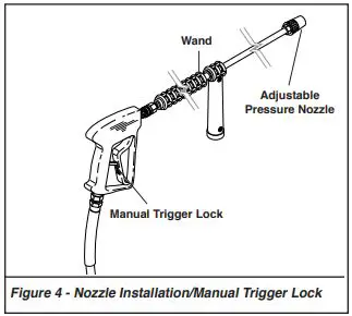 IMPORTANT: The trigger gun provided with this pres-sure washer is equipped with a manual trigger lock to prevent accidental operation of the trigger gun. The trigger lock should be used whenever the trigger gun is not in use.
To Start
IMPORTANT: The water must be turned on before starting. Running the pump dry will cause damage to pump seals and void warranty.
IMPORTANT: DO NOT allow the machine to run in bypass for more than 10 minutes at any one time or damage to pump may occur.
- Turn water on.
- Hold gun firmly, squeeze trigger of trigger gun and turn pump switch ON. Allow air to purge from system.
- If HOT water is desired, turn burner switch ON. Adjust thermostat to desired temperature. The burner will fire immediately with a small puff of smoke. If smoke continues refer to the Troubleshooting Guide in this manual. When the trigger gun is closed the burner will turn off.
To Stop
- If detergents were used, draw clear water through the detergent line to purge detergent.
- If burner was used, turn off burner switch and allow pump to run cold water through coil.
- Push OFF pump switch.
- Turn OFF water supply.
- Squeeze trigger gun open to relieve system pressure.
NOTE: If the machine is unplugged from receptacle, you must reset the GFCI power cord when machine is plugged in. Always test GFCI before each use. See instructions in the Electrical Connections section of this manual.
OPERATION INSTRUCTIONS & CLEANING TECHNIQUES
GENERAL CLEANING TECHNIQUES
Warning: Pressure washers produce a kickback. To prevent personal injuries due to falls use auxiliary safety equipment. The detergent injector valve operates by reducing the volume of water, thus a vacuum is achieved and detergent is drawn into the system. DO NOT reduce the water inlet flow so much as the pump cavitates because of water starvation. Operating a pump with insufficient water will damage the pump seals.
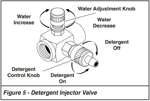
- Insert detergent line and screen into container of detergent.
- Completely open detergent control knob located on the side of the detergent injector valve.
- Start the detergent suction by rotating the water adjustment knob of the detergent injector valve. See Figure 5. Turning the knob counterclockwise will pull detergent into the system. The flow may be observed

- The side control knob can now be adjusted to meter the desired amount of detergent.
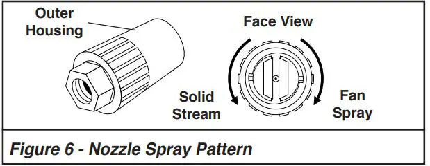
- Select the width of your nozzle spray pattern by turning the black knob on the nozzle. See Figure 6. Pattern can be from 0 degrees through 80 degrees fan spray. Release the trigger of the trigger gun prior to making any spray pattern adjustments.

- Wash from the bottom to the top, using side to side motions. This washes away heavy dirt and allows the detergent to soak as you work toward the top.
- Do not wash at a 90o angle to the work (straight at it). This will allow water to splash back at you and reduces your cleaning power. Wash at a 30o to 60o angle to the work. This will allow the water to splash away from you and the water will wash the dirt away faster and easier.
- Use the width of the spray pattern to wash in a wide path. Overlap spray paths for complete cover-age washing from side to side, using slow, steady motions.
- The nozzle should be 12″ to 24″ from work, closer for tough areas. Be careful on painted or delicate surfaces, the pressure may damage surface if nozzle is too close.
- 10. Small parts should be washed in a basket so the pres-sure does not push them away. Larger, lightweight parts should be clamped down so the pressure does not push them away.
- Turn the side detergent control knob clockwise (CW) for detergent decrease. Wait for detergent to clear. Always rinse with cold water after using detergent. Rinse from the top to the bottom to prevent detergent from dripping onto a rinsed area. For the best results, contact your Hotsy dealer to help you select the best detergent for your application.
STORAGE & MAINTENANCE
STORAGE
Protect from freezing by storing in a heated area, or by flushing the system with antifreeze (use an automotive engine antifreeze or windshield washer solvent to antifreeze). To flush the system with antifreeze, attach a short length of hose to the garden hose connector located on the pump. Place the other end of the hose into a container of antifreeze. Start machine and allow to run until antifreeze flows from the end of the wand. Squeeze and release the trigger of the trigger gun several times to antifreeze the unloader system. Also draw antifreeze through the detergent inlet line to antifreeze the detergent system. For added protection after anti-freezing, disconnect the pressure hose from machine and remove the coil drain plug (refer to Exploded View for location). After coil has drained, replace pressure hose and coil drain plug. If the pressure washer is not to be used for an extended length of time, it is recommended that the system be flushed with antifreeze for rust protection.
MAINTENANCE
WARNING: Unauthorized machine modification or use of non-approved replacement parts may cause personal injury and/or property damage and will void the manufacturer warranty.
Pump
Lubrication: To lubricate pump, use 30W non-detergent oil for pump crankcase. Crankcase must be filled to the full mark on the dipstick or to center of sight glass window found on the side of the pump, refer to Figure 7. During the break-in-period, make sure the oil is changed after the first 25 hours of operation. After that, replace oil every 3 months or 300 hours, whichever comes first.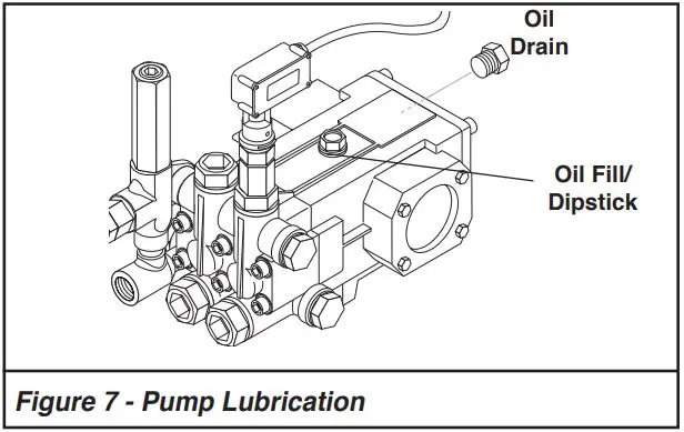
Proper Pump Care
- DO NOT pump acids.
- DO NOT allow pump to run dry.
- Winterize if storing in freezing temperatures, refer to Storage & Maintenance for details.
- Use a water softener on the water system if known to be high in mineral content.
- Use only high quality detergents and follow manu-facturer’s mix recommendations.
- Flush the system with clear water immediately after using detergent solutions.
- Clean filter screen on detergent inlet line periodi-cally.
- Flush the pressure washer system with antifreeze if storing for an extended period of time, refer to Storage & Maintenance for details.
Pump Motor
On a yearly basis, oil pump motor per instructions on motor nameplate.
Unloader Valve
WARNING: The unloader valve on this pressure washer has been factory set and sealed and is a field nonadjustable part. Tampering with the factory setting may cause personal injury and/or property damage, and will void the manufacturer warranty. For replace-ment parts refer to Pump Assembly.
Burner Fuel Filter
Drain any water which has accumulated in fuel filter and clean or replace element as needed. For replacement parts, refer to Burner Assembly.
Heating Coil
Coil Descaling: In hard water areas, scale buildup within the heating coil will occur. Scale deposits will decrease the water temperature rise and may eventually clog the heating coil. Contact your local service center when descaling is needed.
Coil Desooting: Poor grades of fuel oil or inadequate combustion air will cause heavy soot buildup on the outside surface of the heating coil. These deposits will insulate the coil. This will restrict the air flow through the coil, further aggravating the soot buildup. Contact your local service center when desooting is needed.
Relief Valve
WARNING: The relief valve on this pressure washer has been factory set and sealed and is a field non-adjustable part. Tampering with the factory setting may cause personal injury and/or property damage, and will void the manufacturer warranty. For replacement parts refer to Coil Outlet Assembly. If pressure from pump or thermal expansion should exceed safe limits, the relief valve will open, allowing high pressure to be discharged through hose to ground. Caution: Inspect relief valve annually for any obstruction.
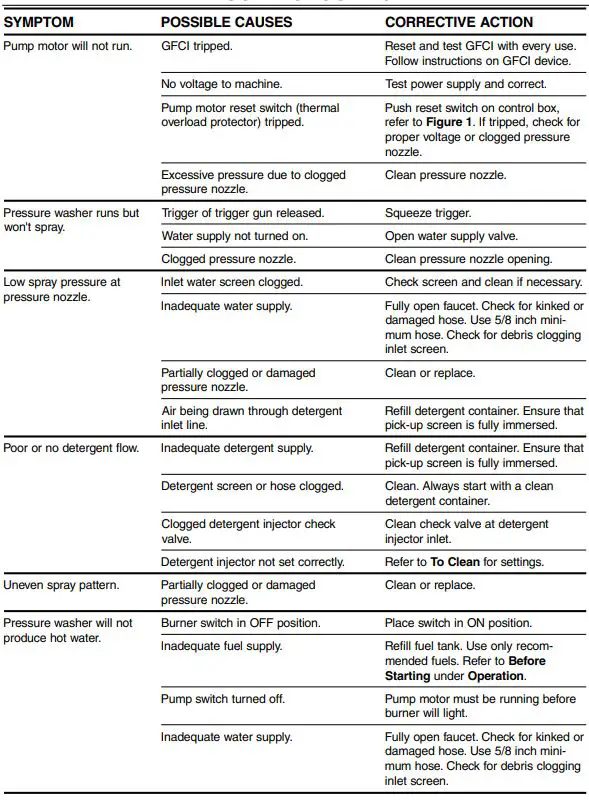
TROUBLESHOOTING
| TROUBLESHOOT | ING | |
| SYMPTOM | POSSIBLE CAUSES | CORRECTIVE ACTION |
| Pressure washer will not produce hot water. | Trigger of trigger gun released. | Squeeze trigger. Water must be spraying for burner to light. |
| Defective pressure switch. | Replace pressure switch. | |
| Fuel valve closed. | Check that fuel valve on fuel tank is open. | |
| Burner motor reset button (thermal overload protector) tripped. | Push reset button on burner motor. If tripped, check for proper voltage. | |
| Clogged fuel filter. | Replace fuel filter. | |
| Thermostat set too low. | Adjust thermostat to desired temp-erature. | |
| Burner smokes. AB | Air bands need to be adjusted. | Readjust air band per the Oil Burner sec- tion under Installation. |
| A) SMOKES AB WHILE UNIT IS RUNNING AB
AB B) SMOKES AT COLD-START WHEN BURNER AB IS OF AB
AB
AB
AB
B | Improper fuel.
Low fuel pressure < 140 PSI Weak fuel pump Fuel filter partially cogged
Soot build up on coils Lime build up in coils Improper burner nozzle Electrode is misaligned
Fuel pressure is to high for clean burn (Fuel PSI above 140 but less than 200) | Use proper fuel.
Adjust fuel pump pressure to specifications.
Check fuel pump pressure. Replace pump if needed. Replace as needed.
Clean coils with soot remover
Clean inside of coils using Hotsy’s coil cleaner. See combustion assembly breakdown. Realign electrodres to specs. Reduce fuel PSI / increase air and band set for cleaner burn without max water heat loss. |
| Poor cleaning | Improper detergent concentration or mixing. | Mix detergent per manufacturer’s instruc- tions. Ensure that powdered detergents are fully dissolved. |
| Wrong detergent for the application. | Select appropriate detergent. | |
| Rinsing with hot water. | A final rinse with cold water will reduce water spotting. |
IMPORTANT
If the pressure washer demonstrates other symptoms or the corrective actions listed do not correct the problem, contact the local authorized Hotsy Service Center. The Hotsy Service Center can be identified by visiting www.hotsy.com
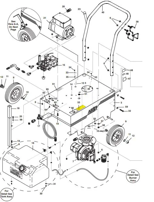
EXPLODED VIEW
EXPLODED VIEW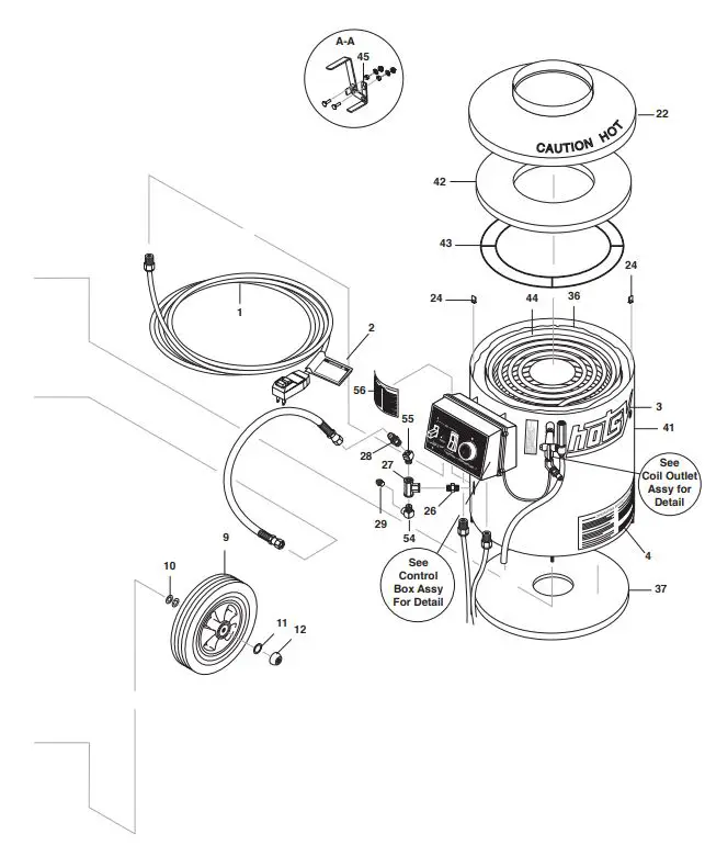
EXPLODED VIEW PARTS LIST
| 1 | 9.802-431.0 | Power Cord w/ GFCI | 1 |
| 2 | 8.932-969.0 | Label, Warning, Svc Cord | 1 |
| 3 | 8.704-654.0 | Label, Hotsy Logo Red | 2 |
| 4 | 8.900-896.0 | Label, Operating Oil Fired Electric. | 1 |
| 5 | 8.911-832.0 | Frame Welded Assy Hotsy 555/680/770 | 1 |
| 6 | 9.802-778.0 | Nut, 5/16″ Whiz Loc Flange | 6 |
| 7 Please See Burner Assembly Page | |||
| 8 | 8.901-106.0 | Label, Hotsy Logo Stripe | 2 |
| 9 | 9.802-274.0 | Wheel & Tire Hard Rubber | 4 |
| 10 | 9.802-810.0 | Washer 5/8″ Flat Sae Zinc | 8 |
| 11 | 8.718-870.0 | Nut, .61 ID, Push Flat | 4 |
| 12 | 9.182-506.0 | Hubcap | 4 |
| 13 | 9.802-104.0 | Bushing, 1″ Snap | 1 |
| 14 | 8.706-731.0 | Bushing, 3/4″ Snap | 1 |
| 24 | 9.802-825.0 | Clip, Retaining U-type | 4 |
| 25 | 8.718-618.0 | Bolt, 5/16-18 x 3/4″, Hh Znc | 1 |
| 26 | 8.757-653.0 | Nipple hex steel 3/8″ NPTF x 3/8″ BSPP | 1 |
| 27 | 8.706-214.0 | Tee, 3/8″ Female Pipe | 1 |
| 28 | 8.757-655.0 | Adapter steel 1/2″ JIC x 3/8″ NPTF(M) | 1 |
| 29 | 8.706-241.0 | Plug, 3/8″, Sq Head, Galv | 1 |
| 30 | 8.718-582.0 | ▲ Bolt 1/4-20 x 1/2″, Nc Hh | 2 | |
| 31 | 9.802-802.0 | ▲ Washer 1/4″ Flat Sae Znc | 2 | |
| 32 | 9.802-716.0 | Bolt, 5/16″ x 2″, Nc Hh | 4 | |
| 33 | 8.709-090.0 | Clamp, Wire/Tube, 0.750D | 2 | |
| 34 | 8.718-588.0 | Screw, 10-24″ x 1/2″, Ph | 2 | |
| 35 | 8.718-857.0 | Nut, 10/24, Whiz Loc Flange | 2 | |
| 36 | 9.802-908.0 | Insulation, Blanket, 18 x 52, Fiberglass | 1 | |
| 37 | 9.802-903.0 | Insulation, Bottom, 16 Od x 4.5, Fiberglass | 1 | |
| 39 | 9.803-098.0 | Holder | 1 | |
| 40 | 8.920-274.0 | Handle | 1 | |
| 41 | 8.911-803.0 | Wrap, Outer Coil Assy S.S., Hotsy 555 | 1 | |
| 16 |
| 53 | 9.800-049.0 | Label, Manufacturers Cleaning Solution | 1 |
| 54 | 8.757-340.0 | Elbow 3/8″, Street 90 DEG, SteeL, W/SLNT | 1 |
| 55 | 8.757-551.0 | Elbow Street Steel 3/8″ 45° | 1 |
| 56 | 8.704-656.0 | Label, Warning, Hww Elec | 1 |
| 57 | 9.198-014.0 | Washer 21/64 x 1″ | 3 |
| 58 | 9.802-776.0 | Nut, 5/16″, Esna, Nc | 3 |
| 59 | 8.718-980.0 | Washer, 5/16″ Flat, Sae | 3 |
| 60 | 8.901-136.0 | Label, Use Hotsy Detergent | 1 |
| 61 | 8.901-135.0 | Label, Caution Winterize | 1 |
| 62 | 8.901-125.0 | Label, Detergent Metering | 1 |
| 63 | 8.901-124.0 | Label, Water Metering | 1 |
| 64 | 8.757-432.0 | Bolt, 1/4-20 X 3/4,Carriage ST CL5 ZNPLT | 2 |
| 65 | 9.802-775.0 | Nut, 1/4″ Flange, Zn | 2 |
| ▲ Not Shown |
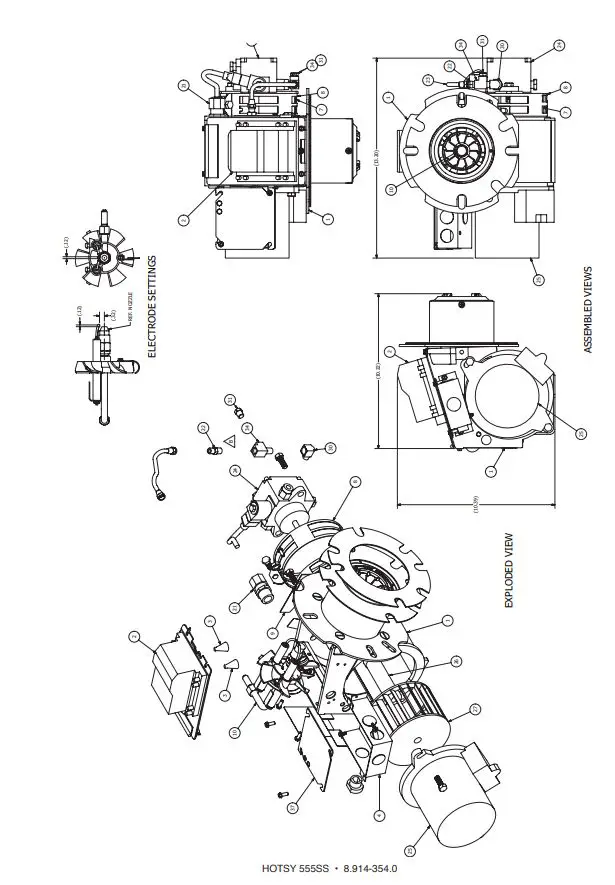
BURNER ASSEMBLY EXPLODED VIEW
BURNER ASSEMBLY EXPLODED VIEW PARTS LIST
| ITEM | PART NO. | DESCRIPTION | QTY |
| 1 | 8.756-181.0 | Burner, MSR 3.75 120V 1T 120V S | 1 |
| 2 | 8.757-199.0 | Hose barb, 1/4″ Barb x 1/4″ M-NPTF, Brass | 1 |
| 3 | 8.757-198.0 | Elbow, 1/4″ Street, Brass | 2 |
| 4 | 8.757-366.0 | Nipple, 1/4″ X 3″, W/SLNT | 1 |
| 5 | 8.757-652.0 | Filter Fuel Hotsy 1/4″ female 1 | |
| 6 | 8.757-205.0 | Hose Barb, 1/4″ Barb x 1/4″ M-NPTF, 90° 1 | |
| 7 | 8.756-179.0 | Fuel Nozzle 1.35 x 80 BZ 1 | |
| 8 | 6.390-126.0 | Clamp Hose, Uni .46-.54 1 | |
| 9 | 8.750-933.0 | Band Hose Clamp, Hose Id 1/8″ – 5/16″ 1 | |
WAYNE BURNER EXPLODED VIEW
Replacement Parts For best performance specify genuine WAYNE replacement parts
WAYNE BURNER PART LIST
Replacement Parts For best performance specify genuine WAYNE replacement parts
| ITEM | PART NO. | DESCRIPTION | QTY |
| 1 | 8.756-443.0 | Tube/Hous-101392-001/ 5A/3.5″/3″I | 1 |
| 2 | 8.700-803.0 | Ignitor- D W/M Plate 120V | 1 |
| 3 | 8.700-678.0 | Spring, Contact | 1 |
| 4 | 8.756-740.0 | Junction Box, MSR, Black Body | 1 |
| 7 | 8.700-707.0 | Air Band Inner “M” | 1 |
| 8 | 8.700-708.0 | Band, Air Outer 8-Hole Mod M | 1 |
| 9 | 8.759-129.0 | Plate Slot Cover | 1 |
| 10 | 8.756-298.0 | Gun Assembly, Burner-RG/*CST/*1 1/4″BB | 1 |
| 22 | 8.758-284.0 | Connector, Male-3/16″ x 1/8″IPT | 1 |
| 23 | 8.700-704.0 | Oil Line Assembly 6″ | 1 |
| 24 | 8.756-290.0 | Pump – Combo/W Solenoid 120V | 1 |
| 25 | 8.756-292.0 | Motor 1/7 HP 120/60 | 1 |
| 26 | 8.700-822.0 | Coupling “M” | 1 |
| 27 | 8.700-726.0 | Fan – 3.12″ x 4.25″D 1/2″ Bore | 1 |
| 30 | 8.758-287.0 | Fitting, Elbow 90* Street 1/8 | 1 |
| 31 | 8.758-285.0 | Plug, Pipe HXHD 1/8″ NPT | 1 |
| 34 | 8.758-286.0 | Tee, Street-1/8 X 1/8 Brass | 1 |
| 35 | 8.759-130.0 | Stopper, #4 Cork | 1 |
| 36 | 8.700-692.0 | Flange Gasket (2 Each) | 2 |
| 37 | 8.756-739.0 | Junction Box, MSR, Black Cover | 1 |
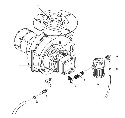
COIL OUTLET ASSEMBLY EXPLODED VIEW & PARTS LIST
| ITEM | PART NO. | DESCRIPTION | QTY | |||
| 6 1 | 8.757-24 0.0 | Manifold, Coil Outlet Discharge, W/Tag | 1 | |||
| 2 | 8.706-241.0 | Plug, 3/8″ Sq Head, Galv | 1 | |||
| 3 | 9.196-012.0 | Screw, 10-24 x 1/4″ Hex Set 1 | ||||
| 4 | 8.757-551.0 | Elbow Street Steel 3/8″ 45° | 1 | |||
| 5 | 8.757-341.0 | Coupler, 3/8″ Plug, Male, Steel/Zinc, W/SLNT | 1 | |||
| 6 | 8.902-433.0 | Valve, Safety Relief VSA | 1 | |||
| 7 | 8.711-785.0 | Hose, 3/8″ Push On, Per Ft | 28″ | |||
| 7 | 8 | 9.800-021.0 | Label, Hot Water Outlet | 1 | ||
| 4 |
5 | |||||
FUEL TANK ASSEMBLY EXPLODED VIEW & PARTS LIST
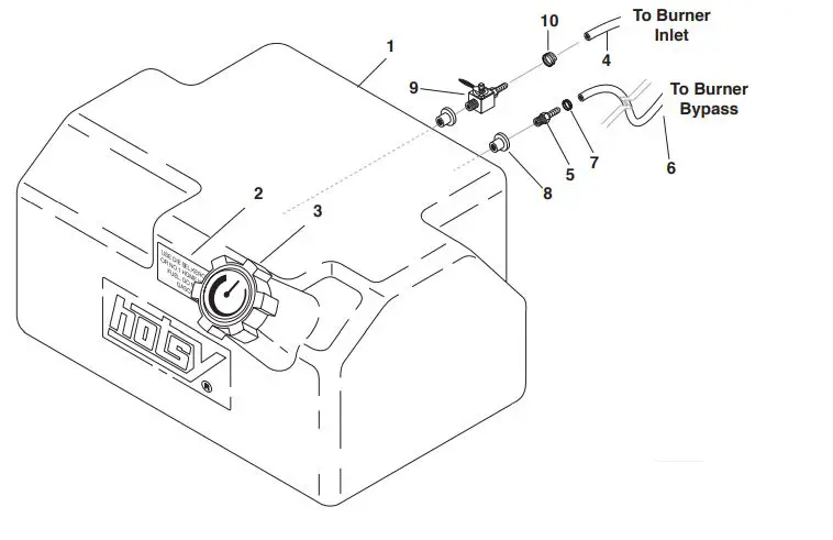
| ITEM | PART NO. | DESCRIPTION QTY |
| 1 | 8.931-594.0 | Fuel tank 8 Gal Hotsy 1 |
| 2 | 8.757-732.0 | Label, Fuel Type 1 |
| 3 | 9.803-535.0 | Cap With Fuel Display 14″ 1 |
| 4 | 9.802-254.0 | Hose 1/4″ x 20″ Push-On, 21″ Fuel Line |
| 5 | 9.802-141.0 | Hose Barb, 1/4″ Barb x 3/8″ 1 Barb, Dou |
| 6 | 9.802-254.0 | Hose, 1/4″ Push-On, Ft 15″ |
| 7 | 6.390-126.0 | Clamp, Hose, .46-.54 St 1 |
| 8 | 9.802-053.0 | Bushing, Fuel Line, Rubber 2 |
| 9 | 9.802-177.0 | Valve, 1/4″ Shut Off, 1 180 Deg |
| 10 | 8.750-933.0 | Band Hose Clamp, Hose id 1/8″- 5/16″ 1 |
CONTROL PANEL ASSEMBLY EXPLODED VIEW
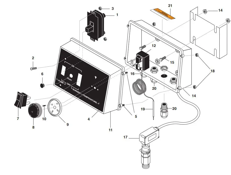
CONTROL PANEL EXPLODED VIEW PARTS LIST
| ITEM | PART NO. | DESCRIPTION | QTY | ITEM | PART NO. | DESCRIPTION | QTY | |
| 1
| 8.716-053.0 | Switch, Toggle, 40A/230V 1 | 17 | 8.716-125.0 | Switch,Pressure | 1 | ||
| 2 | 8.718-569.0 | Screw, 10-32 x 1/2″ | 2 |
| 3 | 9.804-567.0 | Nut, 10/32″ Esna | 2 |
| 4 | 8.901-142.0 | Label, Control Box | 1 |
| 5 | 9.803-249.0 | Screw, M4 x 10 | 4 |
| 6 | 8.706-741.0 | Plug, Plastic 7/16″ | 1 |
| 7 8 | 8.716-055.0 8.750-097.0 | Switch, Rocker, 10A/250V Knob, Thermostat | 1 1 | 21 | 9.800-016.0 | Label, Disconnect Power Supply | 1 |
| 9 | 8.712-190.0 | Bezel, Plastic, Thermostat | 1 | REPLACEMENT PARTS | |||
| 10 | 8.718-779.0 | Screw, 4mm x 6mm, Pan | 2 | 8.717-667.0 | O-Ring Kit | 1 | |
| 11 | 8.716-282.0 | Box Plastic Front 1 Sq Hole | 1 | 8.717-256.0 | Switch | 1 | |
| 12 | 8.750-095.0 | Thermostat, 120C/240F 2 Meter Capillary | 1 | ||||
| 13 | 9.802-480.0 | Back Box | 1 | ||||
| 14 | 9.802-775.0 | Nut, 1/4″ Flange, Zn | 4 | ||||
| 15 | 9.802-700.0 | Bolt, 1/4-20 x 3/4″ Nc Hh | 4 | ||||
| 16 | 9.802-514.0 | Strain Relief, Lt, Str, 1/2 Npt, .23-.45D | 2 | ||||
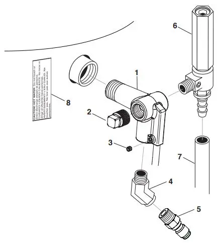
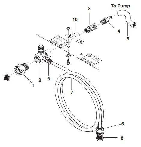
WATER INLET ASSEMBLY EXPLODED VIEW & PARTS LIST
| ITEM | PART NO. | DESCRIPTION | QTY | ||
| 1 | 9.802-147.0 | Swivel, 3/8″ Mp x 3/4″ | 1 | 3 | To Pump |
| Ghf W/ Strainer | 10 | ||||
| 2 | 9.803-275.0 | Injector, Adjustable, Inlet Hotsy | 1 4 | ||
| 3 | 8.757-191.0 | Elbow, 3/8″ Street, Brass | 1 | ||
| 4 8.706-944.0 Hose Barb, 3/8″ Barb x 3/8″ 1 Ml Pipe | |||||
| 5 | 8.711-785.0 | Hose, 3/8″ Push On, Per Ft | 8.5″ |
| 6 | 6.390-126.0 | Clamp, Hose, .46-.54 St | 2 |
| 7 | 9.802-252.0 | Hose, 1/4″ x 1/2″, Braided Vinyl /Ft | 48″ |
| 8 | 8.707-057.0 | Strainer, Plastic, 1/4″ Hose Barb | 1 |
HOSE, GUN & WAND ASSEMBLY & PARTS LIST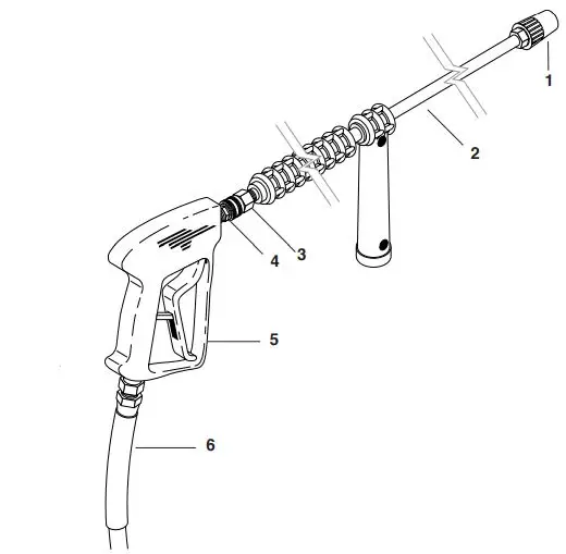
| ITEM | PART NO. | DESCRIPTION | QTY | |||
| 1 | 8.712-401.0 | Nozzle, Variable Fan | 1 | |||
| 2 | 8.725-389.0 | □ Wand, Single, 36″, Insulated W/ Side Grip | 1 | 1 | ||
| 3 | 9.802-164.0 | Coupler, 1/4″ Socket, Female, Brass | 1 | |||
| 4 | 8.707-139.0 | Coupler, 1/4″ Plug, Male Steel / Zinc | 1 | 2 | ||
| 5 | 8.751-235.0 | Gun, Hotsy, H1050, 5000 PSI, 10.4 Gpm | 1 | |||
| 6 | 8.925-130.0 | Hose, 3/8″ X 50′ 1W 4000PSI SW/SO/CPL | 1 | 4 3 | ||
| REPLACEMENT PARTS | ||||||
| ✪ | 8.717-661.0 | Grip, Handle Assy Hotsy | 1 | |||
| ✪ | 8.706-670.0 | Grip, Wand Side Handle | 1 | |||
| 8.751-119.0 | Kit, Gun Repair | 1 | ||||
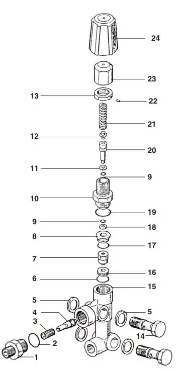
THE PUMP ASSEMBLY EXPLODED VIEW
| PUMP EXPLODED VIEW PARTS LIST | ||||
| ITEM | PART NO. | DESCRIPTION | QTY | |
| 1 | 9.802-042.0 | Elbow, 1/2 JIC X 3/8 FEM, 90DGR | 1 | |
| 2 | 8.706-944.0 | Hose Barb, 3/8″ Barb x 3/8″ ML Pipe | 1 | |
| 3 | 8.715-502.0 | Unloader, HM DX Unset (921462) | 1 | |
| 4 | 8.918-424.0 | Hose, 3/8″ x 25″, 2 Wire Pres Loop | 1 | |
| 5 | 8.707-264.0 | Plug, 3/8″ Gas Tap | 1 | |
| 6 | 8.904-909.0 | Pump, Hotsy HHC165L.1, 2.2@1450 1740 Rpm | 1 | |
| 7 | 8.706-513.0 | Mount, Vib, Neo, M8x1.25Met 5/8 St 1-1 | 1 | |
| 8 | 8.757-191.0 | Elbow, 3/8″ Street, Brass | 1 | |
| 9 | 9.803-957.0 | Oil Dipstick | 1 | |
| 10 | 8.757-184.0 | Adapter, M-BSPP X F-NPTF, 06-06 | 1 | |
| REPLACEMENT PARTS | ||||
| ✪ | 8.717-673.0 | Kit, Discharge, Unloader VBA | 1 | |
| ✪ | 8.717-672.0 | Kit, O-Ring, Unloader, VBA | 1 | |
| ✪ | 8.717-674.0 | Kit, Stem, Unloader, VBA | 1 | |
DUPLEX SERIES PUMP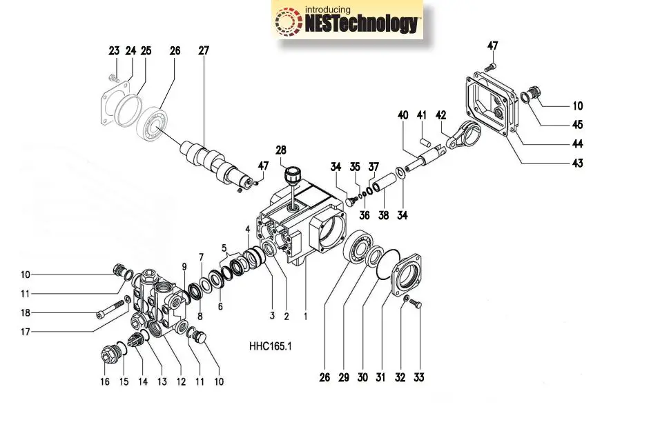
| TORQUE SPECS | |
| ITEM # | FT. LBS. |
| 16 | 75 |
| 18 | 18 |
| 23 | 7.6 |
| 34 | 7.6 |
| 35 | 4.5 |
| 47 | 7.6 |
DUPLEX SERIES PUMP
| ITEM | PART NO. | DESCRIPTION | QTY |
| 39* | See Kit Below | Spacer, Copper | 2 |
| 40 | 8.717-042.0 | Plunger Rod | 2 |
| 41 | 9.802-917.0 | Connecting Rod Pin | 2 |
| 42 | 8.717-111.0 | Connecting Rod Assy | 2 |
| 43 | 8.717-215.0 | Gasket, Crankshaft Cover | 1 |
| 44 | 8.717-136.0 | Cover, Crankcase | 1 |
| 45 | 8.707-267.0 | Gasket | 1 |
| 46 | 9.802-939.0 | Screw, Allen Crankcase | 4 |
| 47 | 9.802-945.0 | Screw, Set 6mm | 2 |
- Available in kit (See below)
| KIT NUMBERS | 8.750-001.0 | 8.725-408.0 | 8.717-584.0 | 8.717-587.0 | 8.717-670.0 |
| KIT DESCRIPTION | Seal Pack- ing 20mm, 2 Cyl HHC165 | Complete Seal Pack- ing HHC165 |
Complete Valve Assy. | Plunger Seal 2 Cyl |
Ceramic Piston |
| ITEMS NUM- BERS INLCUDED | 3, 5, 7, 8, 9 | 3, 4, 5, 6, 7, 8, 9 | 13, 14, 15 | 2 | 34, 35, 36, 37, 38, 39 |
| NO. OF CYLINDERS KIT WILL SER- VICE | 2 | 1 | 1 | 2 | 1 |
HM DX UNLOADER EXPLODED VIEW
HM DX UNLOADER EXPLODED VIEW PARTS LIST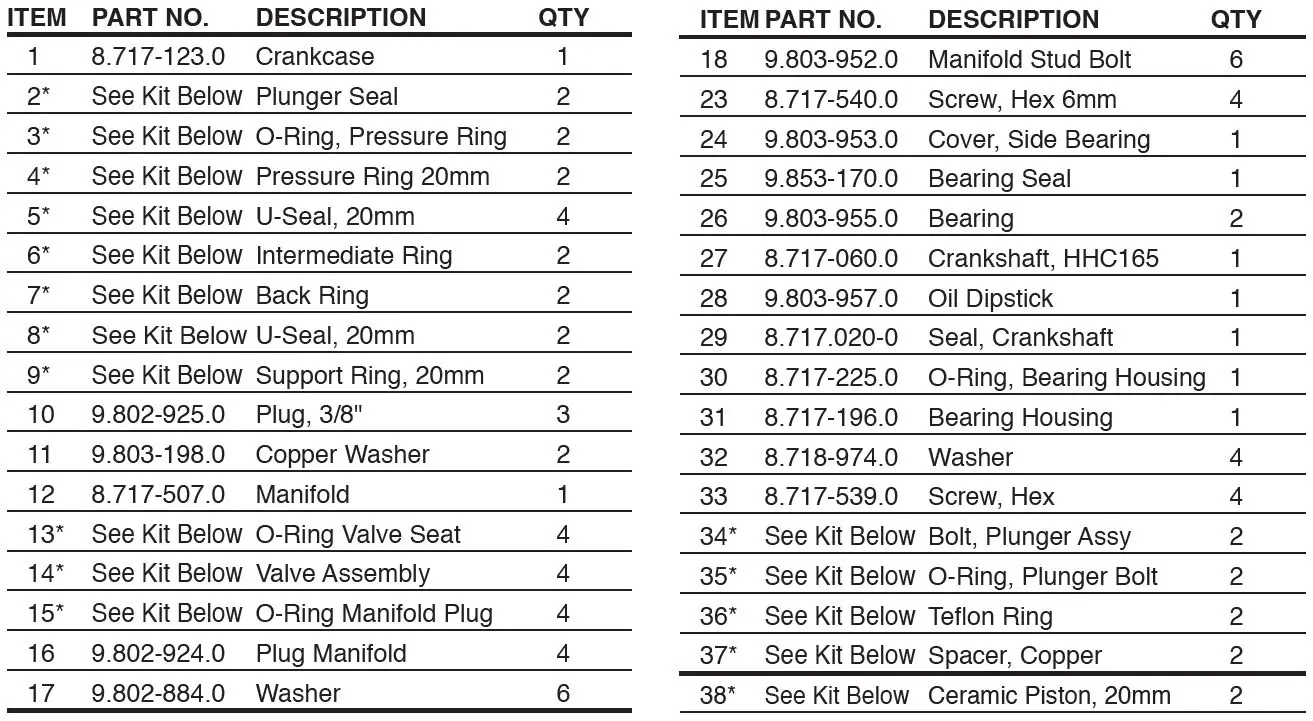
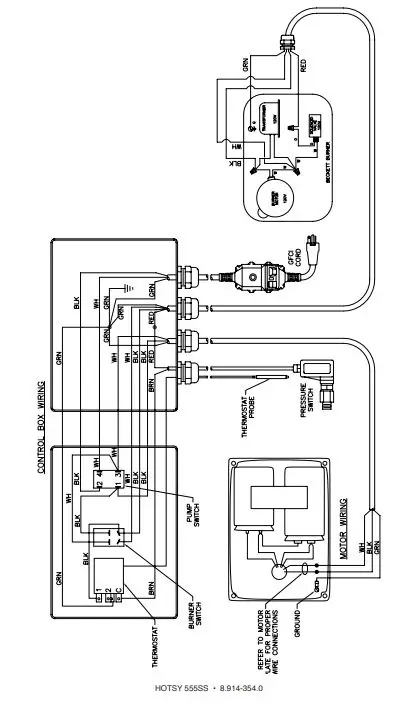
WIRING DIAGRAM
- If you need SERVICE on your pressure washer, contact your local Hotsy dealer or visit www.Hotsy.com Smartphone users scan the code below to link directly to the Service Request page.
- To REGISTER your pressure washer, please visit our Warranty Registration page at www.hotsy.com/WarrantyRegistration.aspx or scan the code below with your smartphone.

- 8.914-354.0
- Revised 08/22
- Printed in the U.S.A. by Hotsy