BE POWER EQUIPMENT HW3524HG12V Hot Water Pressure Washer
Product Information
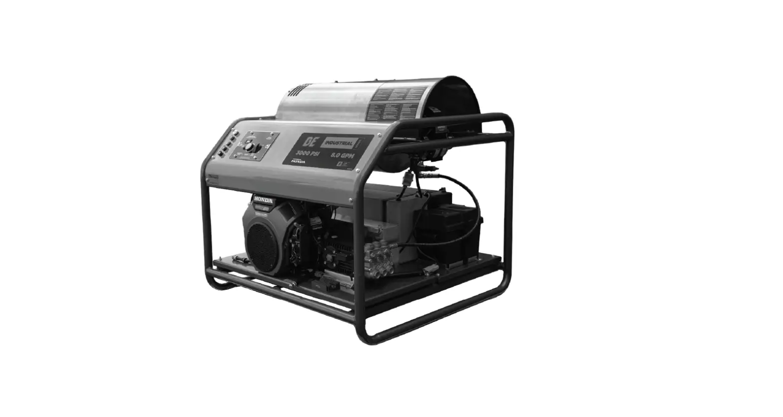
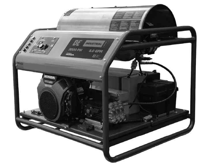
The BE Power Equipment Inc. Hot Water Pressure Washer is available in two models: HW3024HG12V and HW3524HG12V. This pressure washer is ideal for tasks requiring hot water cleaning and provides heavy-duty performance.
Product Features
- Hot water cleaning
- Heavy-duty performance
Components
- Pressure washer pump
- Hose and spray gun
- Spray tips
- Wheels for easy mobility
Product Usage Instructions
Prior to the initial use of your pressure washer, read through the complete operator’s manual. The manual should be referred to often to ensure that adequate safety and service concerns are being addressed.
Set-Up
- Connect Hose and Water Supply to Pump – Follow the instructions provided in the manual to connect the hose and water supply to the pump.
- How to Use Spray Tips – Refer to the manual for instructions on how to use spray tips.
Maintenance
It is important to perform specific maintenance as outlined in the manual. Refer to the maintenance schedule for regular maintenance intervals.
Troubleshooting
If the pressure washer is experiencing any issues, refer to the troubleshooting table in the manual for assistance.
Warranty
The pressure washer comes with a warranty. Refer to the warranty statement in the manual for details.
INTRODUCTION & PRODUCT INFO
ATTENTION: Read through the complete manual prior to the initial use of your pressure washer.
Using the Operator’s manual
The operator’s manual is an important part of your pressure washer. It should be read thoroughly before initial use, and referred to often to make sure adequate safety and service concerns are being addressed.
Reading the operator’s manual thoroughly will help avoid any personal injury or damage to your machine. By knowing how best to operate this machine, you will be better positioned to show others who may also operate the unit.
This manual was written to take you from the safety requirements to the operating functions of your machine. You can refer back to the manual at any time to help troubleshoot any specific operating functions, so store
it with the machine at all times.
Record Identification Numbers
If you need to contact an Authorized Dealer or Customer Service line (1-800-663-8331) for information on servicing, always provide the product model and identification numbers. You will need to locate the model and serial number for the pump and record the information in the spaces provided below.
| Date of Purchase: |
| Dealer Name: |
| Dealer Phone: |
| PRODUCT IDENTIFICATION NUMBERS |
| Model Number: |
| Serial Number: |
IMPORTANT SAFETY WARNINGS
This is the safety alert symbol. It is used to alert you to potential personal injury hazards. Obey all safety messages that follow this symbol to avoid possible injury or death.
| DANGER | This indicates a hazard which, if not avoided, will result serious injury or death |
| WARNING | This indicates a hazard which, if not avoided, will result in serious injury or property damage. |
| CAUTION | This indicates a hazard which, if not avoided, might result in minor or moderate injury. |
| NOTICE | This indicates a situation that could damage equipment or other property. Make sure all security messages are observed and followed. |
HAZARD SYMBOLS AND MEANINGS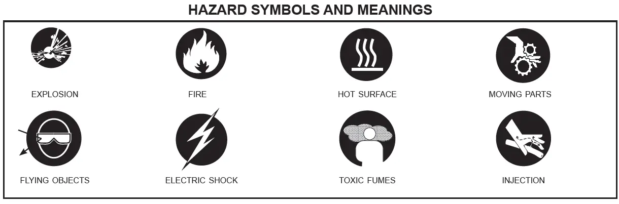
DANGER
- Always operate the pressure washer in a well-ventilated area free of flammable vapors, combustible dust, gases, or other combustible materials.
- Do not store the pressure washer near an open flame or any equipment such as a stove, furnace, water heater, etc., which utilizes a pilot light or sparking device.
- Do not use this pressure washer to spray flammable material.
- Do not smoke while filling burner fuel tank.
Never fill the fuel tanks while the pressure washer is running or hot. Allow unit to cool for two minutes. - Always refuel slowly to avoid the possibility of spilled fuel which may cause a risk of fire.
- Always leave room for fuel to expand in the gas tank. Do not overfill.
- Engine Fuel Tank: If using a Gasoline Engine, refuel with gasoline only. Do not use diesel or kerosene.
- Burner Fuel Tank (Black): When refueling the Burner Fuel Tank, use No. 1 or No. 2 fuel oil/diesel or kerosene. Do not use gasoline.
- Do not operate the unit if gasoline or diesel fuel is spilled. Wipe the pressure washer clean and move it away from the spill. Avoid creating any ignition until the gasoline or diesel fuel has evaporated.
- When the battery is being activated, hydrogen and oxygen gases in the battery are extremely explosive. Keep open sparks and flames away from the battery at all times, especially when charging.
- Be certain to disconnect the battery ground terminal before servicing. When disconnecting the cable from the battery, start with the negative terminal. When connecting them, start with the positive cable.
- When charging the battery, remove the battery vent plugs.
- Use only a voltmeter or hydrometer to check a battery charge.
- DO NOT jump start the battery unless both batteries are of equal voltage and amperage.
| WARNING | |
 | Serious injury or death may occur from a fire caused by a muffler spark. Serious injury or death may occur if system safety’s are not properly maintained. |
| • A spark arrester must be added to the muffler of this engine when using on land covered with any flammable agricultural crop (hay and grain), and if they are used in or near brush or forested areas. The arrester must be maintained in effective working order by the operator of the equipment. In the state of California, the above is required by law. (Section 4442 and 4443 of the California Public Resources Code.) Other states/provinces may have similar laws. Federal laws apply on Federal lands. • This pressure washer has a Safety Relief Valve . This should never be altered, modified, removed or made inoperative. If the device fails, replace immediately with genuine manufacturer replacement part. | |
| WARNING | |
 | Serious injury or death may occur from inhaling engine/burner exhaust or dangerous vapors. The engine exhaust from this product contains chemicals known to the State of California to cause cancer, birth defects, or other reproductive harm. |
| • Never operate this pressure washer in an enclosed area. Always ensure there is adequate ventilation (fresh outside air) for breathing and combustion. This will prevent the buildup of dangerous carbon monoxide gases. Beware of poorly ventilated areas, or areas with exhaust fans which can cause poor air exchange. This unit should only be used outdoors to ensure ventilation is never an issue. • Follow all safety instructions provided with the materials you are spraying. Use of a respirator may be required when working with some materials. Do not use this pressure washer to dispense hazardous detergents. | |
| WARNING | |
 | Serious injury or death could occur from high pressure spray penetrating the skin. |
| • Keep clear of nozzle and spray! Never put your hand, fingers or body directly over the spray nozzle. • Do not direct discharge stream at self, other persons, or pets. • This product is to be used only by trained operators. • Always keep operating area clear of other people. • Do not allow children to operate this unit or be in the vicinity while you operate it. • Seek emergency medical care if spray seems to have penetrated the skin. Do not treat as a simple cut! • High pressure hoses and fuel lines should be inspected daily for signs of wear. If evidence of failure exists, promptly replace all suspect hoses and fuel lines to prevent the possibility of injury from the high pressure spray. If a hose or fitting is leaking, do not place your hand on the leak. • Never operate the gun with the trigger held in the open position. To prevent accidental discharge, the trigger gun should be securely locked when not in use. • Before removing the spray nozzle or servicing the unit, always shut the unit off and pull the trigger of the gun to release trapped pressure (even after you shut off the unit, there is high pressure water left in the pump, hose and gun until you release it by pulling the trigger the gun). | |
| WARNING | |
 | Serious injury or death may occur from contact with electricity. |
| • Do not direct spray on or into electrical installations of any kind! This includes electrical outlets, light bulbs, fuse boxes, transformers, and the unit itself. • Do not allow metal components of the pressure washer to come in contact with live electrical components. | |
| WARNING | |
 | Serious injury may occur from touching the gasoline engine, muffler, or heat exchanger. These areas can remain hot for some time after the pressure washer is shutdown. |
| • Never allow any part of your body to contact the gasoline engine, muffler, or heat exchanger. | |
| WARNING | |
 | Serious injury may occur from a pressure washer malfunction or exploding accessories if incorrect system components, attachments, or accessories are used. Serious injury or death may occur if attempting to start the pressure washer when the pumping system is frozen. |
| • Never make adjustments to the factory set pressures. • Never exceed the manufacturer’s maximum allowable pressure rating of attachments. • Do not allow any hoses to make contact with the heat exchanger to prevent the possibility of bursting. Avoid dragging the hoses over abrasive surfaces such as cement. • Use only manufacturer-recommended repair parts for your pressure washer. • In freezing temperatures, the unit must always be warm enough to ensure there is no ice formation in the pump. Do not start the pressure washer if it has been transported in an open or under-heated vehicle without first allowing the pump to thaw. | |
| WARNING | |
 | Serious injury may occur to the operator from moving parts on the pressure washer. |
| • Before making any adjustments, be certain the engine is turned off and the ignition cable(s) is removed from the spark plug(s). Turning the machinery over by hand during adjustment or cleaning might start the engine and machinery with it. • Do not operate the unit without all protective covers in place. | |
| WARNING | |

| Serious injury or death may occur from detergents contacting the skin. Serious injury can occur from loose debris being propelled at a high speed from the spray gun. Injury may occur if the operator loses their balance caused by the thrust of water traveling through the spray nozzle. |
| • Never use any solvents or highly corrosive detergents or acid type cleaners with this pressure washer. • Protective equipment such as rubber gloves and respirators are advisable, especially when using cleaning detergents. • Keep all detergents out of the reach of children! • Always wear protective goggles when operating the unit to shield the eyes from flying debris and detergents. • Do not direct spray toward fragile materials such as glass. • Stay alert: watch what you are doing. Do not operate the unit when fatigued or under the influence of alcohol or drugs. • Never squeeze the trigger unless securely braced. • Do not overreach or stand on unstable support. • Wet surfaces can be slippery. Wear protective foot gear and keep good footing/balance at all times. • Never pull the trigger of the gun while on a ladder, roof, or another unstable surface. • Always hold on firmly to the gun/lance assembly when starting and operating the unit. Failure to do so can cause the lance to fall and whip dangerously. • Do not leave the pressurized unit unattended. Shut off the pressure washer and release trapped pressure before leaving. • Do not operate the unit if you see any fuel, oil, or water leaking from the machine. DO NOT resume operation until the unit has been inspected and repaired by a qualified technician. • Do not transport the unit by pulling on hoses or cords. | |
GENERAL INFORMATION
PRODUCT FEATURES & COMPONENTS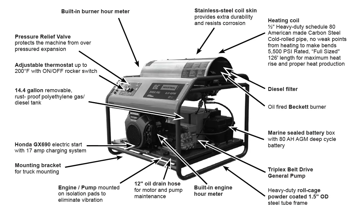
| Description | HW3024HG12V | HW3524HG12V |
| Pressure Rating | 3000 | 3500 |
| GPM | 8 | 5.6 |
| Engine Model | HONDA GX690 | HONDA GX690 |
| Displacement | 688 CC | 688 CC |
| Voltage | 12VDC | 12VDC |
| Amps | 17 | |
| Burner Type | ADC Beckett | |
| Unloader | VRT100 | VRT3 |
| Pump Type | GP TSF2021 | GP TS2021 |
| Nozzles Included | 0°, 15°, 25°, 40°, Soaper | |
| Hose length | 50’ | |
| Start Type | Electric Start | |
| Gasoline Capacity | 54.5 litres (14.4 U.S. gal) | |
| Diesel Capacity | 54.5 litres (14.4 U.S. gal) | |
| Engine Oil Capacity | 2.0 litres (2.1 U.S. qts) | |
| Weight | 444 kg (979 lbs) | |
| Hose diameter | 3/8″ | |
| Hose Material | Rubber / Double Wire Braid | |
SET-UP
WATER SUPPLY
- Select a water supply hose which is a quality grade of the hose measuring at least 3/4″ ID and no longer than 50 feet to the water tank.
- Attach a hose measuring 1/2″ ID and rated for 100PSI minimum to the bypass from the unloader valve to the water supply tank
- Connect the hose to the inlet of your high pressure pump. Ensure the connection is tight at both ends (at the pump inlet and at the water supply source).
- Install water inlet filter between pump and tank.
- Never allow the unit to operate without the water hose attached and the water supply opened all the way.
NOTICE
If there is a high mineral content in your water, it is highly recommended that a water softener and an additional water strainer be added to the water inlet. This will help prevent the possibility of excessive scale buildup inside the heat exchanger coil.
Pumps are water-cooled. When the machine is running, ensure the trigger of the gun is pressed to allow a constant flow of fresh water into and out of the pump. Do not let the machine run for more than 30 seconds without pulling the trigger.
Most pumps are protected by a thermal valve (1). The thermal valve releases water if a pump starts to run too hot. It will prevent catastrophic heat failure. However, the pump may have suffered damage and need maintenance, repair, or replacement. If it does not reset and continues to leak water, the thermal valve may need to be replaced.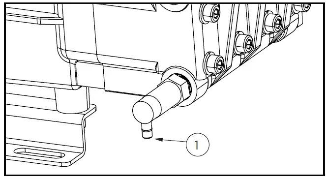
HOW TO USE SPRAY TIPS
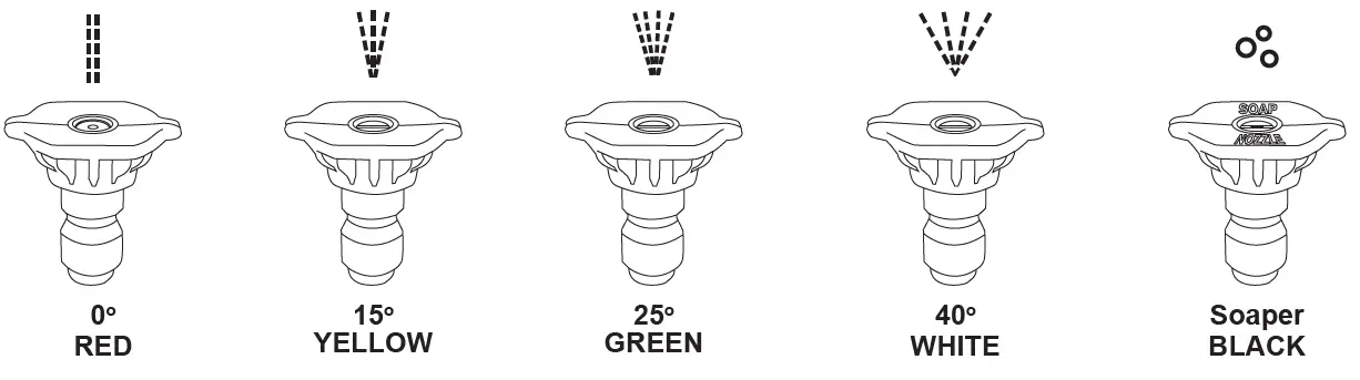
The quick–connect on the nozzle extension allows you to switch between five different quick-connect spray tips. Spray tips can be changed while the pressure washer is running once the spray gun trigger safety lock is engaged. The spray tips vary the spray pattern as shown above.
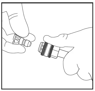
FOLLOW THESE INSTRUCTIONS TO CHANGE SPRAY TIPS:
- Pull back collar on quick–connect coupler and pull the current spray tip off. Store the spray tips in the holder provided on the handle. Storing tips in the designated holder will help prevent any debris from clogging the tip.

- Select the desired spray tip:
- For a gentle rinse, select the white 40° spray tip.
- For light cleaning, select the green 25° spray tip.
- For high pressure cleaning, select the yellow 15° spray tip.
- To scour the surface, select the red 0° spray tip.
- To apply detergent, select the black spray tip. No other spray tip will draw soap
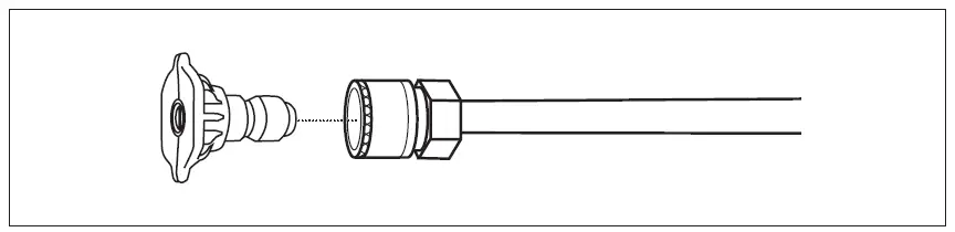
- Pull back on collar, insert spray tip and release collar. Tug on spray tip to ensure it is securely in place.
USAGE TIPS
- For most effective cleaning, keep spray tip 8 to 24 inches away from cleaning surface.
- If the spray tip gets too close to the surface being cleaned, especially using a high pressure spray tip (red or yellow), it may be damaged. Do not use the red spray tip on glass. Doing so could result in broken or cracked glass.
OPERATION
PRE-OPERATION SAFETY
- This unit should only be placed on a level surface to ensure proper lubrication for the water pump while operating. Placing the unit on a level surface will also ensure that fuel, oil, and other fluids don’t spill during operation. NEVER spray water directly on the unit.
- Do not use unit in an area:
- with insufficient ventilation.
- where there is evidence of oil or fuel leaks.
- where flammable gas vapors may be present.
This unit has multiple ignition sources that could cause a fire or explosion.
- Do not allow the unit to be exposed to rain, snow, or freezing temperatures. If any part of the unit becomes frozen, excessive pressure may build up in the unit which could cause it to burst. This would result in possible serious injury to the operator or bystanders.
- Pump oil level should be checked before each use. Make certain the oil is on the “Full” mark on the dipstick or in the center of the oil sight glass. If the level appears to be low, fill with SAE30W non-detergent pump oil.
- Your pressure washer is equipped with an electric starter. On initial start-up, wear proper eye and skin protection when filling the battery with acid. Fully charge the battery to allow electric starter to function.
MANUAL & SAFETY REVIEW
- Review “Risk of Explosion or Fire” warnings, before fueling.
- Locate the Safety Decals on your unit and heed their warnings.
- Engines: See the included engine Owner’s Manual for fuel requirements.
- Burner Fuel: When filling tank, use No. 1 or No 2 fuel oil/diesel or kerosene.
- Check the engine oil level before starting the engine.
- Review the engine manual accompanying this pressure washer for correct engine start-up and maintenance procedures.
START-UP PROCEDURE PREPARATION
Before starting the unit, perform the following procedures:
- Check the oil level and condition for the pump and engine. We recommend SAE 10W30 oil for engines and SAE 30 mineral oil for pumps.
- Inspect the water inlet strainer. Clean or replace if necessary.
- Check all hose connections to ensure they are securely tightened.
- Inspect for system water leaks, oil leaks and fuel leaks. If a fuel leak is found, do not start the unit. Be sure that all damaged parts are replaced and mechanical problems are corrected prior to operation of the unit.
- Inspect high pressure hoses for kinking, cuts, and leaks. If a cut or leak is found, do not use the hose. Replace hose before starting unit. Be sure that all damaged parts are replaced and that the mechanical problems are corrected prior to operation of the unit.
START-UP (COLD WATER)
To start your pressure washer for the first time, follow these instructions step-by-step. This starting information also applies if you have let the pressure washer sit idle for at least a day.
- Make sure the unit is level and placed on solid surface.
- Connect garden hose to water inlet on pressure washer pump. To do this, thread the end of the hose into the inlet by hand until tight and secure.
- Attach wand extension to spray gun. Tighten by hand.
NOTICE
DO NOT run the pump without the water supply connected and turned on. Failure to follow this rule will result in damage to the pump. Damage caused by running the pump without water is not covered by warranty. - Choose desired spray tip, pull back nozzle extension collar, insert spray tip and release collar. Tug on spray tip to make sure it is securely in place. See Spray Tips on page 9 for more information.

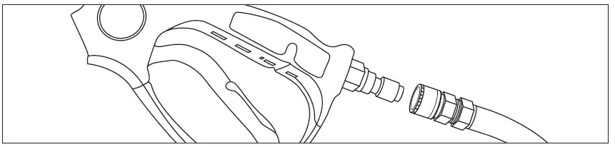
- Pull down on the collar of the quick-connect coupler, slide onto the gun connector and let go of collar. Pull on hose to ensure the connection is tight.

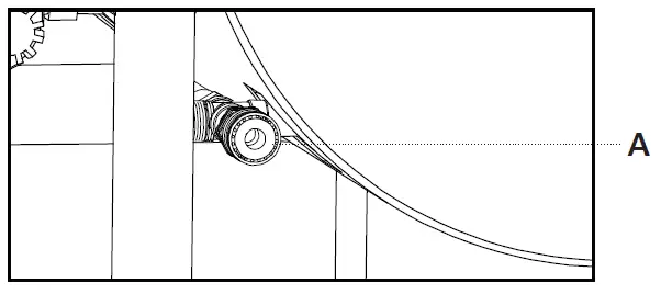
- Attach the other end of the high pressure hose to high pressure outlet (“A” on diagram below) on pump. Pull down on collar of quick-connect, slide onto pump and let go of collar. Note that some pumps require the hose to be threaded on. Tug on the hose to ensure connection is secure.

- Turn water supply on if you have not already done so. Point the gun in a safe direction and squeeze the trigger to purge the pump of air and debris. Do this until water flow is flowing at a steady rate. Continue to hold trigger of gun down while starting the machine to ensure there is no pressure build-up.
- Take a final look at all connections to make sure there are no leaks or loose connections. If there are any leaks in hoses, they must be replaced.
IMPORTANT: DO NOT siphon standing water for the water supply. Make sure burner switch is OFF - To start the machine, locate the electric ignition switch on the right side of the engine. Insert the key and turn it to the “ON” position” until the unit starts. Do not hold the switch to the “ON” position for more than 5 seconds as this can cause damage to the engine. Check to ensure fuel valve is in the ON position and if starting cold, move the choke lever to the “CLOSED” position. Reference the component diagram below for the location of these parts.
Remember to gradually move the choke lever back to the “open” position once the engine is running. 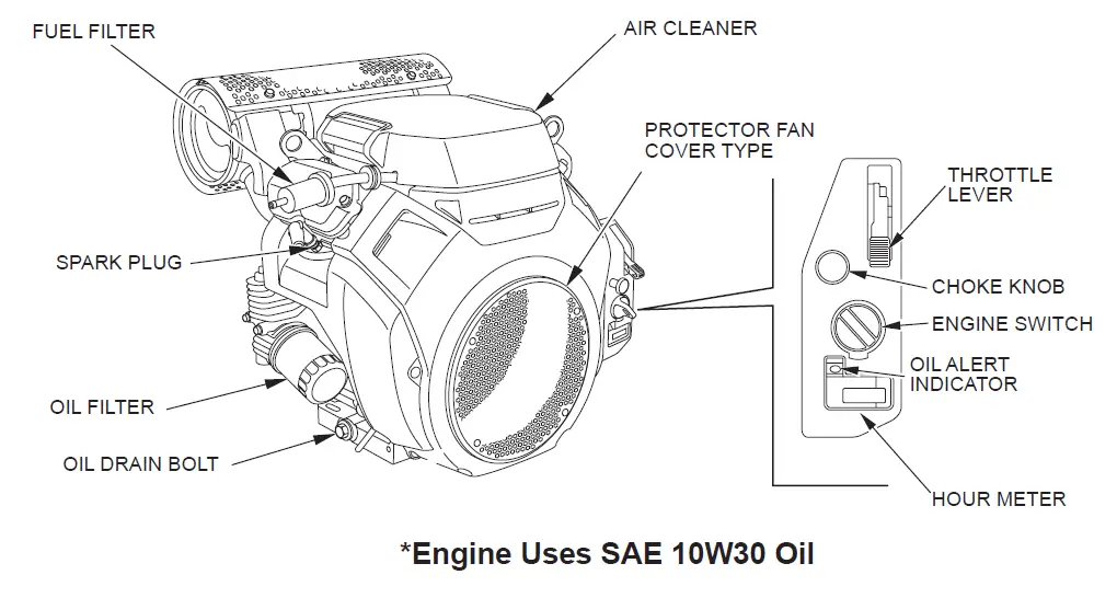
HOT WATER OPERATION
Now that the unit is running, it is operating as a cold water pressure washer.
When you wish to switch to hot water, turn the burner switch to the “ON” position.
NOTICE: Upon initial start-up, water will begin heating up in approximately 20 seconds. It will reach maximum temperature within 2-1/2 minutes providing that the trigger is continuously pressed down. The burner will not fire when the trigger is released.
WARNING: The temperature of the water can become extremely hot during operation. Use caution when operating the spray gun.
APPLYING DETERGENT
NOTICE: This feature is designed for use with mild detergents only. Since the cleaning solution travels through the heat exchanger coil, DO NOT use corrosives as they will cause extensive damage as well as pose a considerable safety hazard.
- Prepare detergent solution according to label directions. Never pump acids, alkaline, abrasive fluids or solvents through the unit. Due to the unknown and often corrosive characteristics of many detergents commonly used in the pressure washer cleaning industry, it is recommended to use only mild detergents with this unit.
- Fully immerse the detergent strainer into the detergent solution.
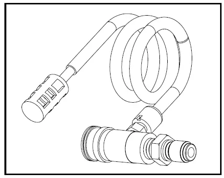
- To apply solution, install the black soap nozzle to the tip of the spray gun, unlock the gun, and squeeze the trigger. After a few moments, a detergent/water mixture will exit the nozzle. Start spraying the lower portion of the surface being cleaned and move up, using long overlapping strokes. Applying from the bottom up helps avoid streaking. Allow everything to soak briefly.
- Avoid working on hot surfaces or in direct sunlight to minimize the chances of the detergent drying, which may result in damaged surfaces. Be certain to rinse a small section at a time.
- To rinse, lock the trigger gun in the “OFF” position. From here, securely place the white or green spray tip in the end of the spray gun. Unlock the trigger and spray. It will take about 30 seconds to purge all detergent from the line. For best rinsing results, start at the top and work down.
- Siphon a gallon of water through the low-pressure detergent injection system after each use. This prevents the possibility of corrosion or detergent residue causing mechanical problems during the next use.

SHUTTING THE UNIT DOWN
- Move the burner switch to the “OFF” position.
- Squeeze the trigger and discharge the water for three minutes to cool the heat exchanger and high pressure hose. Insufficient cool-down periods for the high pressure hose will cause excessive wear and eventual rupture of the hose.
- Do not close the choke to stop the engine. Backfire or engine damage may occur.
- Move the engine key switch to the OFF position.
- Turn off the water supply and pull the trigger of the gun to relieve trapped pressure.
Disconnect and drain the high pressure hose, gun, and lance. Wipe the unit clean and store in a non-
freezing environment.
STORAGE AND WINTERIZING
If you do not plan to use the pressure washer for more than 30 days, you must prepare the engine and pump for long term storage. See the engine user manual for specific instructions regarding this.
When storing the unit for winter, it is important to ensure it is stored in the right environment. Ensure the storage area stays above freezing during cold weather, and try to limit the amount of dust gathered on the unit via a cover.
| WARNING | |
| Storage covers can be flammable. |
| • DO NOT place a storage cover over a hot pressure washer. • Let equipment cool for at least 30 minutes before placing the cover on the equipment. | |
You will need to ensure that the fuel is drained from the engine prior to storage. For the steps required to do this, see the engine user manual.
Once the unit has been stored and the gasoline has been drained, the last thing to do is to winterize your pump. This can be done in one of two ways:
- BE “Pump Saver” Solution (P/N: 85.490.046). This is an anti-freeze solution that is used before storing the unit. It coats to inside of the pump to ensure that any residual water doesn’t freeze. To use BE Pump Saver, follow the instructions written on the bottle. Water freezing in the pump will damage seals and other internal parts. Freezing damage is not covered by warranty.
| CAUTION |
| Be certain the hoses and spray gun are not attached to the pump during application of pump saver or use of the blowout tool. Having a hose attached greatly reduces the amount of water/debris removed from the pump and coil. |
| NOTICE |
| You must protect your unit from freezing temperatures. |
| 1. Failure to do so will permanently damage your pump and render your unit inoperable. 2. Freezing damage is not covered under warranty. |
MAINTENANCE
SPECIFIC MAINTENANCE
ENGINE: The engine instructions that accompany your unit detail specific procedures for the maintenance of the engine. Following the engine manufacturer’s recommendations will extend the engine’s life and ensure
the best possible performance.
PUMP: Change the pump oil after the first 50 hours of operation. After the initial change, every 3 months or 250-hour intervals are recommended. If oil appears dirty or milky, changes may be required in greater frequency. Use SAE 30 non-detergent pump oil and fill only to the center of the oil sight glass. DO NOT overfill.
NOZZLE: Water flow through the spray nozzle will erode the orifice over time, making it larger. This will result in a reduction of pressure. Nozzles should be replaced whenever pressure is less than 85% of the maximum. The frequency of replacement will depend upon such variables as mineral content in the water and number of hours the nozzle is used. Every 3-6 months tends to be a standard interval for replacement.
MAINTENANCE
MAINTENANCE SCHEDULE
| PROCEDURE | DAILY | 3 MONTHS | 6 MONTHS | 9 MONTHS | 12 MONTHS | |
| Check engine oil level | X | |||||
| Change engine oil | ***** | X | X | X | X | |
| Check water pump oil level | X | |||||
| Change water pump oil | ** | X | X | X | X | |
| Oil leak inspection | X | |||||
| Fuel leak inspection | X | |||||
| Water leak inspection | X | |||||
| Hose inspection | X | |||||
| Water inlet screen inspection | X | |||||
| Check fuel filter | X | X | X | X | ||
| Replace fuel filter | X | |||||
| Inspect belts | X | X | X | X | ||
| Replace high pressure nozzle | *** | X | X | X | X | |
| Inspect fuel pump filter | * | X | ||||
| Replace fuel nozzle | * | X | ||||
| Check burner air adjustment | X | X | X | X | ||
| Check burner electrodes | * | X | ||||
| Test water pressure | * | X | X | X | X | |
| Test fuel pressure | * | X | X | X | X | |
| Test water temperature | * | X | X | X | X | |
| Descale coil | **** | X |
* Must be performed by an authorized service technician.
** The pump oil must be changed after the first 50 hours of operation and then every 250 hours or 3 months, whichever comes first.
*** High-pressure nozzle should be replaced whenever pressure drops to less than 85%.
**** Scale build-up will vary with mineral content in the water and amount of usage. Descaling can range from weekly to yearly maintenance.
***** The engine oil must be changed after the first 8 hours of operation and then every 50 hours or 3 months, whichever comes first.
UNIT BREAKDOWN
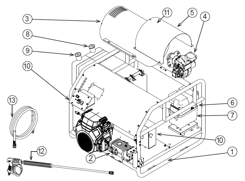
| ITEM #. | PART # | DESCRIPTION | QTY. | PART # | DESCRIPTION | QTY. |
| 1 | 85.600.220 | FRAME ASSEMBLY | 1 | AL607 | UNLOADER, VRT3, 5.6GPM (3524HG12V) | 1 |
| 2 | 85.130.071B | GENERAL PUMP TSF2021 8GPM (3024HG12V) | 1 | 85.300.033 | UNLOADER, VRT100, 8.0GPM (3024HG12V) | 1 |
| 85.130.026B | GENERAL PUMP TS2021 5.6GPM (3524HG12V) | 1 | 85.300.082 | PRESSURE SWITCH | 1 | |
| 3 | 59.000.200 | COIL, HOT WASH 5.6GPM (3524HG12V) | 1 | 85.300.088 | EXPANSION VALVE | 1 |
| 59.000.208 | COIL, HOT WASH 8GPM (3024HG12V) | 1 | 47.002.045 | BELTS 3VX450 | 4 | |
| 4 | 59.110.016 | BURNER / (12V ADC SERIES) | 1 | 59.000.104 | FUEL FILTER | 2 |
| 5 | 59.000.201 | BURNER HOOD; HOT WASH | 1 | 85.550.063 | ENGINE AIR FILTER | 1 |
| 6 | 85.603.101 | BATTERY BOX FOR SKID HW | 1 | 85.550.064 | ENGINE OIL FILTER | 1 |
| 7 | 85.603.100 | BATTERY, AGM, 12V, 80AH | 1 | 85.550.065 | ENGINE DIP STICK | 1 |
| 8 | 85.601.040 | 14.4 GALLONS DIESEL FUEL TANK | 1 | 85.550.066 | ENGINE SPARK PLUG | 2 |
| 9 | 85.601.041 | 14.4 GASOLINE FUEL TANK | 1 | 85.550.008L | MUFFLER | 1 |
| 10 | 85.602.222 | BELT GUARD | 1 | |||
| 11 | 59.000.008 | INSULATION | 1 | |||
| 12 | 85.205.066H | GUN | 1 | |||
| 13 | 85.238.251 | HOSE | 1 | |||
CONTROL PANEL BOX
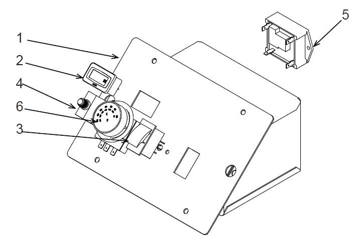
| ITEM NO. | PART NUMBER | DESCRIPTION | QTY. |
| 1 | 85.600.231 | BURNER CONTROL BOX | 1 |
| 2 | 59.000.206 | HOUR METER | 1 |
| 3 | 59.000.103 | TOGGLE ON/OFF SWITCH FOR 12V BURNER (ADC SERIES) | 1 |
| 3 | 59.000.205 | TOGGLE ON/OFF SWITCH FOR 120V BURNER (AFG SERIES) | 1 |
| 4 | 85.504.026 | PUSH TO RESET 25A CIRCUIT BREAKER (12V) | 1 |
| 5 | 59.000.102 | LOW VOLTAGE RELAY (12V) | 1 |
| 6 | 85.400.071 | THERMOSTAT | 1 |
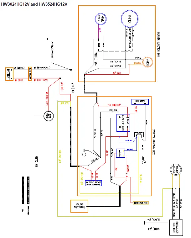
CONTROL PANEL WIRE DIAGRAM
BURNER BREAKDOWN AND PARTS LIST
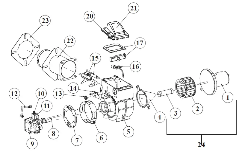
| Illustration # | Description |
| 1 | DC Motor |
| 2 | Blower Wheel |
| 3 | Coupling |
| 4 | Air Guide |
| 5 | Burner Housing – Black |
| 6 | Air Band |
| 7 | Air Shutter – 4 Slot Air Shutter – 8 Slot |
| 8 | Cord set |
| 9 | Pump (CleanCut) |
| 10 | Valve Stem |
| 11 | 12 Volt Coil |
| 12 | 8″ Copper Tubing |
| 13 | Escutcheon Plate Spline Nut |
| 14 | Escutcheon Plate |
| 15 | Electrode Kit over 3-5/8″ |
| 16 | Cad Cell Detector |
| 17 | Igniter Gasket Kit |
| Illustration # | Description |
| 20 | Igniter Assy with baseplate |
| 21 | Igniter only |
| 22 | Air Tube Ass’y |
| 23 | Flange Mounting Gasket |
| 24 | Motor Kit with Blower Wheel and Coupling |
| Not Shown | Tune-up Kit for 30 & 35 Air Tube Lengths |
| Illustration # | PART # | Description |
| 9 | 59.110.000 | Fuel Pump |
| 8,10,11 | 59.110.001 | Fuel Solenoid |
| 15 | 59.110.002 | Electrode Assy |
| 21 | 59.110.003 | Igniter |
| 1 | 59.110.004 | Blower Motor |
| 3 | 59.110.005 | Shaft Coupling |
PUMP BREAKDOWN AND PARTS LIST
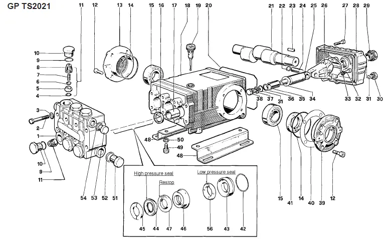
PARTS LIST
| ITEM PART NO. DESCRIPTION KIT NO. QTY. ITEM PART NO. DESCRIPTION KIT NO. QTY. ITEM PART NO. DESCRIPTION KIT NO. QTY. | |||||||||||
| 1 47120841 Manifold | 1 | 19 98210600 Oil Dip Stick | 1 | 37 96728000 Washer | 6 | 3 | |||||
| 47120941 Manifold, Nickel-Plated | (TS2021-N) | 20 90392200 O-Ring, Cover | 1 | 38 47219566 Screw, Plunger | 6 | 3 | |||||
| 2 99320600 Screw, M8 x 70 | 8 | 21 47021735 Crankshaft | 1 | 39 47150022 Cover, Crankcase | 1 | ||||||
| 3 96702000 Washer, M8.4 8 22 90055700 Ring, Snap 6 40 97567800 Shim 2 | |||||||||||
| 4 90384100 O-Ring, .674 x .103 | 1 | 6 | 23 91489000 Key | 1 | 41 | 90164800 Seal, Oil | 3 1 | ||||
| 5 36200366 Seat, Valve | 1 | 6 | 24 97738000 Pin, Wrist | 3 | 42 | 90361600 O-Ring, 1.364 x .070 | 10, 28 3 | ||||
| 6 36200176 Plate, Valve | 1 | 6 | 25 47050554 Guide, Plunger | 3 | 43 | 47080570 Retainer, Packing | 10, 28 3 | ||||
| 7 94737600 Spring 1 6 26 47030001 Rod, Connecting 3 44 90270500 Packing 28, 69 3 | |||||||||||
| 8 36200251 Guide, Valve | 1 | 6 | 27 | 99191200 | Screw, M6 x 30 | 5 | 45 47100051 Ring, Head, M20 | 7, 28 | 3 | ||
| 9 90384700 O-Ring, .797 x .103 | 4, 5 | 6 | 99183700 | Screw, M6 x 14 (T1011) | 5 | 46 47216970 Intermed. Ring | 28, 71 | 3 | |||
| 10 98222000 Cap | 4 | 6 | 28 | 47160122 | Cover, Crankcase | 1 | 47 90270400 Restop Ring | 28, 69, 71 | 3 | ||
| 98222200 Cap, Ni-Plated (TS2021-N) 5 47160022 Cover, Crankcase (T1011) 48 47200074 Pump Feet 2 | |||||||||||
| 11 36703201 Valve Assembly | 1 | 6 | 29 97596800 Oil Indicator | 1 | 49 99364400 Screw, M10 x 18 | 4 | |||||
| 12 99303900 Screw, M8 x 16 | 8 | 30 98204100 Cap | 1 | 50 96710600 Washer, M10.2 | 4 | ||||||
| 13 47150122 Cover, Crankcase | 1 | 31 90358500 O-Ring, .426 x .070 6 | 4 | 51 98217600 Cap | 1 | ||||||
| 14 90391300 O-Ring, 2.675 x .103 2 32 99309900 Screw, M8 x 35 6 52 96751400 Washer, M21.5 1 | |||||||||||
| 15 640047 Bearing, Roller | 2 | 33 96701400 Washer, M8.4 | 6 | 53 98210000 Cap | 1 | ||||||
| 16 90162500 Seal, Oil | 2 | 3 | 34 96728600 Washer, M14 | 6 | 3 | 54 96738000 Washer, M17.5 | 1 | ||||
| 17 90912600 Bushing | 3 | 35 47040409 Plunger, (20 mm) | 3 | 56 90271000 Seal, Low Press., 20mm 28,69 3 | |||||||
| 18 47010522 Crankcase 1 36 90506700 Ring, Back-up 6 3 | |||||||||||
REPAIR KITS
| KIT NO. | 1 | 2 | 3 | 4 | 5 | 6 | 7 | 10 | 28 | 69 | 71 |
| ITEM NO.s INCLUDED IN KIT | 4, 5 6, 7, 8 (11) | 16 | 41 | 9, 10 | 9, 10 | 31, 34, 36, 37, 38 | 45 | 42, 43 | 42, 43, 44, 45, 46, 47, 56 | 44, 47, 56 | 46, 47 |
| NUMBER OF ASSEMBLIES IN KIT | 6 | 3 | 2 | 6 | 6 | 3 | 6 | 3 | 1 | 3 | 3 |
| NUMBER OF CYLINDERS KIT WILL SERVICE | 3 | 3 | – | 3 | 3 | 3 | 3 | 3 | 1 | 3 | 3 |
TORQUE SPECS*
| Position | Ft.-lbs. |
| 2 | 22.1 |
| 10 | 73.7 |
| 12 | 14.7 |
| 27 | 7.3 |
| 29 | 13.2 |
| 30 | 14.7 |
| 32 | 14.7 |
| 38 | 14.7 |
| 49 | 29.4 |
| 51 | 29.4 |
| 53 | 29.4 |
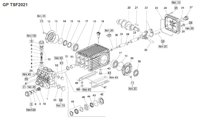
PARTS LIST
| POS. PART NO. DESCRIPTION QTY. POS. PART NO. DESCRIPTION QTY. POS. PART NO. DESCRIPTION QTY. 1 66124541 Manifold, Ø 18mm 1 22 66030001 Connecting Rod, Complete 3 43 90361600 O-ring, Ø 34.65×1.78 3 | |||||||||||||||||||||||||
| 66120041 | Manifold, Ø 20mm | 1 | 23 | 90392200 O-ring, Ø133.02×2.62 | 1 | 44 | 90265200 LP Seal, Ø 18mm 3 | ||||||||||||||||||
| 66120141 | Manifold, Ø 22 mm | 1 | 24 | 66160022 Rear Cover | 1 | 90269000 LP Seal, Ø 20mm 3 | |||||||||||||||||||
| 66120241 | Manifold, Ø 24mm | 1 | 25 | 99188400 Screw, M6x20 | 4 | 90271500 LP Seal, Ø 22mm 3 | |||||||||||||||||||
| 66124641 Manifold, Ø 28mm 1 26 90405100 O-ring, 26.58×3.53 1 90273800 LP Seal, Ø 24mm 3 2 99380100 Headbolt M10 x 90 8 27 63210051 Oil Level Indicator 1 90275300 LP Seal, Ø 28mm 3 | |||||||||||||||||||||||||
| 3 | 90385700 O-ring, Ø 23.81×2.62 | 12 | 28 | 98204100 Plug, G1/4”x9 | 1 | 45 | 66216370 Intermediate Ring, Ø 18mm 3 | ||||||||||||||||||
| 4 | 36203366 Valve Seat | 6 | 29 | 701013 O-ring, Ø .426x.070 | 4 | 66216070 Intermediate Ring, Ø 20mm 3 | |||||||||||||||||||
| 5 | 36203476 Valve Poppet | 6 | 30 | 99309900 Screw, M8x35 | 6 | 66216170 Intermediate Ring, Ø 22mm 3 | |||||||||||||||||||
| 6 94738800 Valve Spring Ø10x18x18.5 6 32 97740500 Wrist Pin, 14×39 3 66216470 Intermediate Ring, Ø 24mm 3 | |||||||||||||||||||||||||
| 7 | 36203551 Valve Guide | 6 | 33 | 66050064 Piston Guide | 3 | 66220070 Intermediate Ring, Ø 28mm 3 | |||||||||||||||||||
| 8 | 90516500 Anti-ext ring Ø24.7x29x1.5 | 6 | 34 | 96710100 Flinger Washer | 3 | 46 | 90265500 HP Seal, Ø 18mm 3 | ||||||||||||||||||
| 9 | 66130041 Plug, M32x1.5×29.5 | 6 | 35 | 66040309 Plunger, Ø 18mm | 3 | 90269200 HP Seal, Ø 20mm 3 | |||||||||||||||||||
| 10 | 36712701 Valve Assy., Complete | 6 | 66040009 Plunger, Ø 20mm | 3 | 90271700 HP Seal, Ø 22mm 3 | ||||||||||||||||||||
| 11 99303900 Screw M8 x 16 8 66040109 Plunger, Ø 22 mm 3 90274100 HP Seal, Ø 24mm 3 | |||||||||||||||||||||||||
| 12 | 47151222 | Cover | 1 | 66040409 | Plunger, Ø 24mm | 3 | 90275400 | HP Seal, Ø 28mm | 3 | ||||||||||||||||
| 13 | 90391300 | O-ring, Ø67.95×2.62 | 2 | 66041009 | Plunger, Ø 28mm | 3 | 47 | 47200074 | Pump Rail | 2 | |||||||||||||||
| 14 | 90387700 | O-ring, Ø 39.34×2.62 | 1 | 36 | 90358400 | O-ring, Ø 10.82×1.78 | 3 | 48 | 96710600 | Washer M10 | 4 | ||||||||||||||
| 15 | 70211801 | Oil Sight Glass | 1 | 37 | 66219566 | Plunger Bolt | 3 | 49 | 99364400 | Screw M10 x 18 | 4 | ||||||||||||||
| 16 | 90075600 | Retainer Clip | 1 | 38 | 47151022 | Side Cover, PTO | 1 | 50 | 90912600 | Guide Bushing | 3 | ||||||||||||||
| 17 | 91838000 | Bearing | 2 | 39 | 90164800 | Seal, Shaft | 1 | 51 | 90162500 | Seal, Plunger Rod | 3 | ||||||||||||||
| 18 | 66010022 | Crankcase | 1 | 40 | 90383300 | O-ring, Ø 13.95×2.62 | 1 | 52 | 96738000 | Gasket, Aluminum 3/8″ | 1 | ||||||||||||||
| 19 | 98210600 | Dipstick, vented | 1 | 41 | 98210000 | Plug 3/8 x 13 | 2 | 53 | 96770000 | Washer | 1 | ||||||||||||||
| 20 | 66021035 | Crankshaft, 19mm Stroke, | 1 | 42 | 66080370 | Seal Retainer, Ø 18mm | 3 | 54 | 98226800 | Plug, G3/4”x16 | 1 | ||||||||||||||
| Dual Shaft | 66080070 | Seal Retainer, Ø 20mm | 3 | 55 | 98204300 | Plug 1/4″ x 13 | 3 | ||||||||||||||||||
| 66020035 | Crankshaft, 19mm Stroke | 1 | 66080170 | Seal Retainer, Ø 22mm | 3 | ||||||||||||||||||||
| 66020435 | Crankshaft, 21mm Stroke | 1 | 66080470 | Seal Retainer, Ø 24mm | 3 | ||||||||||||||||||||
| 21 | 91489200 | Key, 9x7x35 | 1 | 66082570 | Seal Retainer, Ø 28mm | 3 | |||||||||||||||||||
| REPAIR KITS | |||||||||||||||||||||||||
| KIT NO. | K02 | K03 | K169 | K180 (18mm) | K176 (18mm) | K170 (20mm) | K171 (20mm) | K172 (22mm) | K173 (22mm) | K181 (24 mm) | K182 (24mm) | K248 (28mm) | K247 (28mm) | ||||||||||||
| POS. NO’s INCLUDED IN KIT | 51 | 39 | 3, 4, 5, 6, (10) | 44, 46 | 42, 43, 44, 45, 46 | 44, 46 | 42, 43, 44, 45, 46 | 44, 46 | 42, 43, 44, 45, 46 | 44, 46 | 42, 43, 44, 45, 46 | 44, 46 | 42, 43, 44, 45, 46 | ||||||||||||
| NUMBER OF ASSEMBLIES IN KIT | 3 | 1 | 6 | 3 | 1 | 3 | 1 | 3 | 1 | 3 | 1 | 3 | 1 | ||||||||||||
| NUMBER OF CYLINDERS KIT WILL SERVICE | 3 | N/A | 3 | 3 | 1 | 3 | 1 | 3 | 1 | 3 | 1 | 3 | 1 | ||||||||||||
TROUBLESHOOTING
| SYMPTOM | PROBABLE CAUSE | FIX |
|
Engine will not start | Various engine problems | Refer to the Engine Manual accompanying your unit. |
| Unit components are frozen. | Allow to thaw. If any part of the unit becomes frozen; excessive pressure may build up in the unit. This can cause the unit to burst, resulting in possible serious injury to the operator or bystanders. | |
| No discharge at nozzle when trigger mechanism is squeezed. | Inadequate water supply. | Ensure hose is 3/4″ diameter and incoming water supply is turned on. Ensure the water is turned all the way on. |
|
Low or fluctuating pressure. | Kink in water inlet hose. | Remove kink. |
| Water inlet screen obstructed. | Remove screen, clean, or replace. | |
| Pump sucking air. (Prime eliminated) | Tighten all water intake connections Eliminate leaks in intake line. | |
| Incorrect nozzle installed on gun. | Insert high pressure nozzle. | |
| Obstructed or worn spray nozzle. | Remove, clean or replace. | |
| Damaged or obstructed valve assy. on pump. | Remove, clean or replace. | |
| Pump packings worn. | Replace packings. | |
| Unloader/bypass valve not operating correctly. | Repair or replace. | |
| Water is leaking at safety relief valve. | Unloader malfunction. | Detect and correct unloader problem. |
| Pressure switch malfunction. | Detect and correct pressure switch problem. | |
| Safety relief valve is defective. | Replace safety relief valve. NEVER run unit without safety relief valve. Doing so can cause an explosion! | |
| Oil appears milky or foamy. | Water in oil. | Change pump oil. Fill to proper level. |
| Oil leaking from unit. | Worn seals or o-rings. | Consult customer service. |
|
Detergent will not siphon | Detergent strainer is not completely submerged in detergent solution. | Check, submerge if necessary. |
| Detergent strainer obstructed. | Inspect, clean, or replace. | |
| Detergent hose cut, obstructed or kinked. | Inspect, clean, or replace. | |
| Detergent adjusting knob turned to closed position. | Open adjusting knob. Refer to “Cleaning with Detergents”. | |
| Nozzle assembly is plugged. | Clean or replace. | |
| Water flows back into detergent container. | Ball & spring in Venturi reversed, missing, or corroded. | Remove, clean, or replace. |
| Water flows from the nozzle when the trigger gun is locked in the “OFF” position | Trigger gun is malfunctioning. | Repair or replace. |
| Blower motor will not run. (Burner will not ignite without blower running) | Burner/Blower motor malfunction. | Repair or replace. |
| Belt broken or slipping on generator. | Adjust or replace as necessary. |
|
Blower runs, but burner will not ignite. | Switch is not in “Burner” position. | Check switch position. |
| Thermostat knob is OFF. | Check thermostat knob position. | |
| Out of fuel. | Refuel. | |
| Gun trigger is closed/not pressed. | Press down on gun trigger. | |
| Detergent valve is open, but detergent hose is not completely submerged in solution. (This causes safety devices to shut down burner.) | Close valve, or completely submerge clear vinyl hose into detergent solution. | |
| Pressure switch override. | Pressure should be over 375 PSI | |
| No voltage. | Consult Service Department. | |
| Fuel pump sucking air. | Tighten all fuel intake connections. Eliminate leaks in intake line. | |
| Poor or improper fuel supply. | Check fuel to ensure it is correct. Drain tank and filter if necessary and refill with proper fuel. |
|
Blower runs, but burner will not ignite. | Dirty or clogged fuel filter or fuel water separator. | Drain or replace as necessary. |
| Low fuel pump pressure. | Check fuel pump pressure, adjust or replace as necessary. | |
| Fuel pump inoperative. | Check pressure, replace if necessary. | |
| Flexible coupler broken. | Replace. | |
| Fuel solenoid valve failure. | Replace. | |
| Dirty or clogged fuel nozzle. | Replace fuel nozzle. | |
| Improper burner air adjustment. | Adjust. | |
| Faulty ignition module. | Repair or replace. Consult Customer Service. | |
| Ignition electrodes damaged or worn. | Adjust or replace electrodes. Consult Customer Service. | |
|
Burner runs erratically. | Water in the fuel. | Drain fuel filter/water separator. Drain fuel tank, and replace with clean fuel. |
| Dirty fuel filter | Replace filter | |
| Dirty fuel nozzle. | Replace. | |
| Improper air adjustment setting. | Adjust. | |
| Fuel pump malfunctioning. | Replace. | |
|
Blower runs, burner ignites but will not heat. | Thermostat knob is OFF. | Check thermostat knob position. |
| Detergent valve is open, but detergent hose is not completely submerged in solution. (This causes safety devices to shut down burner.) | Close valve, or completely submerge vinyl hose into detergent solution. | |
| Poor or improper fuel supply. | Check fuel to ensure it is correct. Drain tank and replace filter if necessary and refill with proper fuel. | |
| Dirty or clogged fuel filter or fuel water separator. | Drain or replace as necessary. | |
| Low fuel pump pressure. | Check fuel pump pressure, adjust or replace if needed. | |
| Dirty or clogged fuel nozzle. | Replace fuel nozzle. |
| Blower runs, burner ignites but will not heat. | Improper burner air adjustment setting. | Adjust the setting. |
| Scale build up in heat exchanger coil. | Consult Customer Service. | |
| Burner discharges white smoke. | Low on fuel. | Refuel. If white smoke persists, consult Customer Service. |
| Excessive air supply. | Adjust air flow. | |
| Burner discharges black smoke. | Insufficient air supply. | Adjust to ensure air flow is sufficient. |


