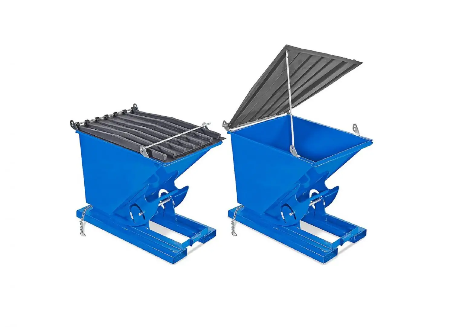
ULINE Lids For Dumping Hoppers Installation Guide
TOOLS NEEDED
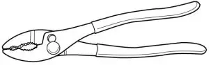
- Pliers

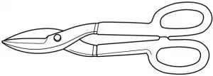
- Tin Snips

- 1/2″ Wrench

- Power Drill

- 3/8″ Drill Bit

PARTS
- Bolt x 8

- Locknut x 8

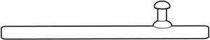
- Hinge/Lock Bar x 2

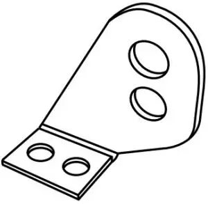
- Right Bracket x 2

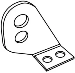
- Left Bracket x 2
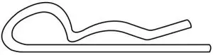
- Cotter Pin x 2

- Lid (2 pieces for H-3508 and H-3509)


SAFETY
![]() WARNING! Ensure that all employees understand and follow these instructions. Failure to read and understand these instructions before installing the lid can result in serious injury.
WARNING! Ensure that all employees understand and follow these instructions. Failure to read and understand these instructions before installing the lid can result in serious injury.
SAFETY INSTRUCTIONS
- ALL contents must be removed from the hopper before any work is performed on the hopper.
- Ensure that all information, safety and warning labels stay in place and remain legible.
- Maintenance and repairs should be done only by personnel qualified to perform the required work.
ASSEMBLY
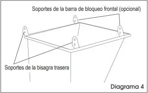
INSTALLING REAR HINGE BRACKETS
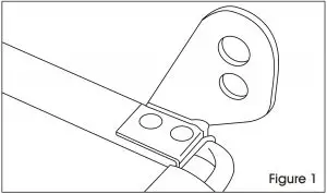
- Line up one right bracket with the rear right side of hopper (See Figure 1)

- Mark centers of the two holes in the bottom of the Remove bracket and drill two 3/8″ holes into the hopper lip.
- Place bracket back on hopper and line up
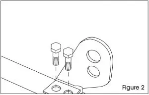
- Secure bracket to hopper lip using 2 bolts and 2 lock (See Figure 2)

- Repeat steps 1-4 with one left bracket on the rear left side of the
INSTALLING FRONT LOCK BAR BRACKETS NOTE: Front lock bar brackets only need to be installed if you are going to be using the lock bar to lock the lid
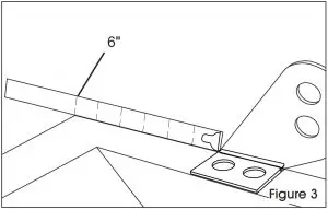
 - Measure 6″ back from the front right side of the (See Figure 3)

- Repeat steps 2-4 to install one right bracket.
- Repeat steps 6-7 with one left bracket on the front left side of the hopper. (See Figure 4)

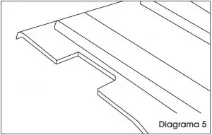
INSTALLING THE LID - The shape of the lid should allow it to fit inside all 4 brackets, but it might be necessary to cut small notches out of the lid for it to fit (See Figure 5) NOTE: In hoppers with two-piece design, there will be a right and left lid.
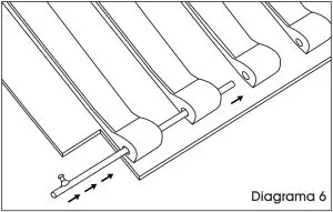
- Insert hinge bar through all lid hinge (See Figure 6)
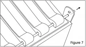
- Slide hinge bar into bottom hole of right hinge (See Figure 7)

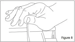
- On the opposite side, push stop pin away from left hinge (See Figure 8)

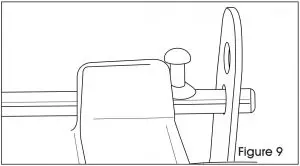
- When pin clears bracket, push pin down and align hinge bar in bracket hole. Let hinge bar slide into bottom bracket (See Figure 9)
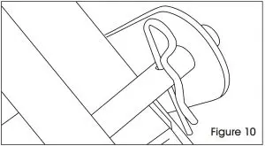
- Insert cotter pin through hinge bar hole near the right hinge bracket. (See Figure 10)

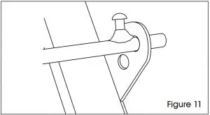
- Follow steps 10-13 to install the lock bar, except lock bar goes into the top hole of bracket. (See Figure 11)
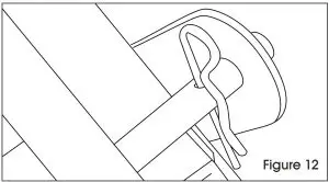
- Insert cotter pin (or padlock, not included) to secure lock (See Figure 12)
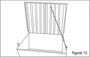
- Lock bars can also be used as a lid prop by inserting the stop pin into the lock bar bracket (See Figure 13)

Contact Us
Phone: 1-800-295-5510
Web: uline.com