REER micron PHOTOELECTRIC MEASUREMENT LIGHT CURTAIN
Micron light curtains MUST NOT be used as safety devices for protection of operators in hazardous areas.
INTRODUCTION
The Micron photoelectric light curtain is a multi-beam optoelectronic system consisting of an emitter and a receiver, used to detect or measure objects.
The two units can be synchronized via optical link or cable.
The status of the light curtain outputs (which reside in the receiver) changes as soon as a measurement is performed (or an object is detected).
Beam positioning
The following figure shows the arrangement of the beams and their numbering:
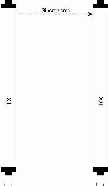
Figure 1
- Beam n (sync)
- Beam n-1
- Beam 6
- Beam 5
- Beam 4
- Beam 3
- Beam 2
- Beam 1
➔ Note that beams must always be numbered starting from the bottom, as shown in figure 1. If synchronized via cable, the last beam can also be used for measurements.
➔ With optical synchronization, the uppermost beam must never be obstructed as this would interrupt the measurement function.
Working range
Particular operating conditions may affect the sensing level of photo-electric devices. In environments characterized by fog, rain, fumes or dust, to always guarantee correct operation of the appliance, it is advisable to apply suitable correction factors Cf so as to maximum working range values. In these cases:
Pu = Pm x Fc
where Pu and Pm are, respectively, the working and maximum range expressed in meters.
The recommended correction factors CF are indicated in the table below.
| OPERATING CONDITIONS | CORRECTION FACTOR Cf |
| Fog | 0.25 |
| Vapors | 0.50 |
| Dust | 0.50 |
| Dense fumes | 0.25 |
➔If the device is installed in environments characterized by sudden changes in temperature, suitable precautions must be taken to prevent the formation of condensation on the mirrors, which could impair detection capability.
ELECTRICAL CONNECTIONS
- Perform the connections as shown in below tables, in order to ensure the correct functioning of the barrier.
- We recommend the use of separate power supplies for the barrier and for other electrical power equipment (electric motors, inverters, frequency converters) or other sources of disturbance.
- We recommend the use of a shielded cable for the connection of serial RS-485 (Micron B).
Emitter connections (AV/AC/B models)
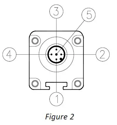
| PIN | COLOUR | NAME | TYPE | DESCRIPTION |
| 1 | Brown | 24VDC | – | 24 VDC power supply |
| 2 | White | RANGE | INPUT | 24 VDC input è HIGH range 0 DC input è LOW range |
| 3 | Blue | 0VDC | – | 0 VDC power supply |
| 4 | Black | SYNC | INPUT | RX-TX SYNC INPUT (OPTIONAL) |
| 5 | Grey | PE | – | Ground connection |
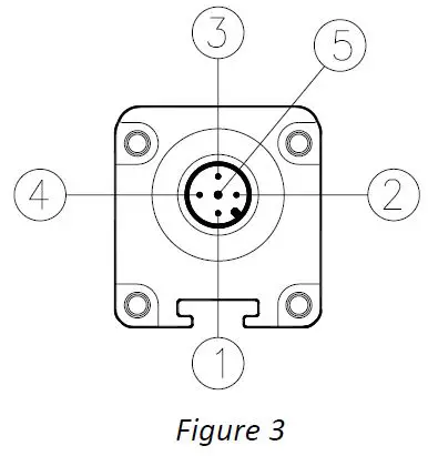
Table 1 – M12, 5-pole
Emitter connections (C models)
| PIN | COLOUR | NAME | TYPE | DESCRIPTION |
| 1 | Brown | 24VDC | – | 24 VDC power supply |
| 2 | White | RANGE | INPUT | 24 VDC input è HIGH range 0 DC input è LOW range |
| 3 | Blue | 0VDC | – | 0 VDC power supply |
| 4 | Black | – | – | Not used |
| 5 | Grey | PE | – | Ground connection |
Table 2 – M12, 5-pole
Receiver connections (AV/AC models)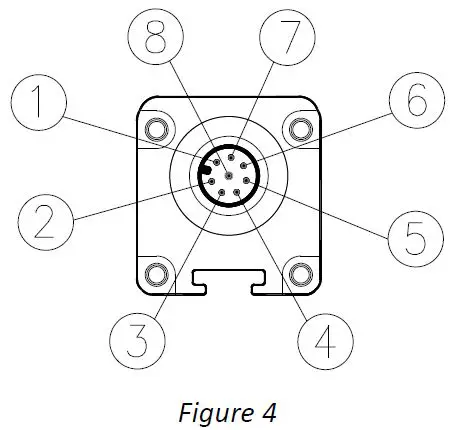
| PIN | COLOUR | NAME | TYPE | DESCRIPTION | OPERATION |
| 1 | White | OUT2/SYNC | OUTPUT | Static output 2 / RX-TX sync | 24 VDC, 100 mA |
| 2 | Brown | 24VDC | – | 24 VDC power supply | – |
| 3 | Green | OUT1 | OUTPUT | Static output 1 | 24 VDC, 100 mA |
| 4 | Yellow | INPUT | INPUT | Input with programmable functions | Compliant with EN 61131-2 |
| 5 | Grey | ANALOG_OUT2 | OUT | Analog output 2 (AC) | 4÷20 mA current output * |
| Analog output 2 (AV) | 0÷10 VDC voltage output * | ||||
| 6 | Pink | ANALOG_OUT1 | OUT | Analog output 1 (AC) | 4÷20 mA current output * |
| Analog output 1 (AV) | 0÷10 VDC voltage output * | ||||
| 7 | Blue | 0VDC | – | 0 VDC power supply | – |
| 8 | Red | PE | – | Ground connection | – |
Table 3 – M12, 8-pole RX
* (Refers to 0 VDC, pin 7)
Receiver connections (B models)
| PIN | COLOUR | NAME | TYPE | DESCRIPTION | OPERATION |
| 1 | White | OUT2/SYNC | OUTPUT | Static output 2 / RX-TX sync | 24 VDC, 100 mA |
| 2 | Brown | 24VDC | – | 24 VDC power supply | – |
| 3 | Green | OUT1 | OUTPUT | Static output 1 | 24 VDC, 100 mA |
| 4 | Yellow | INPUT | INPUT | Input with programmable functions | Compliant with EN 61131-2 |
| 5 | Grey | LINE – (A) | IN/OUT | RS485 -(A) serial line | RS-485 |
| 6 | Pink | LINE + (B) | IN/OUT | RS485 +(B) serial line | RS-485 |
| 7 | Blue | 0VDC | – | 0 VDC power supply | – |
| 8 | Red | PE | – | Ground connection | – |
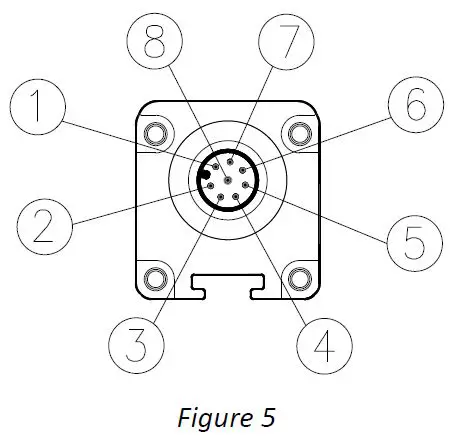
Table 4 – M12, 8-pole RX
Receiver connections (C models)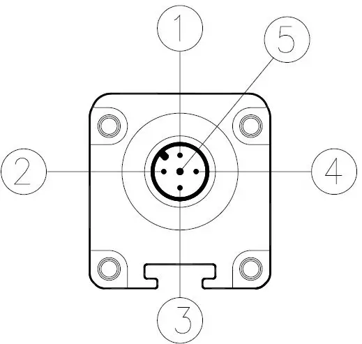
| PIN | COLOUR | NAME | TYPE | DESCRIPTION | OPERATION |
| 1 | Brown | 24 VDC | – | 24 VDC power supply | – |
| 2 | White | OUT2 | OUTPUT | Static output 2 | DARK-ON 24 VDC, 100 mA |
| 3 | Blue | 0 VDC | – | 0 VDC power supply | – |
| 4 | Black | OUT1 | OUTPUT | Static output 1 | LIGHT-ON 24 VDC, 100 mA |
| 5 | Grey | PE | – | Ground connection | – |
Table 5 – M12, 5-pole RX (C models)
Micron-PC connection via USB cable (ReeR CSU M5 – 1250900)
AC/AV/B models are fitted with an M5 connector (leading from the receiver) for connecting the light curtain to a PC on which the Micron configuration SW is installed.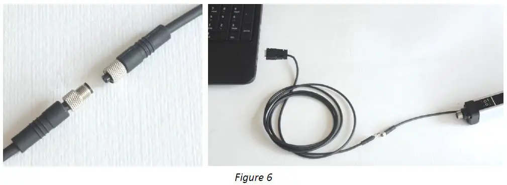
First, connect the M5 connector to the light curtain, then insert the USB connector into the PC.
Push-Pull Outputs (models with step 10mm, 20mm, 30mm STANDARD MODELS)
The models with step 10mm, 20mm, 30mm STANDARD (not H models) are provided with digital outputs 0-24VDC Push-Pull type.
These outputs can operate both in PNP and NPN mode. At the power-on the barrier recognizes the type of connection of the load and operates accordingly.
The two outputs are independent and can be connected to a load such as a PNP and the other to a load NPN. The figure below shows all the possible connections.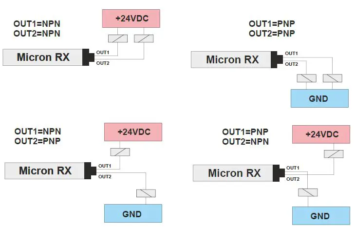 Warning: it is essential to turn off and on the barrier Micron after changing the output connections.
Warnings about connection cables
- Cables must not be more than 50m long.
- Keep the power supply to the light curtain separate from that to other electric power equipment (electric motors, inverters, frequency converters) or other sources of disturbance.
- Connect the emitter and the receiver to the ground socket.
- Connection cables must follow different paths from other power cables.
The emitter, the receiver and the device connected to the outputs must have the ground (0 VDC) connection in common.
INDICATOR LAMPS
| EMITTER (AC/AC/B/C) | |
| TRI-COLOUR LEDS (Red/Green/Orange) | MEANING |
| RED | System start. |
| RED BLINKING | FAIL condition |
| GREEN | Normal operation. At power on:
|
| ORANGE BLINKING | No synchronization via cable |
| RECEIVER (AC/AV/B) | ||
| BI-COLOUR (Red/Green) | BI-COLOUR (Orange/Blue) | MEANING |
| RED | – | Light curtain obstructed |
| GREEN | – | Light curtain clear |
| – | ORANGE | Connected to PC via USB |
| – | BLUE | Input active/recognition activated |
| – | BLUE BLINKING | Pattern recognition |
| – | BLUE 3 BLINKS | No pattern |
| RED BLINKING | – | FAIL condition |
| RED CONSTANT WITH 1 BREAK | – | No sync |
| RED/GREEN WITH 3 BREAKS | – | Analog Output Overload (AV models) |
| Analog Outputs not connected (AC models) | ||
| RED/GREEN WITH 4 BREAKS | – | Digital Outputs overload or failure(models 10mm, 20mm, 30mm) |
| RECEIVER (C) | ||
| BI-COLOUR (Red/Green) | BI-COLOUR (Orange/Blue) | MEANING |
| RED | – | Light curtain obstructed |
| GREEN | – | Light curtain clear |
| RED BLINKING | – | FAIL condition |
| RED CONSTANT WITH 1 BREAK | – | No sync |
TECHNICAL FEATURES
| Micron 5mm SAFETY CURTAIN TECHNICAL FEATURES | |||
| Model | AV/AC | B | C |
| Operating range (REDUCED) m (selectable from software) | 0¸0,6 / 0,6¸1,5 | 0¸0,6 / 0,6¸1,5 | 0¸1 / 0,6¸2,5 |
| Operating range (NORMAL) m (selectable from software) | 0¸1 / 0,6¸2,5 | 0¸1 / 0,6¸2,5 | |
| Power supply VDC | 24 ± 20% | 24 ± 20% | 24 ± 20% |
| Connections | M12 – 5-pole emitter / M12 – 8-pole receiver M5 – 4-pole connector (USB) for software configuration | M12 – 5-pole emitter / M12 – 8-pole receiver M5 – 4-pole connector (USB) for software configuration | M12 – 5-pole emitter / M12 – 5-pole receiver |
| Measurement time | (70 us * number of beams + 500 us)n (n = 1÷3 based on the scan cycles configured) | (70 us * number of beams + 500 us)*2 | |
| Synchronization | Optical or via cable, selectable | Optical | |
| Max power W | 1 (Emitter)/ 2 (Receiver) | 1 (Emitter)/ 2 (Receiver) | 1 (Emitter)/ 2 (Receiver) |
| Digital outputs | 2 static outputs: 100 mA @ 24 VDC PNP(configurable functions) | 2 static outputs: 100 mA @ 24 VDC PNP(configurable functions) | 2 static outputs: 100 mA @ 24 VDC PNP(antiviolent logic) |
| Analog outputs (AC MODELS) | 2 current outputs 4÷20 mA + 2% (refers to 0 VDC) (configurable functions) OPERATING WITH 10 ÷ 470 Ohm LOAD RESISTOR | – | – |
| Analog outputs (AV MODELS) | 2 voltage outputs 0÷10 VDC + 2% (Refers to 0 VDC) / 10 mA max (configurable functions) | – | – |
| RS-485 output (B MODELS) | – | Compliant with the RS-485 standard min Baud Rate = 2400 / max Baud Rate =115200 (configurable function) | – |
| Inputs | Input with configurable functions (0/24 VDC) | Input with configurable functions (0/24 VDC) | – |
| Minimum duration of Input signal (ms) | 5 | 5 | – |
| Max. connect. length m | 50 | 50 | 100 |
| Operating temp. °C | -10 ¸ 55°C | -10 ¸ 55°C | -10 ¸ 55°C |
| Protection class | IP 65 – IP 67 | IP 65 – IP 67 | IP 65 – IP 67 |
| Micron 10mm, 20mm, 30mm MEASURE CURTAIN TECHNICAL FEATURES | |||
| Model | AV/AC | B | C |
| Operating range m | 0¸2 / 1¸10 | 0¸2 / 1¸10 | 0¸2 / 1¸10 |
| Power supply VDC | 24 ± 20% | 24 ± 20% | 24 ± 20% |
| Connections | M12 – 5-pole emitter / M12 – 8-pole receiver M5 – 4-pole connector (USB) for software configuration | M12 – 5-pole emitter / M12 – 8-pole receiver M5 – 4-pole connector (USB) for software configuration | M12 – 5-pole emitter / M12 – 5-pole receiver |
| Measurement time | (70 us number of beams + 500 us) (n = 1÷3 based on the scan cycles configured) | (70 us number of beams + 500 us)2 | |
| Synchronization | Optical or via cable, selectable | Optical | |
| Max power W | 1 (Emitter)/ 2 (Receiver) | 1 (Emitter)/ 2 (Receiver) | 1 (Emitter)/ 2 (Receiver) |
| Digital outputs | 2 static outputs: 100 mA @ 24VDC Push-Pull (configurable functions) | 2 static outputs: 100 mA @ 24VDC Push-Pull (configurable functions) | 2 static outputs: 100 mA @ 24VDC Push-Pull(antiviolent logic) |
| Analog outputs (AC MODELS) | 2 current outputs 4÷20 mA + 2% (refers to 0 VDC) (configurable functions) OPERATING WITH 10 ÷ 470 Ohm LOAD RESISTOR | – | – |
| Analog outputs (AV MODELS) | 2 voltage outputs 0÷10 VDC + 2% (Refers to 0 VDC) / 10 mA max (configurable functions) | – | – |
| RS-485 output (B MODELS) | – | Compliant with the RS-485 standard min Baud Rate = 2400 / max Baud Rate =115200 (configurable function) | – |
| Inputs | Input with configurable functions (0/24 VDC) | Input with configurable functions (0/24 VDC) | – |
| Minimum duration of Input signal (ms) | 5 | 5 | – |
| Max. connect. length m | 50 | 50 | 100 |
| Operating temp. °C | -10 ¸ 55°C | -10 ¸ 55°C | -10 ¸ 55°C |
| Protection class | IP 65 – IP 67 | IP 65 – IP 67 | IP 65 – IP 67 |
| Micron 10mm, 30mm (H) MEASURE CURTAIN TECHNICAL FEATURES | |||
| Model | AVH / ACH | BH | CH |
| Operating range (REDUCED) m (selectable from software) | 0¸3 / 0¸8 | 0¸3 / 0¸8 | 0¸8 / 1¸18 |
| Operating range (NORMAL) m (selectable from software) | 0¸8 / 1¸18 | 0¸8 / 1¸18 | |
| Power supply VDC | 24 ± 20% | 24 ± 20% | 24 ± 20% |
| Connections | M12 – 5-pole emitter / M12 – 8-pole receiver M5 – 4-pole connector (USB) for software configuration | M12 – 5-pole emitter / M12 – 8-pole receiver M5 – 4-pole connector (USB) for software configuration | M12 – 5-pole emitter / M12 – 5-pole receiver |
| Measurement time | (70 us * number of beams + 500 us) (n = 1÷3 based on the scan cycles configured) | (70 us number of beams + 500 us)2 | |
| Synchronization | Optical or via cable, selectable | Optical | |
| Max power W | 1 (Emitter)/ 2 (Receiver) | 1 (Emitter)/ 2 (Receiver) | 1 (Emitter)/ 2 (Receiver) |
| Digital outputs | 2 static outputs: 100 mA @ 24 VDC PNP (configurable functions) | 2 static outputs: 100 mA @ 24 VDC PNP (configurable functions) | 2 static outputs: 100 mA @ 24 VDC PNP (antiviolent logic) |
| Analog outputs (AC MODELS) | 2 current outputs 4÷20 mA + 2% (refers to 0 VDC) (configurable functions) OPERATING WITH 10 ÷ 470 Ohm LOAD RESISTOR | – | – |
| Analog outputs (AV MODELS) | 2 voltage outputs 0÷10 VDC + 2% (Refers to 0 VDC) / 10 mA max (configurable functions) | – | – |
| RS-485 output (B MODELS) | – | Compliant with the RS-485 standard min Baud Rate = 2400 / max Baud Rate =115200 (configurable function) | – |
| Inputs | Input with configurable functions (0/24 VDC) | Input with configurable functions (0/24 VDC) | – |
| Minimum duration of Input signal (ms) | 5 | 5 | – |
| Max. connect. length m | 50 | 50 | 100 |
| Operating temp. °C | -10 ¸ 55°C | -10 ¸ 55°C | -10 ¸ 55°C |
| Protection class | IP 65 – IP 67 | IP 65 – IP 67 | IP 65 – IP 67 |
| Micron 25mm, 50mm, 75mm SAFETY CURTAIN TECHNICAL FEATURES | |||
| Model | AV/AC | B | C |
| Operating range (REDUCED) m (selectable from software) | 0¸3 / 0¸8 | 0¸3 / 0¸8 | 0¸8 / 1¸18 |
| Operating range (NORMAL) m (selectable from software) | 0¸8 / 1¸18 | 0¸8 / 1¸18 | |
| Power supply VDC | 24 ± 20% | 24 ± 20% | 24 ± 20% |
| Connections | M12 – 5-pole emitter / M12 – 8-pole receiver M5 – 4-pole connector (USB) for software configuration | M12 – 5-pole emitter / M12 – 8-pole receiver M5 – 4-pole connector (USB) for software configuration | M12 – 5-pole emitter / M12 – 5-pole receiver |
| Measurement time | (70 us number of beams + 500 us)(n = 1÷3 based on the scan cycles configured) | (70 us number of beams + 500 us)2 | |
| Synchronization | Optical or via cable, selectable | Optical | |
| Max power W | 1 (Emitter)/ 2 (Receiver) | 1 (Emitter)/ 2 (Receiver) | 1 (Emitter)/ 2 (Receiver) |
| Digital outputs | 2 static outputs: 100 mA @ 24 VDC PNP (configurable functions) | 2 static outputs: 100 mA @ 24 VDC PNP (configurable functions) | 2 static outputs: 100 mA @ 24 VDC PNP (antiviolent logic) |
| Analog outputs (AC MODELS) | 2 current outputs 4÷20 mA + 2% (refers to 0 VDC) (configurable functions) OPERATING WITH 10 ÷ 470 Ohm LOAD RESISTOR | – | – |
| Analog outputs (AV MODELS) | 2 voltage outputs 0÷10 VDC + 2% (Refers to 0 VDC) / 10 mA max (configurable functions) | – | – |
| RS-485 output (B MODELS) | – | Compliant with the RS-485 standard min Baud Rate = 2400 / max Baud Rate =115200 (configurable function) | – |
| Inputs | Input with configurable functions (0/24 VDC) | Input with configurable functions (0/24 VDC) | – |
| Minimum duration of Input signal(ms) | 5 | 5 | – |
| Max. connect. length m | 50 | 50 | 100 |
| Operating temp. °C | -10 ¸ 55°C | -10 ¸ 55°C | -10 ¸ 55°C |
| Protection class | IP 65 – IP 67 | IP 65 – IP 67 | IP 65 – IP 67 |
| Beam spacing 5 mm | ||||||||||||||||||||||||||||
| Model | 150 | 300 | 450 | 600 | 750 | 900 | 1050 | 1200 | 1350 | 1500 | ||||||||||||||||||
| Measurement height (mm) | 145 | 295 | 445 | 595 | 745 | 895 | 1045 | 1195 | 1345 | 1495 | ||||||||||||||||||
| Number of beams | 30 | 60 | 90 | 120 | 150 | 180 | 210 | 240 | 270 | 300 | ||||||||||||||||||
| Beam spacing 10 mm | ||||||||||||||||||||||||||||
| Model | 151 | 301 | 451 | 601 | 751 | 901 | 1051 | 1201 | 1351 | 1501 | 1651 | 1801 | 1951 | 2101 | 2251 | 2401 | 2551 | 2701 | 2851 | 3001 | ||||||||
| Measurement height (mm) | 140 | 290 | 440 | 590 | 740 | 890 | 1040 | 1190 | 1340 | 1490 | 1640 | 1790 | 1940 | 2090 | 2240 | 2390 | 2540 | 2690 | 2840 | 2990 | ||||||||
| Number of beams | 15 | 30 | 45 | 60 | 75 | 90 | 105 | 120 | 135 | 150 | 165 | 180 | 195 | 210 | 225 | 240 | 255 | 270 | 285 | 300 | ||||||||
| Beam spacing 20 mm | ||||||||||||||||||||||||||||
| Model | 150-20 | 300-20 | 450-20 | 600-20 | 750-20 | 900-20 | 1050-20 | 1200-20 | 1350-20 | 1500-20 | 1650-20 | 1800-20 | 1950-20 | 2100-20 | 2250-20 | 2400-20 | 2550-20 | 2700-20 | 2850-20 | 3000-20 | ||||||||
| Measurement height (mm) | 130 | 280 | 430 | 580 | 730 | 880 | 1030 | 1180 | 1330 | 1480 | 1630 | 1780 | 1930 | 2080 | 2230 | 2380 | 2530 | 2680 | 2830 | 2980 | ||||||||
| Number of beams | 8 | 15 | 23 | 30 | 38 | 45 | 53 | 60 | 68 | 75 | 83 | 90 | 98 | 105 | 113 | 120 | 128 | 135 | 143 | 150 | ||||||||
| Beam spacing 25 mm | ||||||||||||||||||||||||||||
| Model | 152 | 302 | 452 | 602 | 752 | 902 | 1052 | 1202 | 1352 | 1502 | 1652 | 1802 | 1952 | 2102 | 2252 | 2402 | 2552 | 2702 | 2852 | 3002 | ||||||||
| Measurement height (mm) | 125 | 275 | 425 | 575 | 725 | 875 | 1025 | 1175 | 1325 | 1475 | 1625 | 1775 | 1925 | 2075 | 2225 | 2375 | 2525 | 2675 | 2825 | 2975 | ||||||||
| Number of beams | 6 | 12 | 18 | 24 | 30 | 36 | 42 | 48 | 54 | 60 | 66 | 72 | 78 | 84 | 90 | 96 | 102 | 108 | 114 | 120 | ||||||||
| Beam spacing 30 mm | ||||||||||||||||||||||||||||
| Model | 153 | 303 | 453 | 603 | 753 | 903 | 1053 | 1203 | 1353 | 1503 | 1653 | 1803 | 1953 | 2103 | 2253 | 2403 | 2553 | 2703 | 2853 | 3003 | ||||||||
| Measurement height (mm) | 120 | 270 | 420 | 570 | 720 | 870 | 1020 | 1170 | 1320 | 1470 | 1620 | 1770 | 1920 | 2070 | 2220 | 2370 | 2520 | 2670 | 2820 | 2970 | ||||||||
| Number of beams | 5 | 10 | 15 | 20 | 25 | 30 | 35 | 40 | 45 | 50 | 55 | 60 | 65 | 70 | 75 | 80 | 85 | 90 | 95 | 100 | ||||||||
| Beam spacing 50 mm | ||||||||||||||||||||||||||||
| Model | 155 | 305 | 455 | 605 | 755 | 905 | 1055 | 1205 | 1355 | 1505 | 1655 | 1805 | 1955 | 2105 | 2255 | 2405 | 2555 | 2705 | 2855 | 3005 | ||||||||
| Measurement height (mm) | 100 | 250 | 400 | 550 | 700 | 850 | 1000 | 1150 | 1300 | 1450 | 1600 | 1750 | 1900 | 2050 | 2200 | 2350 | 2500 | 2650 | 2800 | 2950 | ||||||||
| Number of beams | 3 | 6 | 9 | 12 | 15 | 18 | 21 | 24 | 27 | 30 | 33 | 36 | 39 | 42 | 45 | 48 | 51 | 54 | 57 | 60 | ||||||||
| Beam spacing 75 mm | ||||||||||||||||||||||||||||
| Model | 157 | 307 | 457 | 607 | 757 | 907 | 1057 | 1207 | 1357 | 1507 | 1657 | 1807 | 1957 | 2107 | 2257 | 2407 | 2557 | 2707 | 2857 | 3007 | ||||||||
| Measurement height (mm) | 75 | 225 | 375 | 525 | 675 | 825 | 975 | 1125 | 1275 | 1425 | 1575 | 1725 | 1875 | 2025 | 2175 | 2325 | 2475 | 2625 | 2775 | 2925 | ||||||||
| Number of beams | 2 | 4 | 6 | 8 | 10 | 12 | 14 | 16 | 18 | 20 | 22 | 24 | 26 | 28 | 30 | 32 | 34 | 36 | 38 | 40 | ||||||||
| 150 | 300 | 450 | 600 | 750 | 900 | 1050 | 1200 | 1350 | 1500 | 1650 | 1800 | 1950 | 2100 | 2250 | 2400 | 2550 | 2700 | 2850 | 3000 | |
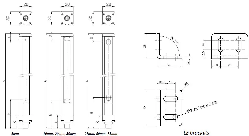
| Dimension A | 213 | 363 | 513 | 663 | 813 | 963 | 1113 | 1263 | 1413 | 1563 | 1713 | 1863 | 2013 | 2163 | 2313 | 2463 | 2613 | 2763 | 2913 | 3063 |
| Dimension A (step 5mm) | 223 | 373 | 523 | 673 | 823 | 973 | 1123 | 1273 | 1423 | 1573 | – | – | – | – | – | – | – | – | – | – |
| Dimension B (step 5mm) | 64,5 | 64,5 | 64,5 | 64,5 | 64,5 | 64,5 | 64,5 | 64,5 | 64,5 | 64,5 | – | – | – | – | – | – | – | – | – | – |
| Dimension B (step 10mm, 20mm, 30mm) | 61,5 | 61,5 | 61,5 | 61,5 | 61,5 | 61,5 | 61,5 | 61,5 | 61,5 | 61,5 | 61,5 | 61,5 | 61,5 | 61,5 | 61,5 | 61,5 | 61,5 | 61,5 | 61,5 | 61,5 |
| Dimension B (step 25mm, 50mm, 75mm) | 69 | 69 | 69 | 69 | 69 | 69 | 69 | 69 | 69 | 69 | 69 | 69 | 69 | 69 | 69 | 69 | 69 | 69 | 69 | 69 |
| Dimension C | 29 | 29 | 29 | 29 | 29 | 29 | 29 | 29 | 29 | 29 | 29 | 29 | 29 | 29 | 29 | 29 | 29 | 29 | 29 | 29 |
| Dimension D (step 5mm) | 13 | 13 | 13 | 13 | 13 | 13 | 13 | 13 | 13 | 13 | – | – | – | – | – | – | – | – | – | – |
| Dimension D (step 10mm) | 11 | 11 | 11 | 11 | 11 | 11 | 11 | 11 | 11 | 11 | 11 | 11 | 11 | 11 | 11 | 11 | 11 | 11 | 11 | 11 |
| Dimension D (step 20mm) | 11 | 21 | 11 | 21 | 11 | 21 | 11 | 21 | 11 | 21 | 11 | 21 | 11 | 21 | 11 | 21 | 11 | 21 | 11 | 21 |
| Dimension D (step 25mm) | 19 | 19 | 19 | 19 | 19 | 19 | 19 | 19 | 19 | 19 | 19 | 19 | 19 | 19 | 19 | 19 | 19 | 19 | 19 | 19 |
| Dimension D (step 30mm) | 31 | 31 | 31 | 31 | 31 | 31 | 31 | 31 | 31 | 31 | 31 | 31 | 31 | 31 | 31 | 31 | 31 | 31 | 31 | 31 |
| Dimension D (step 50mm) | 44 | 44 | 44 | 44 | 44 | 44 | 44 | 44 | 44 | 44 | 44 | 44 | 44 | 44 | 44 | 44 | 44 | 44 | 44 | 44 |
| Dimension D (step 75mm) | 69 | 69 | 69 | 69 | 69 | 69 | 69 | 69 | 69 | 69 | 69 | 69 | 69 | 69 | 69 | 69 | 69 | 69 | 69 | 69 |
| Mounting | 2 LE TYPE brackets with 2 inserts | 3 LE TYPE brackets with 2 inserts | ||||||||||||||||||
CONFIGURATION SOFTWARE
Using the ReeR MICRONCONFIGURATOR program
The Micron is provided with a connector on the receiver (see the connections section) for connection to a PC via USB link.
The function programming system (ReeR MICRONCONFIGURATOR) can be used to configure the Micron by setting the conditions for activating the outputs (these can also be combined by using the NULL/AND/OR operators). The following conditions can be selected:
- FBO First beam obstructed
- LBO Last beam obstructed
- CBO Central beam obstructed *
- NBO Number of beams obstructed
- NCBO Maximum number of consecutive beams obstructed *
- BNO Beam n obstructed
- If more than one zone is obstructed, the data refer to the zone with the highest number of obstructed beams.
A graphic interface can also be displayed for real-time monitoring of light curtain conditions. The following figures illustrate some screen pages of the ReeR Micron Configurator program which can be used to configure the Micron’s operating logic.
Preliminary Operations
Insert the MICRONCONFIGURATOR CD-ROM in the computer and follow the software installation instructions. To launch Micron Configurator, double-click the icon created on the desktop.
- LIGHT CURTAIN MODEL AND DATA
- Micron
INITIAL CONFIGURATION (1)
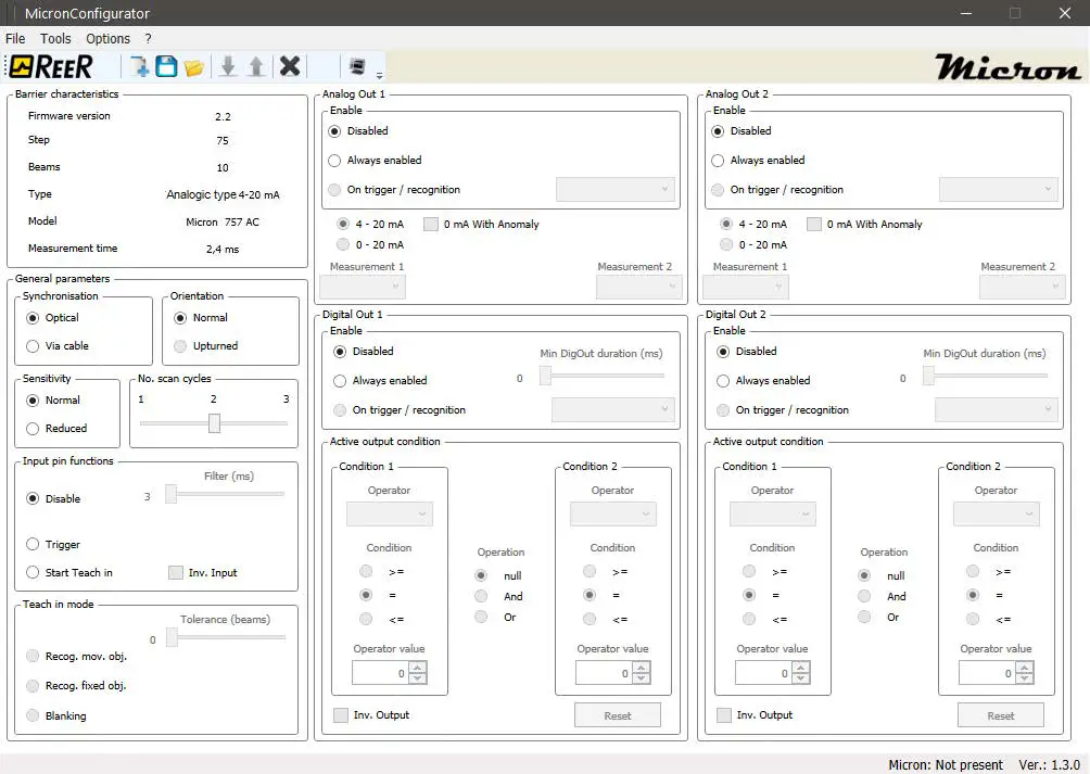 Figure 10
Even if the light curtain is not connected you can still fill in the configuration fields and save the configuration on the PC, using the icon. You will be able to retrieve the previously saved configuration later, by clicking .
Connecting/disconnecting the light curtain
The “Barrier characteristics” panel in the top left corner is filled in automatically a few seconds after establishing the USB connection.
- Click (upload) to send the configuration to the Micron: at the end of this procedure the light curtain will automatically restart using the new configuration.
- Click (download) to read the configuration on the Micron; the program will display the data relating to the retrieved configuration.
Initial configuration
Sync configuration:
TX-RX synchronization can be programmed as follows:
| SYNC VIA CABLE | Connect the SYNC signals of the emitter and the receiver. |
| OPTICAL SYNC | Sync the devices using the last beam of the light curtain. |
- With optical synchronization, the uppermost beam must never be obstructed otherwise the measurement function will be interrupted.
- With cable synchronization, digital output 2 cannot be used.
- To switch from cable to optical synchronization, the emitter must be switched off and then restarted.
Receiver sensitivity configuration (only models 25mm, 50mm, 75mm, 10mm H, 30mm H):
The receiver’s sensitivity can be adjusted depending on its distance from the emitter.
| NORMAL SENSITIVITY | Recommended for d > 50 cm |
| REDUCED SENSITIVITY | Recommended for d < 50 cm |
With reduced sensitivity it is advisable to select the low range on the emitter.
Orientation configuration:
Beam numbering can be configured according to the orientation of the light curtain:
| NORMAL ORIENTATION | Connectors low – first beam at bottom |
| UPTURNED ORIENTATION | Connectors high – first beam at bottom |
With optical synchronization light curtain orientation must be normal.
Scan cycle configuration:
The number of cycles used to perform the measurement can be configured:
| 1 | Single cycle: fast but inaccurate measurement sensitive to light disturbance |
| 2 | two cycles: measurement with good speed-precision balance |
| 3 | three cycles: accurate measurement, insensitive to light disturbance but slower |
Measurement time depends on the number of programmed cycles according to the formula:
(0,07ms * number of beams + 500 us)*n ms
(n configurable 1÷3 based on the scan cycles configured).
- INPUT PIN CONFIGURATION (2)

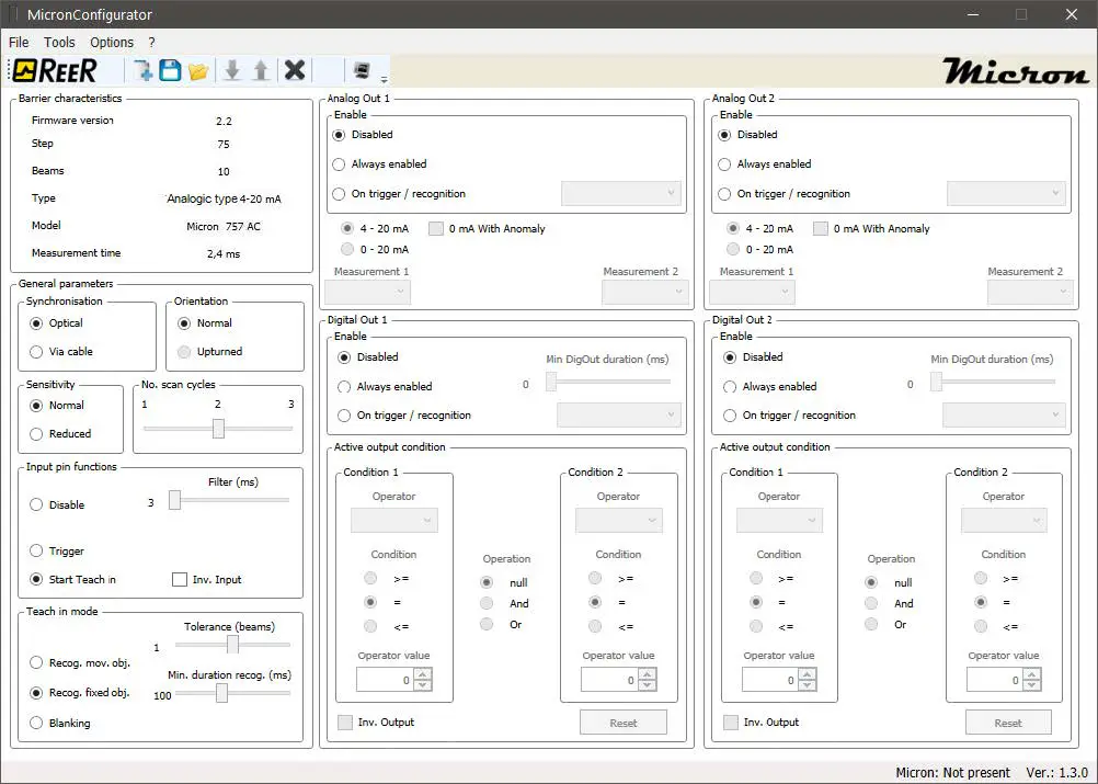
Input pin configuration
The input pin can be configured as follows:
- No function (disabled).
- Trigger function: this can be used to enable analog and digital outputs, stand-by and start/stop measurements. In this mode the minimum internal trigger time can be set to between 0 and 250 ms.(The BLUE LED lights up to indicate that the input is active).
- Teach-in function The pin can be used to teach the light curtain the pattern of an object using the following procedure:
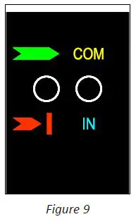
ACTION BLUE LED 1 No pattern Blue LED blinks three times 2 Connect the input pin to 24 VDC Blue LED blinks continuously 3 Enter the object to be recognized in the light curtain’s measurement field Blue LED blinks continuously 4 Disconnect the input pin Blue LED blinks twice followed by a light curtain auto-reset procedure 5 Recognition active Blue LED constantly on To delete the pattern of the object that has been saved, repeat the procedure described above with the measurement field empty.
For recognition mode please refer to the relevant chapter.
The filter on the input pin can be set to between 3 and 250 ms (impulses shorter than the set value are not considered). This signal is active high but the logic can be inverted (active low) using the Inv. Input box.
TEACH IN mode
When the input pin is configured as Teach in the “Teach in mode” panel is active.
Teach in mode is used when the light curtain must recognize a specific object or pattern. There are three possible options:
| MODE | DESCRIPTION | |
| 1 | Recognition of a moving object | The object to be recognized must be compact (with no transparent parts) and obstruct a certain number of adjacent beams. The light curtain recognizes the object saved previously in any position within the measurement field. |
| 2 | Recognition of a fixed object (pattern) | The object to be recognized can be of any shape, it need not be continuous and may have transparent parts. The light curtain only recognizes the object if it obstructs the same position (in the measurement field) as when it was saved. |
| 3 | Blanking | The object to be recognized can be of any shape, it need not be continuous and may have transparent parts. In this case it will be parts of a machine (guards, arms, etc.) that obstruct part of the field of vision. The light curtain treats the object as non-existent and ignores it in the measurements. |
- In cases 1 and 2, the blue LED blinks to indicate that the object has been recognized. Recognition generates an internal trigger logic signal which can thus be used to activate outputs, enable stand by, etc.
- It is possible to select a tolerance of 0 to 2 beams for recognition.
- With particularly fast-moving objects, the minimum length of the internal trigger signal can be set to between 0 and 250 ms.
- The light curtain is capable of saving 2 different patterns for modes 1 and 2.
- Click to delete previously saved patterns.
TEACH IN mode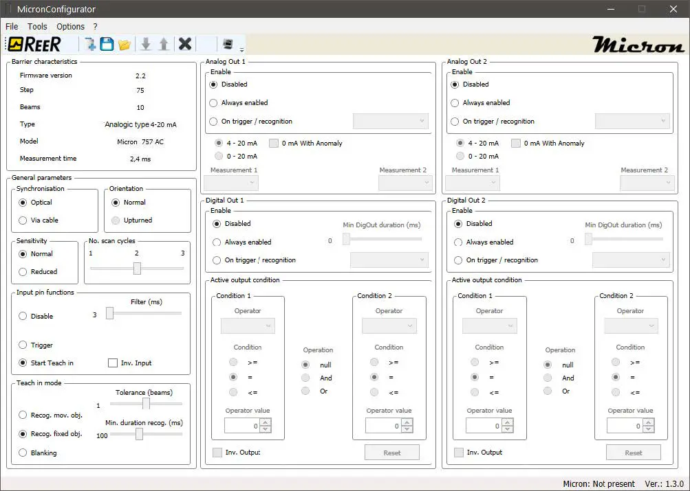
Analog output configuration (AC/AV models)
ANALOG OUTPUT CONFIGURATION
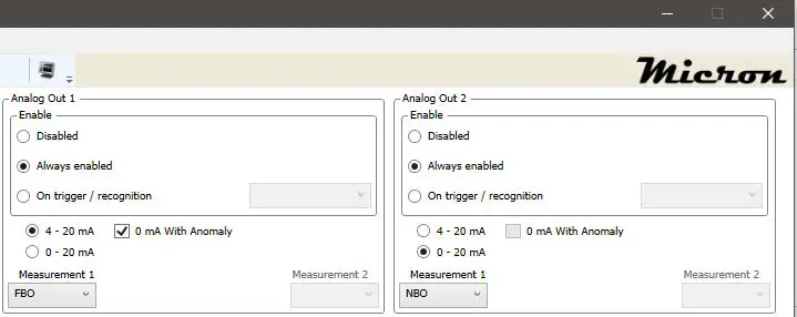 Figure 13
It is possible to configure the conditions for activating each single output.
Use the “ENABLE” box to select the conditions for activating each analog output.
| MODE | DESCRIPTION | |
| 1 | Output disabled | The output is not active and gives 0 V in AV models and 4 mA in AC models |
| 2 | Output always enabled | The output always gives the analog value for the measurement selected. |
| 3 | Upon trigger/recognition | CHOOSE BETWEEN: |
| a. | Enable | With input not active/object not recognized the output gives 0 V in AV models and 4 mA in AC models With input active/object recognized the output continuously gives the analog value corresponding to the measurement detected. |
| b. | Stand by | With input not active/object not recognized the output continuously gives the analog value corresponding to the measurement detected. With input active/object recognized the output keeps the last value given. |
|
c. |
Start/stop | With input active/object recognized the light curtain starts a measurement session by saving the highest value of the selected measurement. When input deactivated/object not recognized, the output gives the analog value corresponding to the maximum value detected for the selected measurement. This value stays on the output until the next Start/stop session. |
| d. | Switch measurement | With input not active/object not recognized the output continuously gives the analog value corresponding to the measurement selected in the Measurement 1 box. With input active/object recognized the output continuously gives the analog value corresponding to the measurement selected in the Measurement 2 box. |
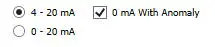
With Micron AC is possible to choose the current range for each output:
- 4-20mA
- 0-20mA
If the output current is 4-20mA, in case of anomaly, you can choose if the barrier should provide 0mA (default 4mA).
The following measurements can be selected to apply to the output:
- FBO First beam obstructed
- LBO Last beam obstructed
- CBO Central beam obstructed
- NBO Number of beams obstructed
- NCBO Maximum number of consecutive beams obstructed
AV light curtains output a voltage that is proportionate to the measurement performed according to the following formula:
Vo=((10V/number of beams)*measurement) + 2%
E.g.: with a 30-beam light curtain and an NBO measurement of 15, the Micron outputs:
Vo=((10V/30)*15) + 2%=5V + 2%
AC light curtains output a current that is proportionate to the measurement performed according to the following formula, based on the current range chosen:
4-20mA:
Io=(((16mA/number of beams)*measurement)+4mA) + 2%
E.g.: with a 26-beam light curtain and an LBO measurement of 13, the Micron outputs:
Io=(((16mA/26)*13)+4mA) + 2% =12mA + 2%
0-20mA:
Io=((20mA/number of beams)*measurement) + 2%
E.g.: with a 26-beam light curtain and an LBO measurement of 13, the Micron outputs:
Io=((20mA/26)*13) + 2% =10mA + 2%
Digital output configuration
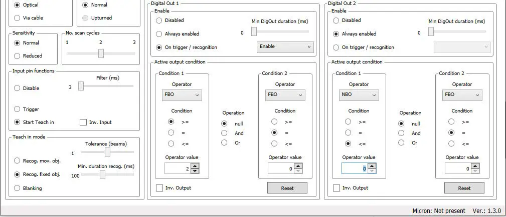
Figure 14
The conditions for activating each digital output can be selected in the “ENABLE” panel.
| MODE | DESCRIPTION | |
| 1 | Output disabled | The output is not active and gives 0 VDC |
| 2 | Output always enabled | The output is active and gives 0 VDC or 24 VDC depending on the set condition. (-> “Active Output Condition” panel) |
| 3 | Upon trigger/recognition | CHOOSE BETWEEN: |
| a. | Enable |
|
| b. | Stand by |
|
|
c. | Start/stop |
|
| d. | Switch condition |
|
| c. | Copy |
|
With fast output switching, the minimum output time can be set to between 0 and 250 ms.
The CONDITION box
The “CONDIZIONE” box can be used to set the condition for switching the output to LL1 (24 VDC): First select operator 1 in the left-hand column.
The program offers a choice of the following conditions:
- FBO First beam obstructed
- LBO Last beam obstructed
- CBO Central beam obstructed
- NBO Number of beams obstructed
- NCBO Maximum number of consecutive beams obstructed
- BNO Beam n obstructed
Select the condition:
- >=
- =
Select the value.
E.g.: 12
Example:
to switch the output to LL1 if the last obstructed beam is more than or equal to 12, select: LBO, >=, 12
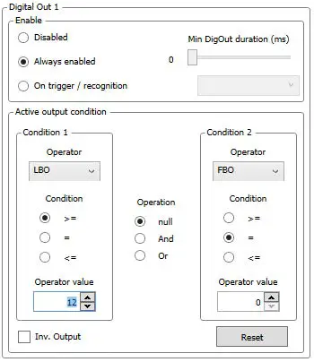 Figure 15
Use the OR and AND operators to define more complex logic conditions and establish relationships between the conditions in the LH column to those in the RH column.
Example:
to switch the output to LL1 if the last obstructed beam is more than or equal to 12, and there are 5 obstructed beams, select: LBO, >=, 12 AND NBO, =, 5
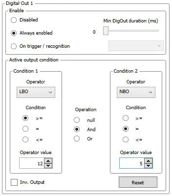 Figure 16
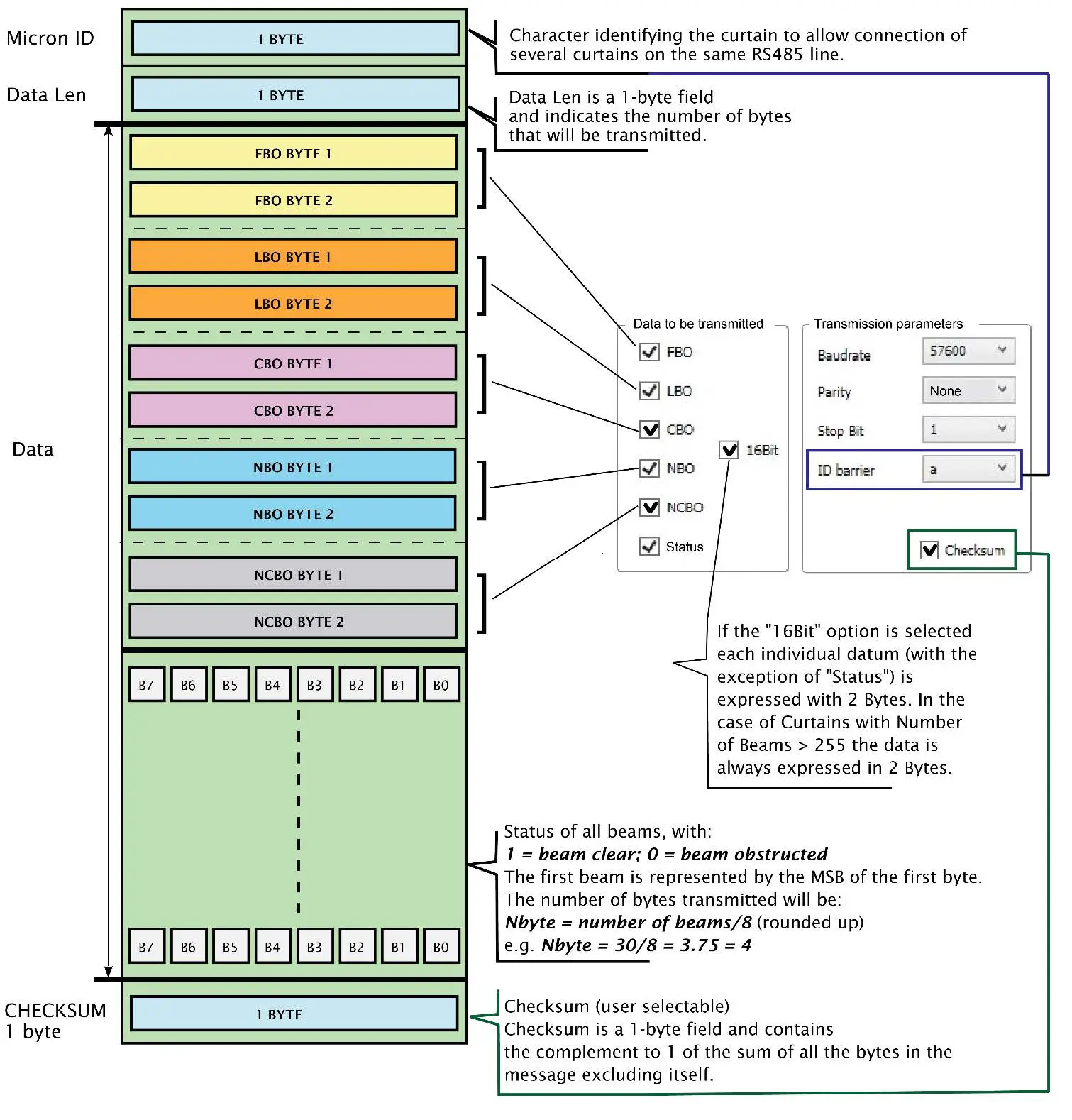
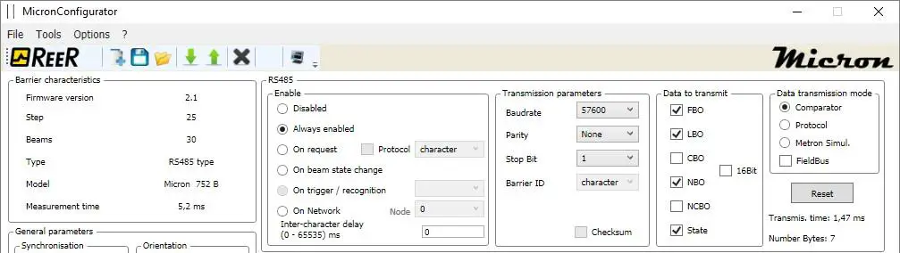
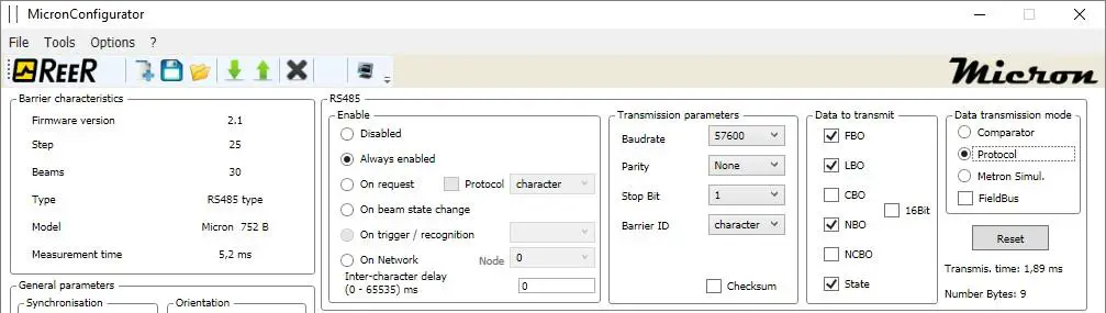
RS485 output configuration (B models)
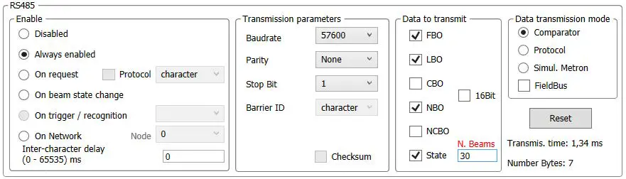
Figure 17
The conditions for activating RS485 serial data transmission can be selected in the “ENABLE” panel.
Enable
| MODE | DESCRIPTION | |
| 1 | RS485 disabled | Data transmission not active |
| 2 | RS485 always enabled | Data transmission always active. In the offline configuration, with “Status” enabled, Microcomb provides a box to enter the number of beams for the calculation of the Transmission Time. When the number of beams is added, the ‘Transmission Time’ is updated in real-time. |
| 3 | RS485 upon request | Data transmission only starts upon recognition of a character that is received. The character is user-definable. It is possible to send the request character encapsulated in a data packet described in protocol mode on the following pages. |
| 4 | RS485 upon beam status change | Data transmission is activated when the beam status changes. |
| 5 | Upon trigger/recognition | CHOOSE BETWEEN: |
| a. | Enable |
|
| b. | Stand by |
|
| c. | Start/stop |
|
| d. | One shot |
|
| 6 | On Network | Up to 3 Micron B can be connected on Network -> Micron on Network |
Inter-character delay: in the case of always active data transmission, the inter-character delay between one data packet and the next can be customized by changing the “INTERCHARACTER DELAY” parameter. The program checks that the selected inter-character delay is compatible with the data transmission parameters. An Inter-character delay of zero indicates that transmission of the next data packet will start as soon as the next measurement is available.
Micron on Network
Micron barrier can be connected on Network; the maximum number of barriers is 3.
- The first barrier will be programmed with node=0.
- The other barriers will have a node sequential and different from 0 numeration.
- The RS-485 outputs (pin 5 or 6) will be connected in parallel.
- The 0V connection must be common.
- No need of termination resistor.
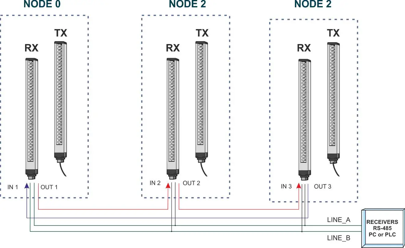
Figure 18
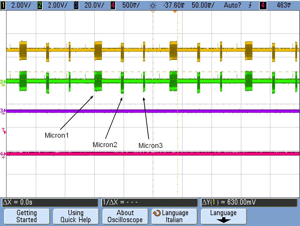
Figure 19 – sequential data transmission on RS-485 outputs
Data transmission parameters
| PARAMETER | DESCRIPTION | |
| 1 | Baudrate | 2400, 4800, 9600, 19200, 38400, 57600, 115200 |
| 2 | Parity | Even, odd, none |
| 3 | Stop bit | 1, 2 |
| 4 | RS485 upon beam status change | Data transmission is activated when the beam status changes. |
| 5 | light curtain ID | This character identifies the light curtain so that several light curtains can be connected on the same RS485 link. |
| 6 | Checksum | In data transmission mode Protocol adds a checksum byte to the data packet |
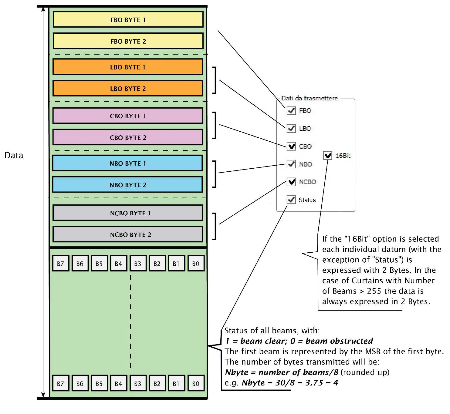
Data to be sent
| FBO | First obstructed beam |
| LBO | Last obstructed beam |
| CBO | Central beam obstructed |
| NBO | Number of obstructed beams |
| NCBO | Maximum number of consecutive beams obstructed |
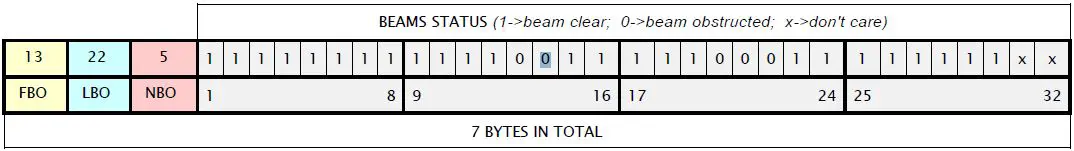
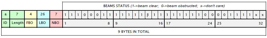
| Status | Status of all beams: 1 corresponds to beam clear, the first beam is represented by the MSB of the first byte. Bits with no corresponding beam are zero. The number of bytes transmitted is given by the number of beams/8 approximated by excess. E.g.: a 26-beam light curtain will send 26/8 = 3.25 -> 4 bytes in which of the last byte only the 2 most significant bits are valid. |
| 16 bit | Provides (when selected) the measures in 16 bit (2 bytes) format |
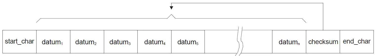
Data transmission mode
In “Comparator” mode the light curtain sends a number of bytes corresponding to the measurements selected in the “Data to be sent” section containing the current value of the measurements.
In “Protocol” mode the light curtain sends a data packet with the following format: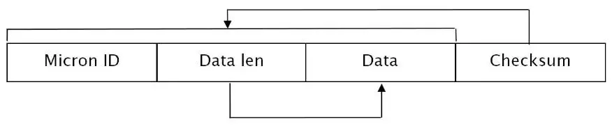
“Micron ID” is a 1-byte field. It contains the character selected in parameter 4 of the “Data transmission parameters” section. “Data Len” is a 1-byte field and contains the number of bytes corresponding to the measurements selected in the “Data to be sent” section.
The “Data” field consists of the number of bytes indicated by the previous Data Len field and contains the current value of the measurements selected in the “Data to be sent” section.
| DATA FORMAT | |
| NUMBER OF BEAMS | DATA FORMAT |
| < 255 | 8 bit |
| > 255 | 16 bit |
“Checksum” is a 1-byte field and contains the complement to 1 of the sum of all the bytes in the message except itself. The Checksum field is only present if selected in the “Data transmission parameters” section.
In “Matron simulation” mode the barrier will send data simulating the METRON B in “Binary” mode.
In “Fieldbus” mode must be selected when the barrier is coupled with a Refer Fieldbus module.
Comparator mode
The following figure shows a scheme of the data packet sent by the light curtain in comparator mode.
Protocol mode
The following figure shows a scheme of the data packet sent by the light curtain in protocol mode.
Example of data packet in comparator mode
Example of data packet in protocol mode
Monitoring light curtain status
AV/AC models
Click “MONITOR” to open a graphic user interface that displays light curtain operation in real time. The following information is given:
- Model and data of the light curtain connected
- Synchronization (optical or via cable)
- Sensitivity
- Orientation (normal or upturned)
- Scan cycles
- Graphic representation of the MICRON beams (in real time)
- Graphic representation of cable synchronization (not displayed with optical synchronization)
- Measurements performed (in real time)
- Input status (in real time)
- Pattern present (in real time)
- Object recognition (in real time)
- Value of analog outputs (in real time)
- Status of digital outputs (in real time)
Next time you click the program returns to the configuration screen page.
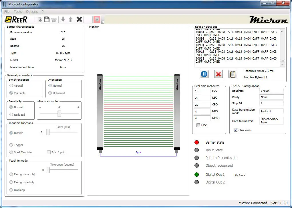
B models
Click “MONITOR” to open a graphic user interface that displays light curtain operation in real time. The following information is given:
- Model and data of the light curtain connected
- Synchronization (optical or via cable)
- Sensitivity
- Orientation (normal or upturned)
- Scan cycles
- Graphic representation of the MICRON beams (in real time)
- Graphic representation of cable synchronization (not displayed with optical synchronization)
- Data sent via the RS485 link (in real time). You may stop the flow of data, delete the contents of the window and copy the data to the Windows clipboard.
- Data transmission time
- RS-485 configuration
- Measurements performed (in real time)
- Input status (in real time)
- Pattern present (in real time)
- Object recognition (in real time)
- Status of digital outputs (in real time)
Next time you click the program returns to the configuration screen page.