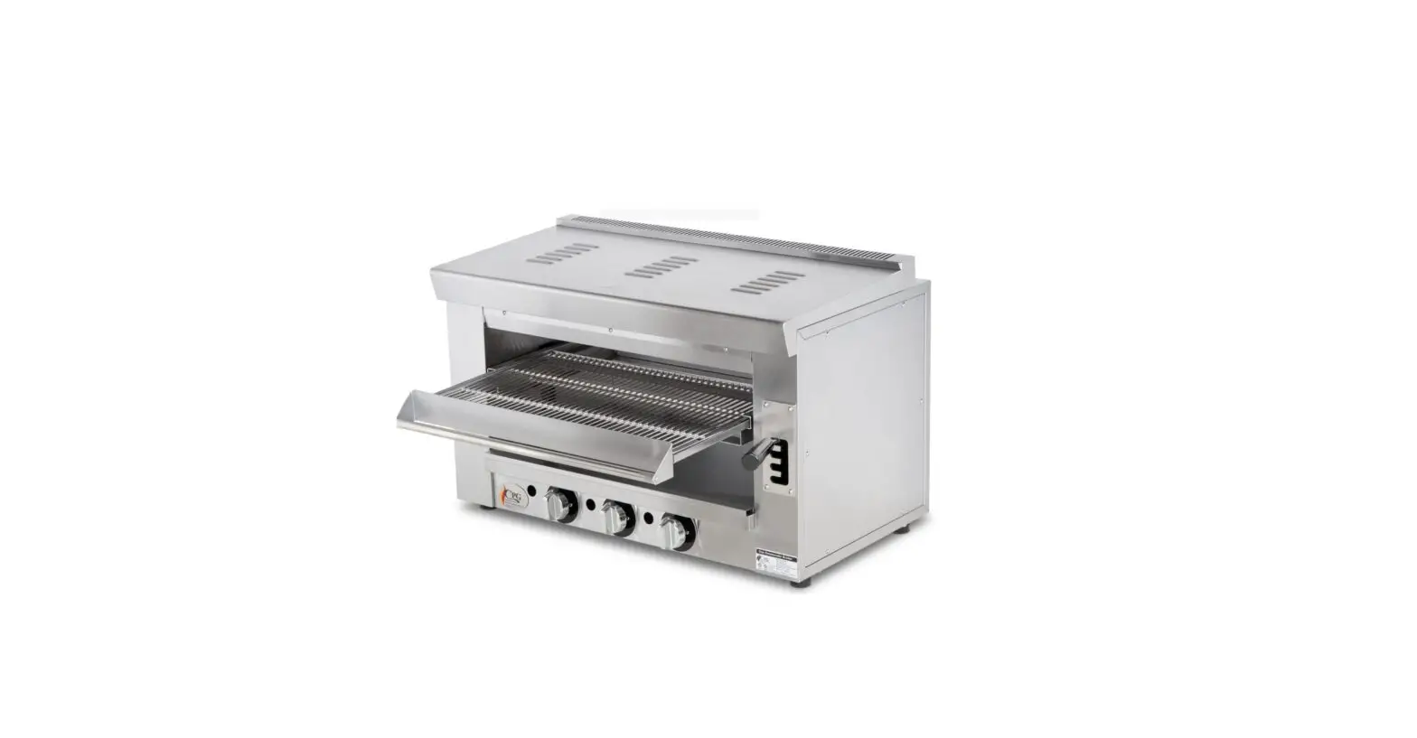
CPG 351S36SBL36K Salamander Gas Broiler Instruction Manual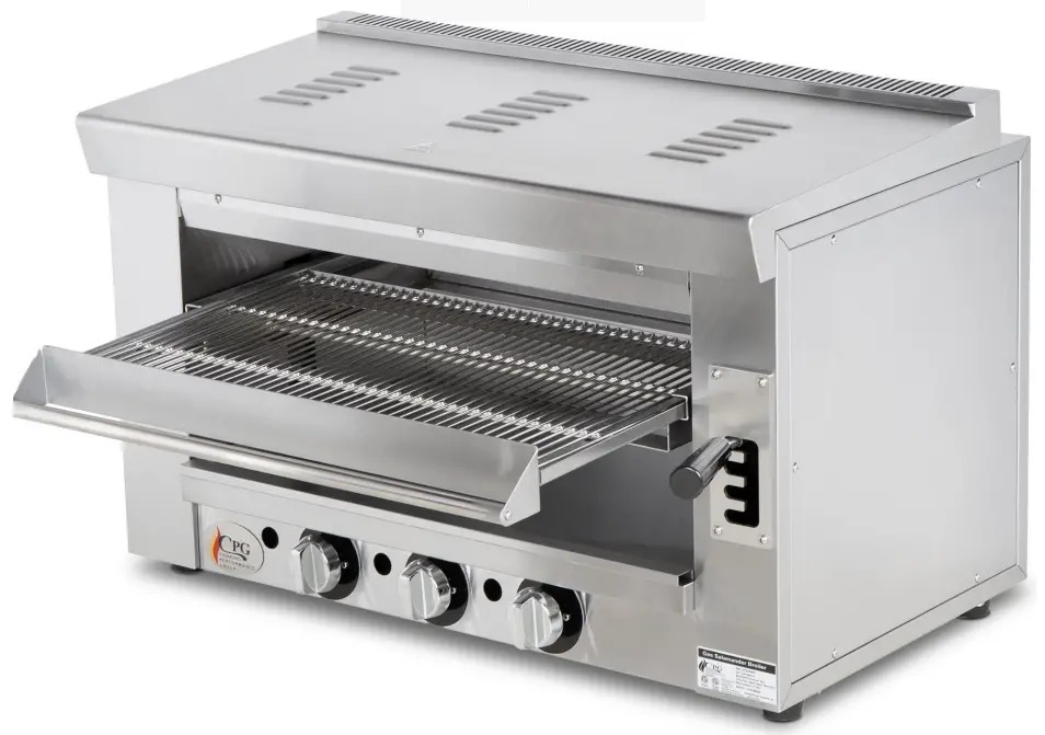
Safety Precautions
CAUTION: Failure to comply with the following operation instructions could lead to potential hazards and/or unsafe practice and could result in injury and damage to product and property
NOTICE: Local codes regarding installation vary greatly from one area to another. The National Fire Protection Association, Inc., states in its NFPA96 latest edition that local codes are “Authority Having Jurisdiction” when it comes to requirement for installation of equipment. Therefore, installation should comply with all local codes. This product is intended for commercial use only. Not for residential use.
WARNING:
- Do not store or use gasoline or other flammable vapors and liquids in the vicinity of this or any other equipment.
- Improper installation, adjustment, alteration, service or maintenance could lead to property damage, injury or death. Read the installation, operating and maintenance instructions thoroughly before installing or servicing CPG equipment. This manual must be retained for future reference.
- A fully licensed installer must handle all maintenance and repair.
GAS PRESSURE: The appliance and its individual shutoff valve (to be supplied by user) must be disconnected from the gas supply piping system during any pressure testing of that system at test pressures in excess of 1/2 PSI (3.45 kPa). The appliance must be isolated from the gas supply piping system by closing its individual manual shut-off valve during any pressure testing of the gas supply piping system at test pressures equal to or less than 1/2 PSI (3.45 kPa)
Parts Diagram – Whole Assembly
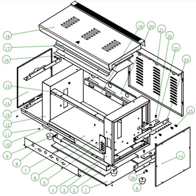
# | Our Item # | Description | QTY |
| 1 | 35134014034 | BASEBOARD | 1 |
| 2 | 35134014036 | COTTON INSULATION PLATE | 1 |
| 3 | 35134014039 | BOTTOM BEAM | 1 |
| 4 | 35134014003 | SIDE PANEL (RIGHT) | 1 |
| 5 | 35134014013 | GEAR PLATE | 1 |
| 6 | 351212221 | BOLT | 4 |
| 7 | 35134014001 | BASEBOARD (BOX) | 1 |
| 8 | 35134014040 | FRONT PANEL | 1 |
| 9 | 351090026 | RUBBER FOOT | 4 |
| 10 | 35134014016 | BAFFLE | 1 |
| 11 | 351210277 | SCREW | – |
| 12 | 35134014004 | SIDE PANEL (LEFT) | 1 |
| 13 | 35134014014 | REINFORCING PLATE (LEFT) | 2 |
| 14 | 35134008012 | SIDE SEALING PLATE (LEFT & RIGHT) | 2 |
| 15 | 35134008007 | FRONT BEAM | 1 |
| 16 | 35134008010 | TOP PANEL (CHAMBER) | 1 |
| 17 | 35134008014 | COTTON PRESSING PLATE (TOP) | 1 |
| 18 | 35134008009 | TOP COVER PLATE | 1 |
| 19 | 35134008039 | SUPPORTING PLATE (PROBE) | 1 |
| 20 | 35134014002 | BACK PANEL (CHAMBER) | 1 |
| 21 | 35134014006 | SIDE SEALING PLATE (BACK) | 1 |
| 22 | 351212427 | BOLT | 8 |
| 23 | 35134008024 | SHAFT PLATE | 4 |
| 24 | 35134014015 | REINFORCING PLATE (RIGHT) | 2 |
| 25 | 351214271 | BOLT | 12 |
| 26 | 351213138 | NUT | – |
| 27* | 35134014021 | MOUNTING KIT – WALL | – |
| 28* | 35128059015 | MOUNTING KIT – S60, S60G24 RANGE | – |
| 29* | 35128051052 | MOUNTING KIT – S36 RANGE | – |
Parts Diagram – Lift Assembly
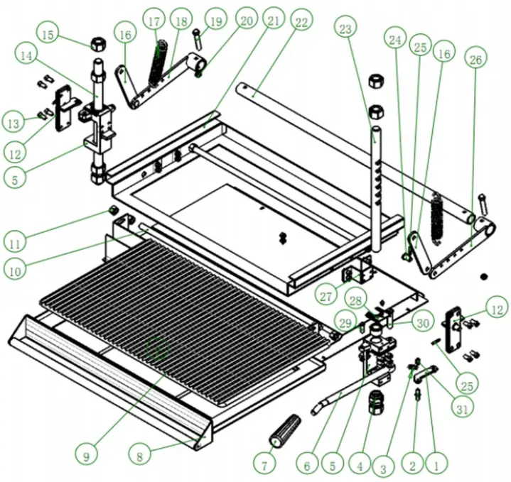
# | Our Item # | Description | QTY |
| 1 | 351201261 | CLAW PLATE | 1 |
| 2 | 351201273 | STOP PIN | 1 |
| 3 | 351080087 | LOCKING TENSION SPRING | 1 |
| 4 | 351201265 | SLIDE BUSHING | 1 |
| 5 | 351201259 | SLIDE BUSHING BASE (RIGHT) | 2 |
| 6 | 351201262 | HANDLE STEM | 1 |
| 7 | 351070161 | HANDLE COVER | 1 |
| 8 | 35134014005 | RACK SUPPORTING ASSEMBLY | 1 |
| 9 | 351110668 | RACK | 1 |
| 10 | 351201276 | SCREW | 1 |
| 11 | 351210038 | NUT | 8 |
| 12 | 35134014001 | COVER PLATE ASSEMBLY (RIGHT SLIDE BUSHING) | 2 |
| 13 | 351212221 | SCREW | 24 |
| 14 | 351201264 | SLIDE SHAFT (LEFT) | 1 |
| 15 | 351210057 | NUT | 8 |
| 16 | 35134014027 | CONNECTING ROD | 2 |
| 17 | 351080088 | LIFTING TENSION SPRING | 2 |
| 18 | 35134014004 | ARM ASSEMBLY (LEFT) | 1 |
| 19 | 351214197 | BOLT | 2 |
| 20 | 351213139 | NUT | 4 |
| 21 | 35134014007 | LIFTING CHASSIS | 1 |
| 22 | 351040286 | CONNECTING SHAFT | 1 |
| 23 | 351201263 | SLIDE SHAFT (RIGHT) | 1 |
| 24 | 351201274 | SHAFT PIN | 2 |
| 25 | 351214205 | COTTER PIN | 4 |
| 26 | 35134014003 | ARM ASSEMBLY (RIGHT) | 1 |
| 27 | 35134014008 | CONNECTING PLATE (CHASSIS) | 1 |
| 28 | 35134014031 | PRESSING PLATE (SLIDE BUSHING) | 2 |
| 29 | 351210295 | SCREW | 1 |
| 30 | 351201266 | SHAFT PIN (OPERATING LEVER) | 1 |
| 31 | 351213137 | NUT | 3 |
* Part not shown in diagram
Parts Diagram – Burner Assembly
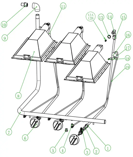
# | Our Item # | Description | QTY |
| 1 | 351140057 | CONNECTING NUT | 3 |
| 2 | 351140170 | ADAPTER | 3 |
| 3 | 351220059 | GAS VALVE | 3 |
| 4 | 351220028 | NG/LPG REGULATING VALVE | 3 |
| 5 | 351200620 | SCREW (TEST PLUG) | 2 |
| 6 | 351110280 | KNOB | 3 |
| 351110495 | DIAL INSERT | 3 | |
| 7 | 351180679 | GAS INLET PIPE | 1 |
| 8 | 35134008008 | BURNER ASSEMBLY | 3 |
| 9 | 351060026 | ELBOW | 1 |
| 10 | 351140044 | 1/2 COPPER CONNECTOR (GAS INLET PIPE) | 1 |
| 11 | 35134008055 | CONNECTING PIPE (BURNER) | 3 |
| 12A | 351ORIFICE59 | ORIFICE #59 – LP | 3 |
| 12B | 351ORIFICE52 | ORIFICE #52 – NAT | 3 |
| 13 | 351140058 | FLAT NUT | 3 |
| 14 | 351150100 | CONNECTOR (ORIFICE) | 3 |
| 15 | 351140025 | NUT | 3 |
| 16 | 35134014037 | PILOT BRACKET | 3 |
| 17 | 35134014038 | PILOT BRACKET SHROUDING | 3 |
| 18 | 351130019 | PILOT | 3 |
| 19 | 35134014023 | GAS INLET PIPE (PILOT) | 3 |
 https://www.cookingperformancegroup.com


