![]() USER MANUAL
USER MANUAL
Gas Salamander Broiler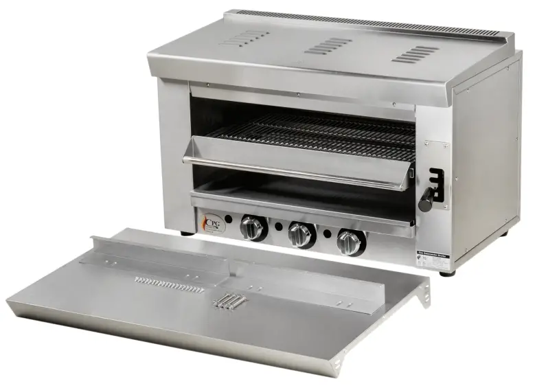
![]()
MODELS: 351S36SBL36K, 351S36SBL60K, 351S36SBLWK, 351S36SBN36K, 351S36SBN60K, 351S36SBNWK
Congratulations on your purchase of Cooking Performance Group commercial cooking equipment! At Cooking Performance Group, we take pride in the design, innovation, and quality of our products. When used as intended and with proper care and maintenance, you will experience years of reliable operation from your Cooking Performance Group equipment. To ensure optimal performance, we have outlined the following instructions and guidelines in this manual carefully for your review.
FEATURES AND SPECIFICATIONS
- Stainless steel body with a non-stick, enamel grill surface, that’s easy to clean
- Adjustable broiler rack can be raised or lowered
- (3) 12,000 BTU burners with independent controls allow for adjustable and even heating
| Model | 351 S36SB (L/N) 36K | 4 351 S36SB (L/N) 60K | 351 S36SB (L/N) WK | |
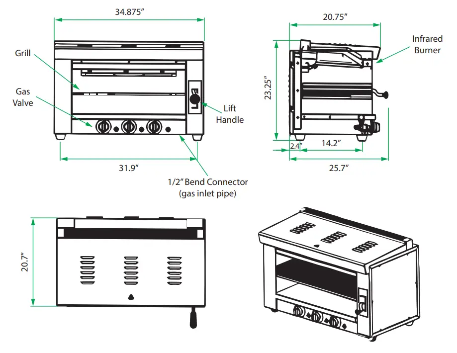
| Dimensions (in) | 34.875″W x 20.75″D x 23.25″H | 34.875″W x 20.75″D x 23.25″H | 34.875″W x 20.75″D x 23.25″H | |
| Mounting Type | 36″ Range Mount | 60″ Range Mount | Wall Mount | |
| Power | 36,000 BTU | 36,000 BTU | 36,000 BTU | |
| Pressure | LP | 10″WC | 10″WC | 10″WC |
| NG | 4″WC | 4″WC | 4″WC | |
| Orifice Size | LP | #59 | #59 | #59 |
| NG | #52 | #52 | #52 | |
| Gas Inlet Size | 1/2″ Rear Connection | 1/2″ Rear Connection | 1/2″ Rear Connection | |
| Salamander Weight | 155 lbs. | 155 lbs. | 155 lbs. | |
SAFETY PRECAUTIONS
CAUTION: Potential hazard or unsafe practice could result in minor or moderate injury or product or property damage.
NOTICE:
- Local codes regarding installation vary greatly from one area to another. The National Fire Protection Association, Inc., states in its NFPA96 latest edition that local codes are “Authority Having Jurisdiction” when it comes to the requirement for installation of equipment. Therefore, installation should comply with all local codes.
- This product is intended for commercial use only. Not for residential use.
WARNING:
- Do not store or use gasoline or other flammable vapors and liquids in the vicinity of this or any other appliance.
- Improper installation, adjustment, alteration, service or maintenance could lead to property damage, injury or death. Read the installation, operating and maintenance instructions thoroughly before installing or servicing CPG equipment. This manual must be retained for future reference.
- Instructions must be posted in a prominent location. All safety precautions must be taken in the event the user smells gas. Safety information can be obtained from your local gas supplier.
- An authorized service agency should handle all maintenance and repair. Prior to conducting any maintenance or repair work contact your authorized service representative.
GAS PRESSURE:
The appliance and its individual shutoff valve (to be supplied by the user) must be disconnected from the gas supply piping system during any pressure testing of that system at test pressures in excess of 1/2 PSI (3.45 kPa). The appliance must be isolated from the gas supply piping system by closing its individual manual shut-off valve during any pressure testing of the gas supply piping system at test pressures equal to or less than 1/2 PSI (3.45 kPa).
lit
SERIAL PLATE
NOTE: The serial plate is located on the front of the unit. 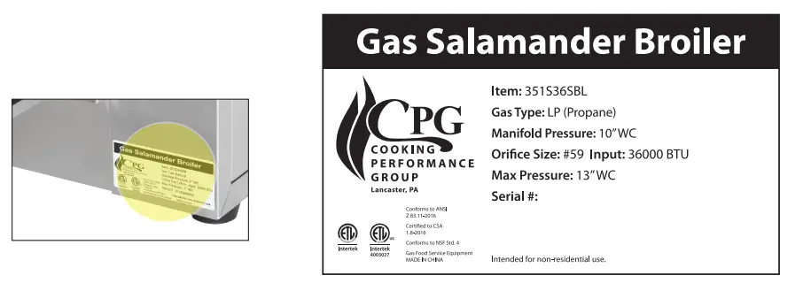
PRODUCT OVERVIEW
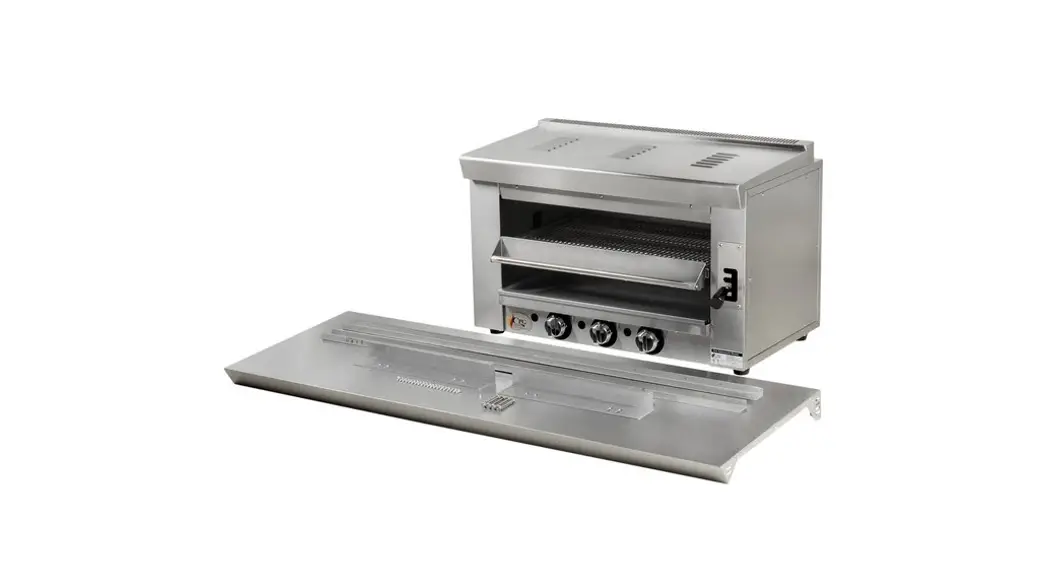
The CPG 351S36SB 36” gas salamander allows you to quickly and easily brown the top of casseroles, melt cheese, toast sandwiches, or even nish steaks and other meats! It is equipped with a gas-red 36,000 BTU atmospheric infrared burner with an adjustable gas valve and a continuous pilot for instant ignition.
The salamander features a sleek stainless steel front and sides, making it both durable and easy to clean! A full-width, large-capacity broiler pan can also be removed for convenient cleaning.
The salamander can be operated on an equipment stand, mounted to the wall or select Cooking Performance Group ranges using the appropriate mounting kit (sold separately).
SALAMANDER BROILER
INSTALLATION INSTRUCTIONS
THESE UNITS ARE SUITABLE FOR INSTALLATION ON NON-COMBUSTIBLE SURFACES ONLY. DO NOT INSTALL NEAR ANY COMBUSTIBLE SURFACES.
Combustible Clearance Requirements:4″ sides, 8″ back
IMMEDIATELY INSPECT FOR SHIPPING DAMAGE:
All containers should be examined for damage before and during unloading. The freight carrier has assumed responsibility for its safe transit and delivery. If equipment is received damaged, either apparent or concealed, a claim must be made with the delivering carrier.
Apparent damage or loss must be noted on the freight bill at the time of delivery. It must then be signed by the carrier representative (ie: driver). If this is not done, the carrier may refuse the claim. The carrier can supply the necessary forms.
Concealed damage or loss if not apparent until after the equipment is uncrated, a request for inspection must be made to the carrier upon opening the container. The carrier should arrange an inspection. Be certain to hold all contents and packaging material.
Installation and service should be performed by an authorized service agency. If you have questions concerning the installation, operation, maintenance or service of your equipment, visit CPG’s website at www.CookingPerformanceGroup.com.
Make sure that the surface where you plan to locate the step-up range/hot plate is capable of supporting its weight along with any accessories. Adequate clearance should be provided for proper operation and servicing. Level the step-up range/hot plate once you’ve uncrated it in your facility using the adjustable feet.
Proper ventilation is crucial to safe and optimum performance. Ensure that the oven is installed underneath a ventilation hood according to all applicable local and national codes. Keep adequate clearance for air openings into the combustion chamber.
PRECAUTIONS & RECOMMENDATIONS
TRANSPORTATION AND STORAGE
The unit should be handled carefully during transportation. Do not place the unit upside down. The packaged unit should be stored in a ventilated area without corrosive gas.
STARTUP
INSTALLATION
- Before installation, remove the outer plastic films.
- After receipt of the product, check that the unit is not damaged. Ensure that the lift mechanism is able to move up and down, the enameled layer of the grill hasn’t come off, and the unit is not rusted.
- Users can order a mounting rack/bracket. The mounting rack/bracket is optional for mounting to the wall or a compatible CPG range. Mounting must be done using a CPG kit specified at the time of order.
- Installation should be done by an authorized technician.
- Unit connection shall comply with provisions in gas safety, installation and operation.
- The unit is only applicable to a low-pressure gas regulating valve. It may cause property loss or safety accidents if a high or medium pressure regulating valve is used.
- The unit should keep a minimum clearance of 4” away from combustible objects (e.g. walls, windows, etc) on both sides, and 8” at its back. For use only on non-combustible floors.
- The unit should be installed under a vent hood in compliance with all applicable regulations.
- After installation, keep the appliance stable and level and do not tilt or sway during operation.
- If the pressure of the gas pipeline is 10% higher or lower than the rated pressure the unit requires, a regulator should be installed to ensure it reaches the rated value.
- After connecting the unit to the gas system, check for leaks at joints and pipe fittings using soapy water.
WARNINGS
- Installation and maintenance should be done by an authorized technician.
- Do not use gas that is not applicable to the unit or a high-pressure or medium-pressure regulating valve.
- The unit should be turned off when not in use or when left unattended.
- This product is a commercial machine that needs to be operated by trained personnel. The unit is not intended for residential use and such applications will void the warranty.
- Do not dismantle or self-modify the appliance.
- Do not touch the appliance directly during or after operation to prevent injury.
- The stainless steel surfaces should be cleaned appropriately and regularly.
MOUNTING INSTRUCTIONS
| Item | Photo | Measurement |
| Bolt A | 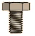 | M8 x 24 |
| Bolt B | 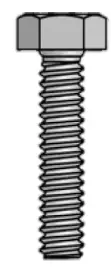 | M8 x 60 |
| Screw C | 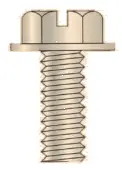 | 4-15 |
| Spring Washer |  | |
| Flat Washer |  |
STACKING 36” WIDE RANGE 
- Remove A _ bolts (x4), flat washers (x4), and spring washers (x4) from the backside of the backsplash. Keep flat washers (x2), and spring _ bolts (x4), flat washers (x2), washers (x2) for step 15. Discard A and spring washers (x2).
| ||
| 2. Remove and discard top shelf from backsplash. | 3. Remove C screws (x6) from the backside of the backsplash and remove C screws (x4) from the backside of support brackets. Keep C screws (x10) for steps 6 and 14. | 4. Remove original support brackets (x2) and backplate assembly from range. Discard original support brackets (x2). |
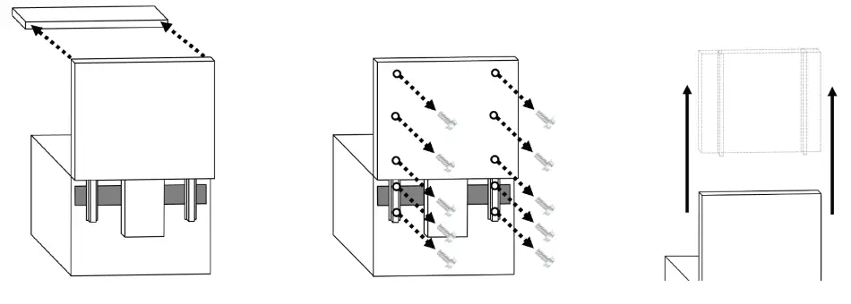
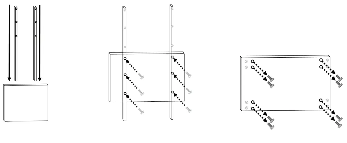 | ||
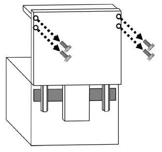
| 5. Insert new support brackets (x2) into U-shaped brackets that original support brackets were removed from. | 5. Insert new support brackets (x2) into U-shaped brackets that original support brackets were removed from. | 7. Remove A (x8), and spring washers (x8) from _ bolts (x8), flat washers back of salamander (specified in below diagram). Keep A bolts (x4), flat washers (x4), and spring washers (x4) for step 8. |
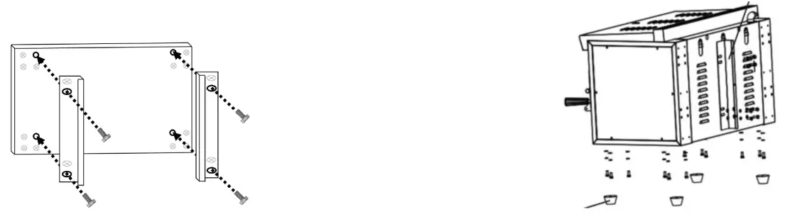 | ||
| 8. Attach L-shaped brackets (x2) to backside of the salamander using the A washers (x4), and spring washers (x4). _ bolts (x4), flat | 9. Before installation of the salamander, remove the outer plastic film | 10. Remove and discard rubber feet from salamander (x4). |
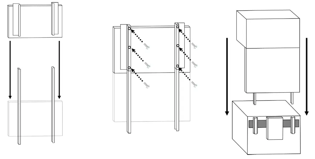 | ||
| 11. Lift salamander, and place into backsplash assembly. | 12. Secure support brackets and backplate assembly to the back of salamander assembly using C screws (x6). | 13. Lift salamander and back plate assembly onto range. |
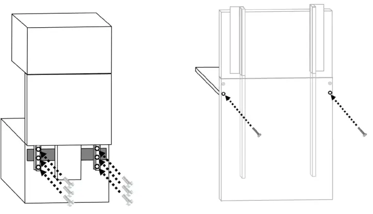 | |
| 13. Lift salamander and back plate assembly onto the range. | 15. Attach heat shelf to backsplash using B washers (x2). _ bolts (x2), flat washers (x2), and spring |
60” WIDE RANGE
- Select a side to mount the salamander to the range. It cannot be mounted in the center.
- Follow the same procedure as the 36″ range as listed above.
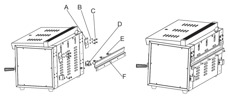
WALL MOUNT
- Secure top hanger plate (A) on salamander with spring washers (B) & screws (C).
- Secure bottom hanger plate (F) horizontally on wall with anchor bolts (E).
- Secure stand off (D) on salamander with spring washers (B) & screws (C).
- Put top hanger plate (A) on the bottom hanger plate (F) and tighten.
WORKING INSTRUCTIONS & OPERATIONAL FLOW
LIGHTING INSTRUCTIONS
- To light the unit, ensure that all the valves of the gas pipeline have been switched on.
- Arrange the drip pan, baking pan and broiler rack at appropriate places.
- Turn all knobs to the “OFF” position.
- Hold an ignition source (match) at the pilot. When the flame is established, remove the ignition source.
- Turn the burner knobs to “ON”. If the burner does not ignite, promptly open the pilot valve more. If the pilot flame appears larger than necessary, turn it down and reset burner ignition.
- Pull out the baking frame and place the food onto the rack.
- If the unit cannot be operated as explained, please contact Cooking Performance Group.
- The gas control knobs control the gas flow of every burner. The temperature can be increased by rotating the knobs counter-clockwise.
- Please be careful when operating the device to avoid burnings.
CLEANING & MAINTENANCE
- Pull out the rack assembly and detach the rack from the frame. Clean them separately before re-installing. Care should be taken during cleaning to prevent the enameled grill from being damaged.
- Remove the drip pan for cleaning.
- Wipe the chamber clean.
- Wash the unit with a wet cloth and soapy water solution or detergent solution as long as such solutions do not contain any acidic or alkaline substances. Wipe with clean water and then dry with a clean cloth. Do not use steel wool or brushes which may cause rust to form.
- Do not wash the unit with a water jet or hose. Water may penetrate inside the unit and damage the electric components.
- Cut off the gas supply when the unit is not in use.
- If you are not going to use the unit for a long period of time, clean the surface with a cloth and store it in a well-ventilated area.
- It is advised to carry out a complete inspection of the device at least once a year by professional personnel.
TROUBLESHOOTING
| Symptoms | Causes | Solutions |
| The pilot flame cannot be lit. | 1.Plug or plug cord of igniter is damaged. 2.Pressure in the gas pipeline is too low. 3.The pilot nozzle is blocked. 4.Thermocouple connection is loose. 5.The thermocouple is defective. 6.The gas control valve is defective. | 1.Replace relevant fittings. 2.Regulate the reducing valve or contact the gas supplier. 3.Unblock the nozzle. 4.Tighten the thermocouple. 5.Replace the thermocouple. 6.Repair or replace the gas control valve. |
| The pilot flame is on but the main burner cannot be lit. | 1.Pressure in the gas pipeline is too low. 2.Main nozzle is blocked. 3.The gas control valve is defective. | 1.Regulate the reducing valve or contact the gas supplier. 2.Unblock the nozzle. 3. Repair or replace the gas control valve. |
| There is a light-back sound when turning off the gas supply. | 1. Nozzle diameter does not match with the gas supply. 2.The supply pressure is too low. 3. Flow within the connected pipe is too low. | 1.Regulate the nozzle diameter. 2.Regulate the reducing valve or contact the gas supplier. 3.Increase the permitted flow. |
| Unit has red flame and black smoke. | 1.Nozzle diameter does not match with the gas supply. 2.Low gas supply. 3.Gas ingredients are volatile in gas peak period. | 1.Regulate the nozzle diameter. 2.Increase the gas supply. 3.Decrease the gas flow. Increase it after the peak. |
The issues mentioned above are for reference. If any failure occurs, please stop using and contact Cooking Performance Group. Safety is first and maintenance should be done after shutting down the power supply and gas supply.
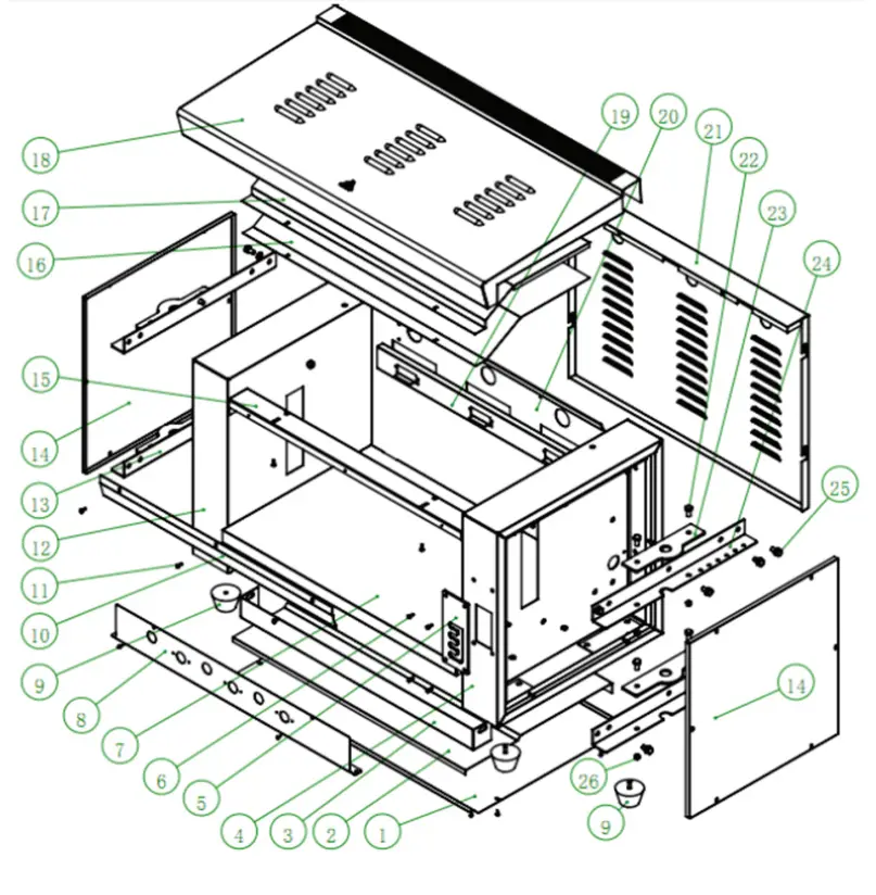
PARTS DIAGRAM -WHOLE ASSEMBLY PARTS LIST -WHOLE ASSEMBLY
 PARTS LIST -WHOLE ASSEMBLY
| # | Our Item # | Description | QTY |
| 1 | 35134014034 | BASEBOARD | 1 |
| 2 | 35134014036 | COTTON INSULATION PLATE | 1 |
| 3 | 35134014039 | BOTTOM BEAM | 1 |
| 4 | 35134014003 | SIDE PANEL (RIGHT) | 1 |
| 5 | 35134014013 | GEAR PLATE | 1 |
| 6 | 351212221 | BOLT | 4 |
| 7 | 35134014001 | BASEBOARD (BOX) | 1 |
| 8 | 35134014040 | FRONT PANEL | 1 |
| 9 | 351090026 | RUBBER FOOT | 4 |
| 10 | 35134014016 | BAFFLE | 1 |
| 11 | 351210277 | SCREW | – |
| 12 | 35134014004 | SIDE PANEL (LEFT) | 1 |
| 13 | 35134014014 | REINFORCING PLATE (LEFT) | 2 |
| 14 | 35134008012 | SIDE SEALING PLATE (LEFT & RIGHT) | 2 |
| 15 | 35134008007 | FRONT BEAM | 1 |
| 16 | 35134008010 | TOP PANEL (CHAMBER) | 1 |
| 17 | 35134008014 | COTTON PRESSING PLATE (TOP) | 1 |
| 18 | 35134008009 | TOP COVER PLATE | 1 |
| 19 | 35134008039 | SUPPORTING PLATE (PROBE) | 1 |
| 20 | 35134014002 | BACK PANEL (CHAMBER) | 1 |
| 21 | 35134014006 | SIDE SEALING PLATE (BACK) | 1 |
| 22 | 351212427 | BOLT | 8 |
| 23 | 35134008024 | SHAFT PLATE | 4 |
| 24 | 35134014015 | REINFORCING PLATE (RIGHT) | 2 |
| 25 | 351214271 | BOLT | 12 |
| 26 | 351213138 | NUT | – |
| 27* | 35134014021 | MOUNTING KIT -WALL | – |
| 28* | 35128059015 | MOUNTING KIT- S60, S60G24 RANGE | – |
| 29* | 35128051052 | MOUNTING KIT – S36 RANGE | – |
PARTS DIAGRAM – LIFT ASSEMBLY 
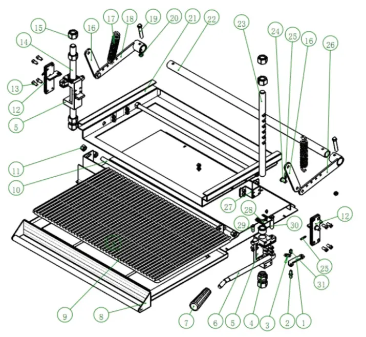
PARTS LIST- LIFT ASSEMBLY
| # | Our Item # | Description | QTY |
| 1 | 351201261 | CLAW PLATE | 1 |
| 2 | 351201273 | STOP PIN | 1 |
| 3 | 351080087 | LOCKING TENSION SPRING | 1 |
| 4 | 351201265 | SLIDE BUSHING | 1 |
| 5 | 351201259 | SLIDE BUSHING BASE (RIGHT) | 2 |
| 6 | 351201262 | HANDLE STEM | 1 |
| 7 | 351070161 | HANDLE COVER | 1 |
| 8 | 35134014005 | RACK SUPPORTING ASSEMBLY | 1 |
| 9 | 351110668 | RACK | 1 |
| 10 | 351201276 | SCREW | 1 |
| 11 | 351210038 | NUT | 8 |
| 12 | 35134014001 | COVER PLATE ASSEMBLY (RIGHT SLIDE BUSHING) | 2 |
| 13 | 351212221 | SCREW | 24 |
| 14 | 351201264 | SLIDE SHAFT (LEFT) | 1 |
| 15 | 351210057 | NUT | 8 |
| 16 | 35134014027 | CONNECTING ROD | 2 |
| 17 | 351080088 | LIFTING TENSION SPRING | 2 |
| 18 | 35134014004 | ARM ASSEMBLY (LEFT) | 1 |
| 19 | 351214197 | BOLT | 2 |
| 20 | 351213139 | NUT | 4 |
| 21 | 35134014007 | LIFTING CHASSIS | 1 |
| 22 | 351040286 | CONNECTING SHAFT | 1 |
| 23 | 351201263 | SLIDE SHAFT (RIGHT) | 1 |
| 24 | 351201274 | SHAFT PIN | 2 |
| 25 | 351214205 | COTTER PIN | 4 |
| 26 | 35134014003 | ARM ASSEMBLY (RIGHT) | 1 |
| 27 | 35134014008 | CONNECTING PLATE (CHASSIS) | 1 |
| 28 | 35134014031 | PRESSING PLATE (SLIDE BUSHING) | 2 |
| 29 | 351210295 | SCREW | 1 |
| 30 | 351201266 | SHAFT PIN (OPERATING LEVER) | 1 |
| 31 | 351213137 | NUT | 3 |
PARTS DIAGRAM – BURNER ASSEMBLY 
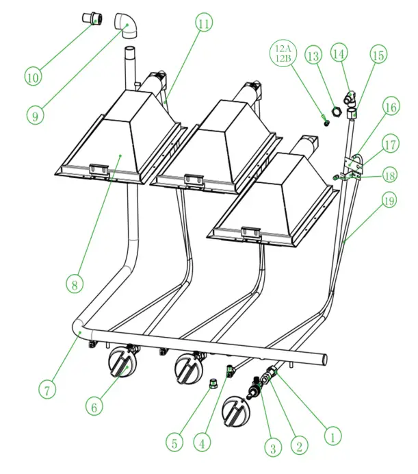
PARTS LIST – BURNER ASSEMBLY
| # | Our Item # | Description | QTY |
| 1 | 351140057 | CONNECTING NUT | 3 |
| 2 | 351140170 | ADAPTER | 3 |
| 3 | 351220059 | GAS VALVE | 3 |
| 4 | 351220028 | NG/LPG REGULATING VALVE | 3 |
| 5 | 351200620 | SCREW (TEST PLUG) | 2 |
| 6 | 351110280 | KNOB | 3 |
| 351110495 | DIAL INSERT | 3 | |
| 7 | 351180679 | GAS INLET PIPE | 1 |
| 8 | 35134008008 | BURNER ASSEMBLY | 3 |
| 9 | 351060026 | ELBOW | 1 |
| 10 | 351140044 | 1/2 COPPER CONNECTOR (GAS INLET PIPE) | 1 |
| 11 | 35134008055 | CONNECTING PIPE (BURNER) | 3 |
| 12A | 3510RIFICE59 | ORIFICE #59 – LP | 3 |
| 12B | 3510RIFICE52 | ORIFICE #52- NAT | 3 |
| 13 | 351140058 | FLAT NUT | 3 |
| 14 | 351150100 | CONNECTOR (ORIFICE) | 3 |
| 15 | 351140025 | NUT | 3 |
| 16 | 35134014037 | PILOT BRACKET | 3 |
| 17 | 35134014038 | PILOT BRACKET SHROUDING | 3 |
| 18 | 351130019 | PILOT | 3 |
| 19 | 35134014023 | GAS INLET PIPE (PILOT) | 3 |
NOTES
www.CookingPerformanceGroup.com


