HUAWEI UPS2000-G-6KRTLL Highly Efficient Power Protection Solution
Overview
| UPS Model | Represented By | Weight | Dimensions (H x W x D) |
| UPS2000-G-6KRTLL | 6 kVA | 15 kg | 131 mm x 438 mm x 480 mm |
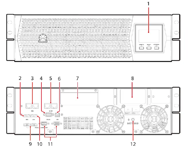
- LCD
- MBS port
- BMS ports
- RS232 communications port
- RS485 communications ports (connect to northbound devices)
- USB port
- AC input and output terminals (behind the cover)
- Battery input terminal (behind the cover)
- Parallel current equalization ports
- EPO port
- Parallel communications ports
- Battery PE terminal
NOTE
The RS485 ports support only the Modbus RTU protocol. For details, see the Modbus development guide and Modbus user manual
Installing a UPS
NOTICE
- Carefully read the UPS2000-G-6KRTLL User Manual prior to installation to get familiar with product information and safety precautions.
- Use fully insulated tools during installation and operation.
- Only engineers certified by the manufacturer or its agent are allowed to install, commission, and maintain the UPS. Otherwise, personal injury or equipment damage may occur, and the UPS faults caused are beyond the warranty scope of Huawei.
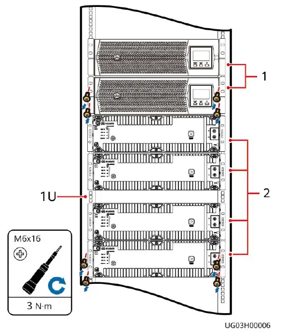
Scenario Rack-Mounting the UPS2000-G
- Reserve a space of 1 U in the middle of four batteries for routing battery power cables.
- Reserve a space of 5 cm between the battery communications port and the cabinet for installing a communications cable.
- Reserve a space of 44 mm between the battery edge and the rack edge for installing battery power cables.
- In rack-mounted installation scenarios, the front panels of the UPS and lithium batteries are not on the same plane.
- The guide rails for the UPS2000-G-6KRTLL are 592.37 mm to 807.37 mm long, 30 mm wide, and 87 mm high. The guide rails are scalable and support Huawei M-shaped cabinets.
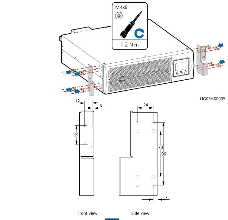
- Install mounting brackets on UPS

- Install devices from bottom to top, as shown in the

- Install mounting brackets on UPS
Installing Cables
WARNING
- Connect UPS AC input and output power cables in the same phase sequence. Connect battery terminals correctly.
- Before connecting cables to the UPS, ensure that the input, output, and battery circuit breakers are OFF to prevent operations with power applied.
Installing Power Cables
Scenario 1 Installing Cables for a Single UPS
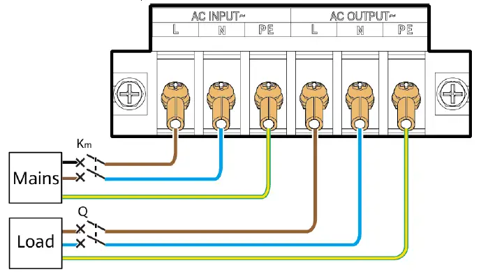
- Install AC input and output power cables.
Wiring Terminal Input (AC INPUT) Output (AC OUTPUT) External Circuit Breaker 32 A Earth Leakage Circuit Breaker 100 mA – Cable Cross-sectional Area 6 mm² Terminal Type OT-6 mm2-M5 terminal Torque for Tightening Bolts 2 N·m 
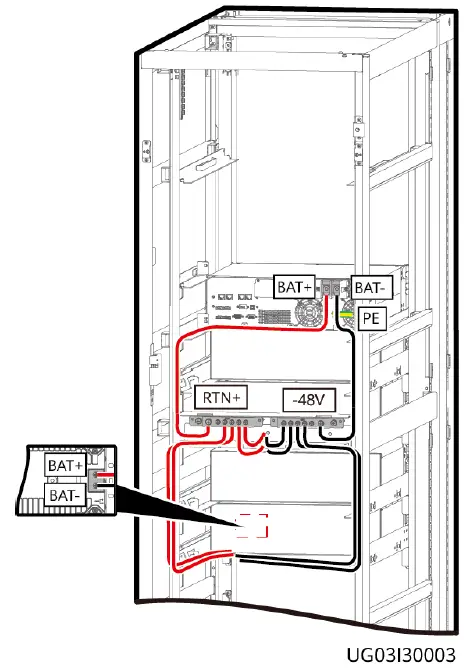
- Install battery cables.
NOTE
- The UPS2000-G-6KRTLL needs to connect to external lithium batteries ESM-48100B1 or ESM-48150B1. Each UPS supports a maximum of 16 batteries connected in parallel. This document uses four lithium batteries connected in parallel as an example.
- When lithium batteries are connected, it is recommended that a DC circuit breaker (150 A 80 V DC circuit breaker for the 6 kVA UPS) be installed between the lithium batteries and the UPS.
- Before connecting cables to the UPS, ensure that the battery circuit breakers are OFF to prevent operations with power applied.
- If the UPS shares a battery string, the PE bar and battery busbar are configured.
Recommended power cable specifications
| Wiring Terminal | Battery (BATT. 48VDC) |
| External Circuit Breaker | 125 A (type D) |
| Cable Cross-sectional Area | 25 mm² |
| Terminal Type | OT-25 mm2-M8 terminal |
| Torque for Tightening Bolts | 7 N·m |
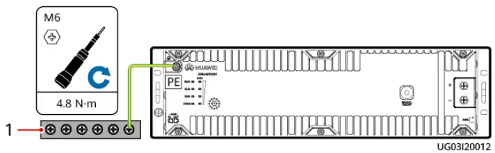
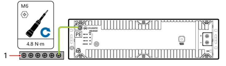
Installing the battery PE cable
Installing battery cables (rack-mounted, front view)
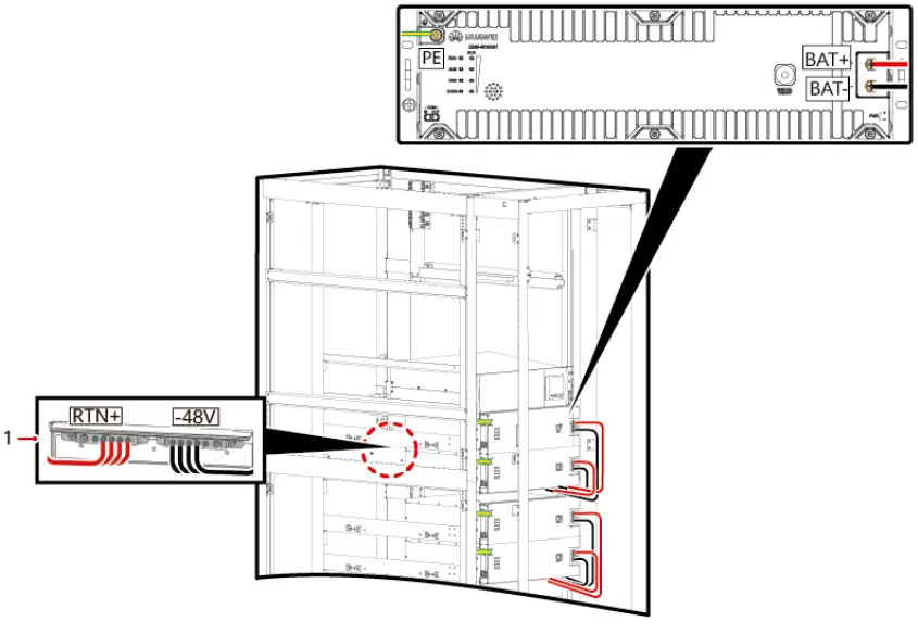
Installing battery cables (rack-mounted, rear view)
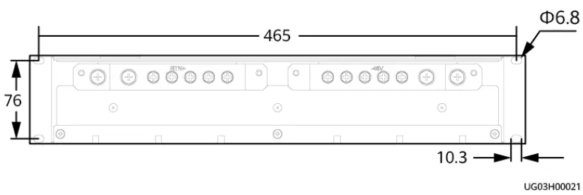
NOTE
Busbar mounting hole dimensions (unit: mm)
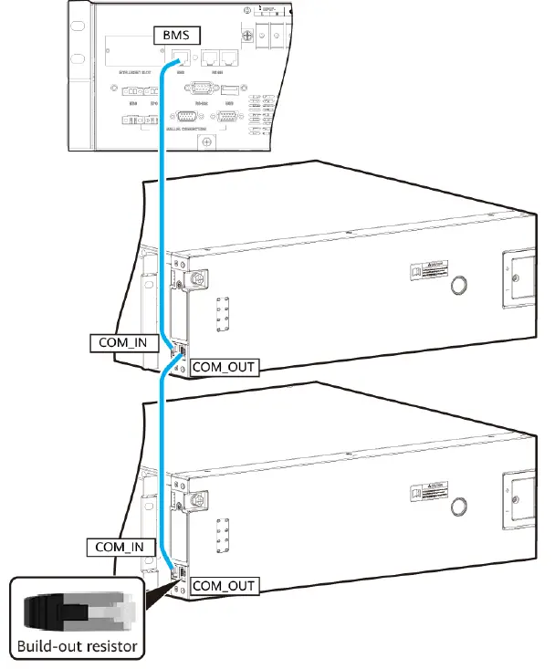
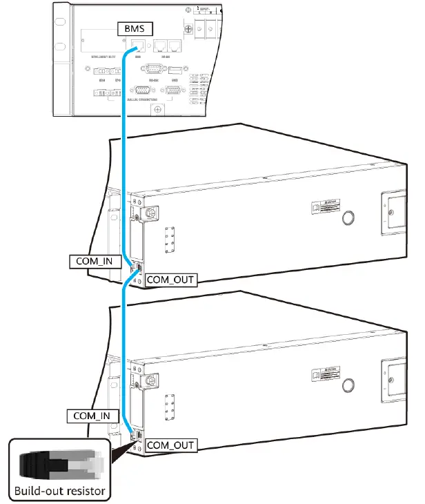
Install battery communications cables.
NOTICE
Install a build-out resistor at the COM_OUT port on the last lithium battery
Scenario 2 Installing Cables for Parallel UPSs
- Before parallel running, ensure that all output circuit breakers for each UPS are ON. Otherwise, a UPS fault (error code #72) will occur.
- Batteries must be connected for parallel running.
- Install AC input and output power cables
NOTE
Two UPSs connected in parallel are used as an example
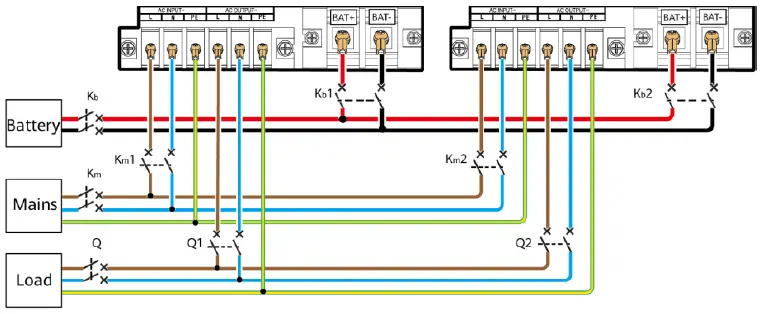
- Install battery cables.
Installing the battery PE cable (1) Ground bar Installing battery cables (rack-mounted, front view)
 (1) Busbar Installing battery cables (rack-mounted, rear view)
- Install battery communications cables.
NOTICE
Install a build-out resistor at the COM_OUT port on the last lithium battery
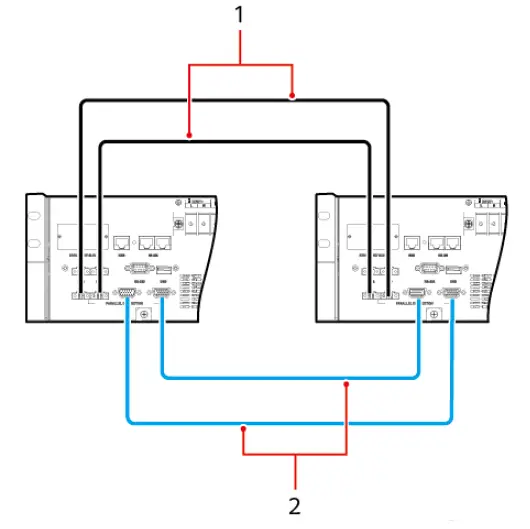
- Install parallel communications cables and parallel current equalization cables. In this example, two UPSs are connected in parallel

- Parallel current equalization cables
- Parallel communications cables
 (1) Ground bar Installing battery cables (rack-mounted, front view)
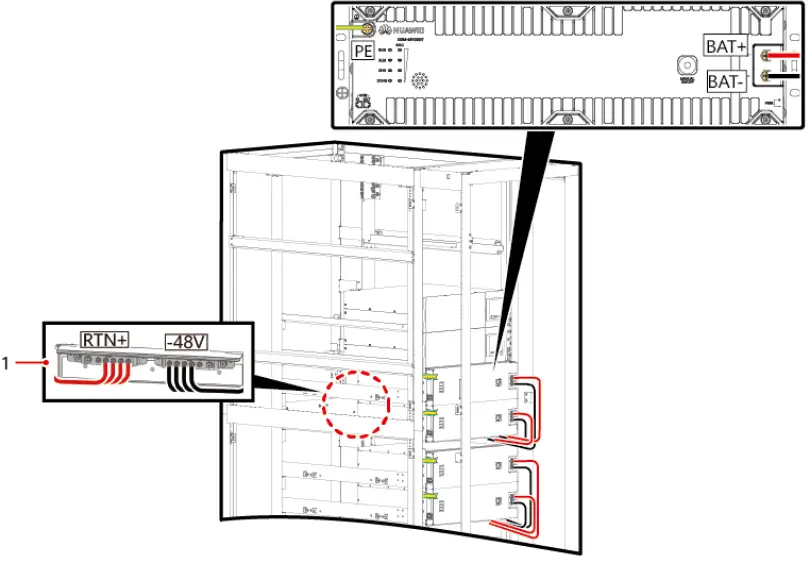 (1) Busbar Installing battery cables (rack-mounted, rear view)
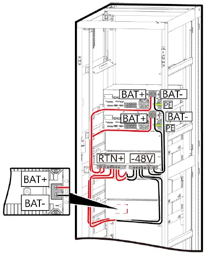
Installing Communications Cables
NOTE
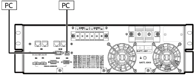
- The USB channel supports a serial data communications protocol between the UPS and a PC.
- If you connect a DB9 connector to the RS232 port, the UPS can exchange data with the PC over serial communication.
- You can use only either USB or RS232.
Verifying the Installation
| No. | Item | Expected Result |
| 1 | Cable routing | Cables are routed properly according to engineering requirements. |
| 2 | Cable connection | All cables are connected securely and correctly, and they are free of damage. Bolts are tightened to specified torque using a torque wrench. |
| 3 | Cable connection to USB, network, and other ports | Signal cables to USB, network, and other ports are connected securely and correctly. |
| 4 | Cable labels | Labels are neatly attached to both ends of each cable, and the information on the labels is concise and legible. |
| 5 | Ground cable connection | The UPS ground cable is securely connected to the equipment room ground bar. Use a multimeter to measure the resistance between the UPS ground cable and the equipment room ground bar. The resistance is less than 0.1 ohm. |
| 6 | Spacing between cable ties | Distances between cable ties are the same, and no burr exists. |
| 7 | Operating environment | The inside and outside of the cabinet are free from conductive dust or other sundries. |
Operations
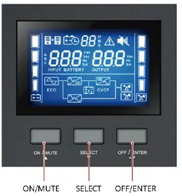
Setting Key UPS Parameters
- Switch on the external battery circuit breaker (if any).
- Switch on the external AC input circuit breaker (if any) of the UPS. The UPS transfers to the standby mode.
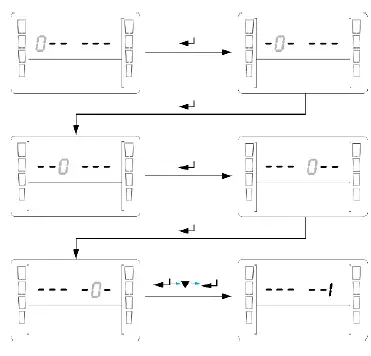
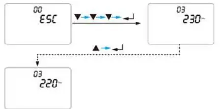
- Press and hold SELECT for 1s on a non-setting screen to access the login screen for parameter settings. The initial password is 000001. Enter the correct password to enter the UPS setting mode.

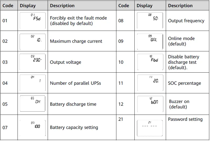
- Set the output voltage to 220 V AC or other values based on site requirements. The value can be 220 V AC, 230 V AC (default), or 240 V AC.

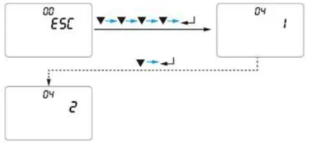
- In a parallel system, set the number of parallel UPSs to 2 or other values on each UPS based on site requirements. The value is 1 by default and range from 1 to 4.

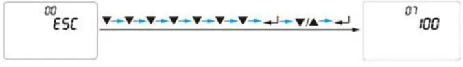
- Set the battery capacity to 100 Ah or other values based on site requirements. The value is 100 Ah by default and can range from 50 Ah to 2400 Ah. The value increases by 50 Ah each time you press the SELECT button

- Press ON/MUTE+SELECT to return to the standby screen.
NOTE
For details about parameter settings, see the UPS2000-G-6KRTLL User Manual
Common Settings
- Shut down loads.
- Press and hold down OFF/ENTER for more than 5s. Release the button when you hear the buzzer buzzing. The UPS shuts down the inverter and transfers to bypass mode. If mains parameters are inconsistent with bypass parameters, the UPS transfers to standby mode.
- Switch off the UPS AC input circuit breaker (on the power distribution cabinet or external switch) and output circuit breaker (if any) based on site requirements.
- Switch off the external battery circuit breaker (if any), or disconnect battery power cables (if there is no external battery circuit breaker).
Alarm Handling
| Alarm ID | Alarm Name | Severity | Clearance Condition | Trigger Condition | Impact on the System | Suggestion |
| 01 | Fan | Minor | The fan | The fan | The current | • Possible cause: |
| blocked | automaticall | blockage | working status | The fan is | ||
| y recovers | signal is at | is not affected. | blocked. | |||
| from | low level | If | Measure: Check | |||
| blockage. | for 15s | overtemperature | the fan and | |||
| within 30s. | protection is | remove | ||||
| triggered, the | sundries. | |||||
| system may | • Possible cause: | |||||
| transfer to | The fan is faulty. | |||||
| bypass mode. | Measure: | |||||
| Replace the fan. | ||||||
| 02 | Overtem | Critical | Fan blocked: | Fan | The system | • Possible cause: |
| perature | The highest | blocked: | shuts down the | The | ||
| temperature | The highest | inverter and | temperature is | |||
| of internal | temperatur | transfers to | too high. | |||
| components | e of | bypass mode. | Measure: | |||
| is lower than | internal | Decrease the | ||||
| 65°C. Fan | component | ambient | ||||
| not blocked: | s exceeds | temperature or | ||||
| The highest | 80°C for | load. | ||||
| temperature | 100 ms. | • Possible cause: | ||||
| of internal | Fan not | The | ||||
| components | blocked: | temperature | ||||
| is lower than | The highest | sensor is faulty. | ||||
| 50°C. After | temperatur | Measure: Send | ||||
| the | e of | the device to the | ||||
| temperature | internal | maintenance | ||||
| is restored to | component | center. | ||||
| normal, the | s exceeds | |||||
| alarm can be | 90°C for | |||||
| automaticall | 100 ms. | |||||
| y cleared for | ||||||
| three times. | ||||||
| After that, | ||||||
| you need to | ||||||
| manually | ||||||
| clear the | ||||||
| alarm. |
| Alarm ID | Alarm Name | Severity | Clearance Condition | Trigger Condition | Impact on the System | Suggestion |
| 03 | High | Critical | The alarm is | The battery | The system | • Possible cause: The |
| battery | automatically | voltage is | shuts down | battery is faulty. | ||
| voltage | cleared when | greater than | the inverter | Measure: Replace | ||
| the battery | 60 V for 3s. | and transfers | the battery or | |||
| voltage is | to bypass | discharge the | ||||
| lower than | mode. | battery to a normal | ||||
| 58 V. | voltage. | |||||
| • Possible cause: The | ||||||
| sampling is faulty | ||||||
| due to | ||||||
| environmental | ||||||
| factors. | ||||||
| Measure: Send the | ||||||
| device to the | ||||||
| maintenance center. | ||||||
| 04 | Very | Minor | The battery | The battery | The system | • Possible cause: The |
| low | voltage is | voltage is | cannot supply | battery is faulty. | ||
| battery | higher than | lower than | power in | Measure: Replace | ||
| voltage | 42 V and the | 42 V. | battery mode. | the battery or | ||
| mains is | If this alarm | charge the battery | ||||
| connected | is generated | to a normal voltage. | ||||
| properly. | in battery | • Possible cause: The | ||||
| mode, the | sampling is faulty | |||||
| power output | due to | |||||
| will be | environmental | |||||
| disconnected. | factors. | |||||
| Measure: Send the | ||||||
| device to the | ||||||
| maintenance center. | ||||||
| 05 | Output | Critical | The alarm | The output | The system | Possible cause: The |
| short- | can be | voltage is | disconnects | load or cable is | ||
| circuit | automatically | lower than | the power | short-circuited. | ||
| cleared for | 50 V and the | output. | Measure: Locate | |||
| three times. | current is | and rectify the | ||||
| After that, | higher than | short-circuit fault. | ||||
| you need to | 20 A for | |||||
| manually | more than | |||||
| clear the | five cycles of | |||||
| alarm or | time. | |||||
| restart the | ||||||
| device. | ||||||
| 06 | High | Critical | You need to | The output | The system | • Possible cause: |
| output | manually | voltage | shuts down | Load energy | ||
| voltage | rectify the | exceeds the | the inverter | backfeed occurs. | ||
| fault or | rated | and transfers | Measure: Locate the | |||
| power off | voltage by | to bypass | load and remove it. | |||
| and restart | 20 V for 3s. | mode. | • Possible cause: The | |||
| the device. | circuit is faulty. | |||||
| Measure: Send the | ||||||
| device to the | ||||||
| maintenance center. | ||||||
| Alarm ID | Alarm Name | Severity | Clearance Condition | Trigger Condition | Impact on the System | Suggestion |
| 07 | Overloa | Critical | You need to | The output | The system | Possible cause: The |
| d | manually | overload | disconnects | load exceeds the UPS | ||
| rectify the | time | the power | capacity. | |||
| fault or | exceeds | output. | Measure: Reduce the | |||
| power off | the | load. | ||||
| and restart | specificatio | |||||
| the device. | n. | |||||
| 08 | High | Critical | When the | The bus | The system | • Possible cause: Power |
| bus | bus voltage | voltage is | shuts down | grid surge occurs. | ||
| voltage | is lower | greater | the inverter | Measure: Improve the | ||
| than 360 V, | than 450 V | and transfers | power grid quality. | |||
| the alarm | for 200 ms | to bypass | • Possible cause: The | |||
| can be | or greater | mode. | parallel cable is | |||
| automatical | than 470 V | disconnected when | ||||
| ly cleared | for 1 ms. | UPSs are connected in | ||||
| for two | parallel. | |||||
| times. After | Measure: Check that | |||||
| that, you | the parallel cable and | |||||
| need to | current equalization | |||||
| manually | cable are properly | |||||
| clear the | connected. | |||||
| fault or | • Possible cause: The | |||||
| power off | circuit is faulty. | |||||
| and restart | Measure: Send the | |||||
| the device. | device to the | |||||
| maintenance center. | ||||||
| 09 | Bus | Critical | You need to | The bus | The system | Possible cause: The |
| short- | manually | soft-start | cannot start | circuit is faulty. | ||
| circuit | rectify the | time | inverter | Measure: Send the | ||
| fault or | exceeds | output and | device to the | |||
| power off | 15s. | transfers to | maintenance center. | |||
| and restart | bypass mode. | |||||
| the device. | ||||||
| 12 | Manual | Minor | The open- | The | The system | Restore the open- |
| bypass | circuit | manual | transfers to | circuit status of the | ||
| activate | status of | bypass port | bypass mode. | manual bypass port. | ||
| d | the manual | is short- | ||||
| bypass is | circuited. | |||||
| restored. |
| Alarm ID | Alarm Name | Severity | Clearance Condition | Trigger Condition | Impact on the System | Suggestion |
| 13 | Phase | Minor | Phase | The inverter fails | The system | Possible cause: |
| lock | locking is | in phase locking | cannot start | The power grid | ||
| failure | successful | within 10s. | PFC or enter | frequency is | ||
| or the | normal | unstable. | ||||
| bypass is | mode. | |||||
| missing. | ||||||
| 17 | Bypass | Minor | The bypass | The bypass | • The system | • Check that the |
| abnorm | voltage or | voltage or | cannot | bypass | ||
| al | frequency | frequency is out | transfer to | connection is | ||
| recovers to | of the normal | bypass mode | normal. | |||
| the normal | range. | when a | • Check that the | |||
| range. | critical alarm | bypass voltage | ||||
| is generated. | and frequency are | |||||
| • In bypass | within their | |||||
| mode, the | normal ranges. | |||||
| power output | ||||||
| is | ||||||
| disconnected. | ||||||
| 18 | Low | Minor | The battery | Communication is | The battery | Possible cause: |
| lithium | voltage or | normal, but the | level is close | The battery | ||
| battery | SOC rises | SOC is lower than | to the cutoff | charge level is | ||
| level | above the | 20%. | threshold. If | low. | ||
| alarm | Communication is | there is no | Measure: Charge | |||
| threshold. | abnormal, and | mains input, | the battery. | |||
| the battery | the system | |||||
| voltage falls to | will shut | |||||
| 47 V DC. | down after | |||||
| working for a | ||||||
| period of | ||||||
| time. | ||||||
| 19 | Abnor | Minor | The mains | • The mains is | The system | Check whether |
| mal | voltage | disconnected or | cannot work | the mains voltage | ||
| mains | input | fails. | in normal | input is normal. If | ||
| voltage | recovers. | • The mains input | mode. If this | the circuit is | ||
| voltage harmonic | alarm is | faulty, send the | ||||
| exceeds 10% | generated in | device to the | ||||
| (square wave | normal | maintenance | ||||
| input is not | mode, the | center. | ||||
| supported). | system | |||||
| • The mains | transfers to | |||||
| frequency change | battery | |||||
| rate exceeds the | mode. | |||||
| phase lock rate | ||||||
| defined in the | ||||||
| specifications (2 | ||||||
| Hz/s for a single | ||||||
| UPS and 1 Hz/s | ||||||
| for a parallel | ||||||
| system). | ||||||
| Alarm ID | Alarm Name | Sever ity | Clearance Condition | Trigger Condition | Impact on the System | Suggestion |
| 20 | Lithium | Minor | The cell | • Charge high | The | Possible cause: The |
| battery | temperatur | temperature | internal | ambient temperature | ||
| high | e drops | protection: The | switch | of the lithium battery | ||
| tempera | below the | maximum cell | circuit of | is too high. There are | ||
| ture | protection | temperature is | the lithium | abnormal heat sources | ||
| protecti | threshold. | greater than | battery is | around the lithium | ||
| on | 60°C. | disconnect | battery. | |||
| • Discharge high | ed, and | Measure: If the lithium | ||||
| temperature | the battery | battery cannot be | ||||
| protection: The | cannot be | recovered due to | ||||
| maximum cell | charged or | protection against | ||||
| temperature is | discharged | abnormality, contact | ||||
| greater than | . | local Huawei | ||||
| 65°C. | engineers to rectify | |||||
| the fault. | ||||||
| 21 | Lithium | Minor | The cell | • Charge low | The | Possible cause: The |
| battery | temperatur | temperature | internal | ambient temperature | ||
| low | e rises | protection: The | switch | of the lithium battery | ||
| tempera | above the | minimum cell | circuit of | is too low. The heater | ||
| ture | protection | temperature is | the lithium | cannot work properly. | ||
| protecti | threshold. | less than 0°C. | battery is | Measure: If the lithium | ||
| on | • Discharge low | disconnect | battery cannot be | |||
| temperature | ed, and | recovered due to | ||||
| protection: The | the battery | protection against | ||||
| minimum cell | cannot be | abnormality, contact | ||||
| temperature is | charged or | local Huawei | ||||
| less than –20°C. | discharged | engineers to rectify | ||||
| . | the fault. | |||||
| 23 | Lithium | Minor | The cell or | The lithium | The | Possible cause: The |
| battery | battery | battery voltage is | internal | mains power has | ||
| low | string | less than 44 V. | switch | failed and not been | ||
| voltage | voltage | The minimum | circuit of | recovered for a long | ||
| protecti | rises above | cell voltage is | the lithium | time. The cell | ||
| on | the | less than 2.5 V. | battery is | consistency is | ||
| protection | disconnect | abnormal. The | ||||
| threshold. | ed, and | capacity attenuation is | ||||
| the battery | too fast or the internal | |||||
| cannot be | resistance is too large. | |||||
| charged or | Measure: If the lithium | |||||
| discharged | battery cannot be | |||||
| . | recovered due to | |||||
| protection against | ||||||
| abnormality, contact | ||||||
| local Huawei | ||||||
| engineers to rectify | ||||||
| the fault. |
| Alar m ID | Alarm Name | Severity | Clearance Condition | Trigger Condition | Impact on the System | Suggestion |
| 24 | Lithium | Minor | The battery | Discharge | The internal | Possible cause: The |
| battery | discharge | current ≥ 0.93 | switch circuit | UPS is overloaded. | ||
| overcur | current | times of the | of the lithium | The number of | ||
| rent | drops | current limit | battery is | working batteries is | ||
| protecti | below the | and Vbus ≤ | disconnected, | insufficient. | ||
| on | protection | 40 V for 15s | and the | Measure: Reduce the | ||
| threshold. | Discharge | battery | load. Add batteries. | |||
| current ≥ 0.98 | cannot be | |||||
| times of the | charged or | |||||
| current limit | discharged. | |||||
| and Vbus < | ||||||
| 17 V for 8s | ||||||
| 27 | Battery | Minor | The battery | Battery | The system | Measure: Turn off |
| dischar | discharge | discharge test | transfers to | the battery discharge | ||
| ge est | test is | is enabled | battery mode. | test mode switch. | ||
| functio | complete. | manually. | ||||
| n | ||||||
| enable | ||||||
| d | ||||||
| 28 | The | Minor | Set item 05 | The battery | The system | Check whether the |
| battery | battery | discharge | cannot supply | mains input is | ||
| dischar | discharge | time reaches | power in | normal. | ||
| ge time | time to 0 or | the preset | battery mode. | |||
| reaches | restart the | value. | If this alarm | |||
| the | inverter. | is generated | ||||
| maxim | in battery | |||||
| um. | mode, the | |||||
| power output | ||||||
| will be | ||||||
| disconnected. |
Huawei Technologies Co., Ltd.
Huawei Industrial Base, Bantian, Longgang Shenzhen 518129 People’s Republic of China www.huawei.com


