HUAWEI DTSU666-H Smart Power Sensor User Guide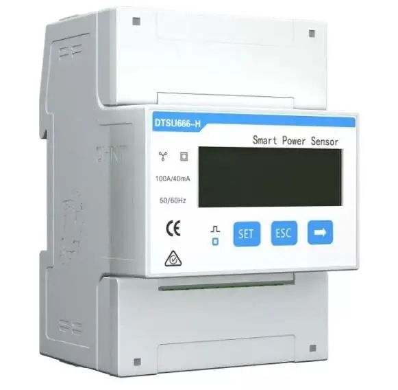
Overview
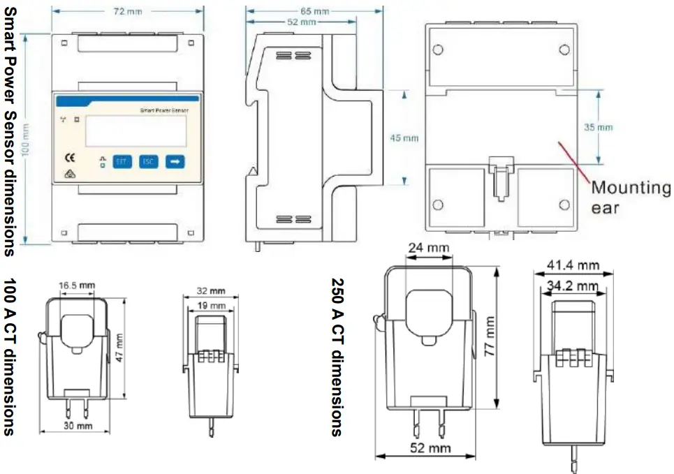
Models
- DTSU666-H: with three 100 A/40 mA CT
- DTSU666-H 250 A/50 mA: with three 250 A/50 mA CT

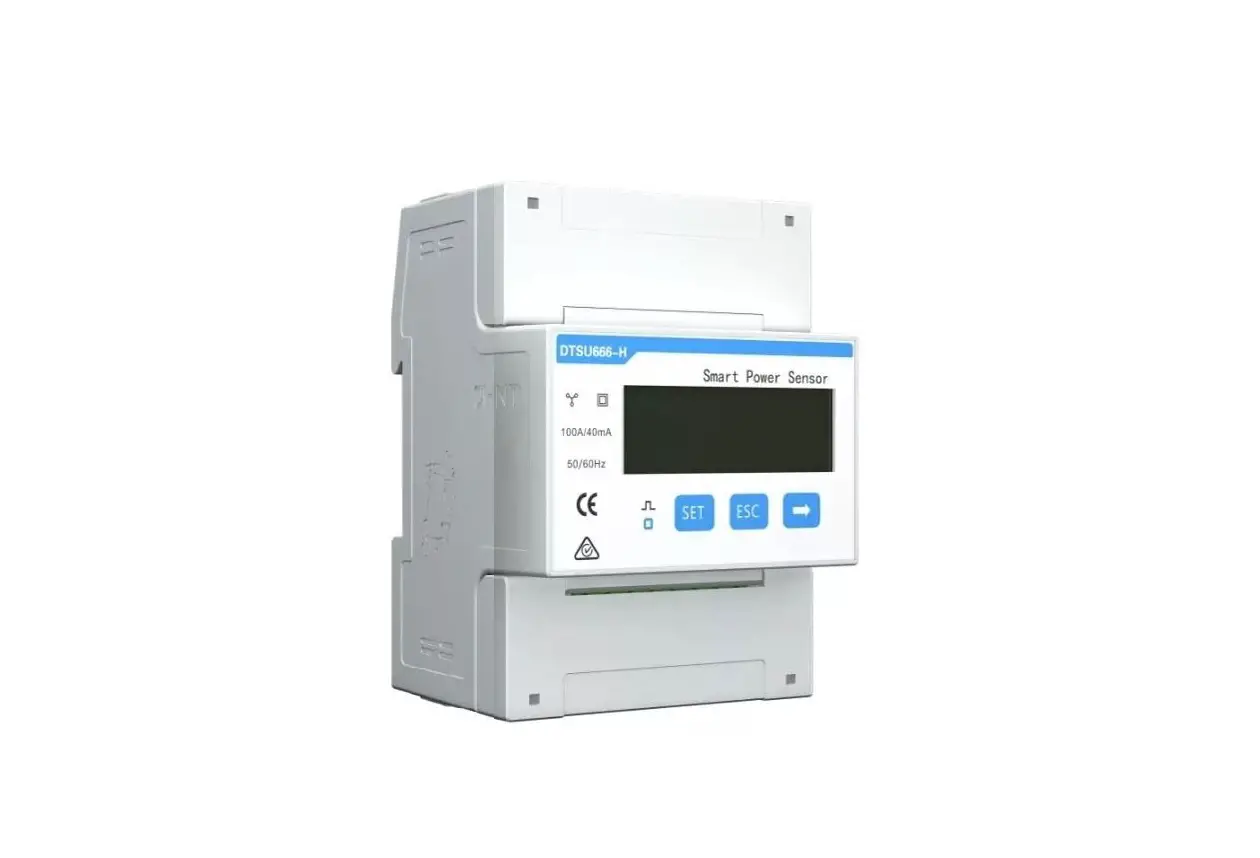
Appearance
Differences between DTSU666-H and DTSU666-H 250 A/50 mA:
- Parameters on the panel
DTSU666-H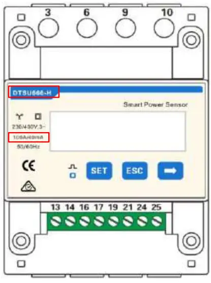
DTSU666-H 250 A/50 mA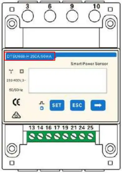
- Nameplate
DTSU666-H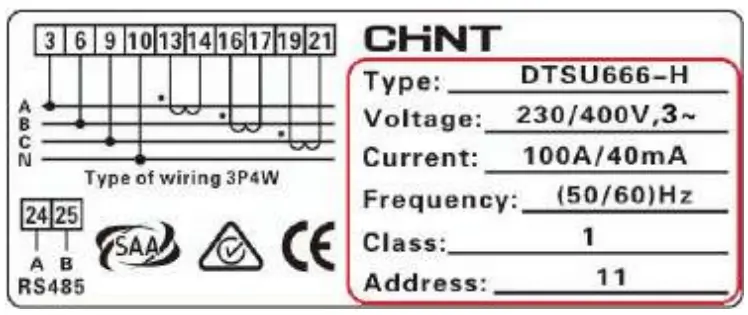
DTSU666-H 250 A/50 mA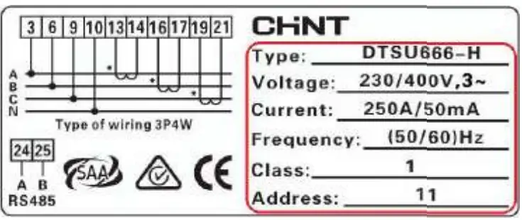
Performance and Specification
| Category | DTSU666-H | DTSU666-H 250 A/50 mA |
| Nominal voltage | 230 V AC / 400 V AC | 230 V AC / 400 V AC |
| Current Measurement range | 0–100 A | 0–250 A |
| Power grid system | 3P4W | 3P4W or 3P3W |
Port Definition
Voltage Input: 3×230/400 V or 3×400 V
Current Transformer(CT): 100 A/40 mA or 250 A/50 mA;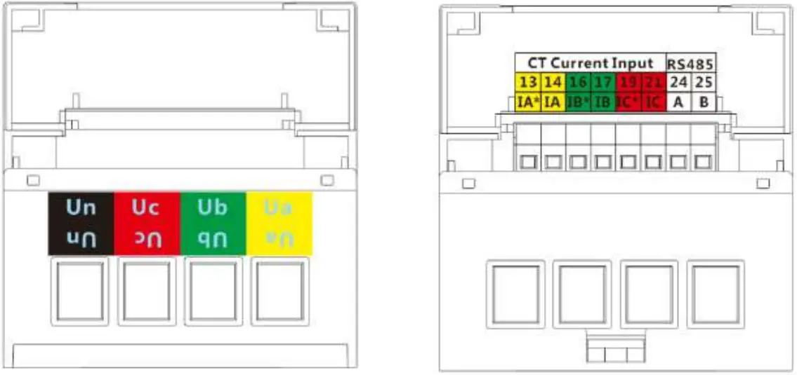
Installing the DTSU666-H and DTSU666-H 250 A/50 mA
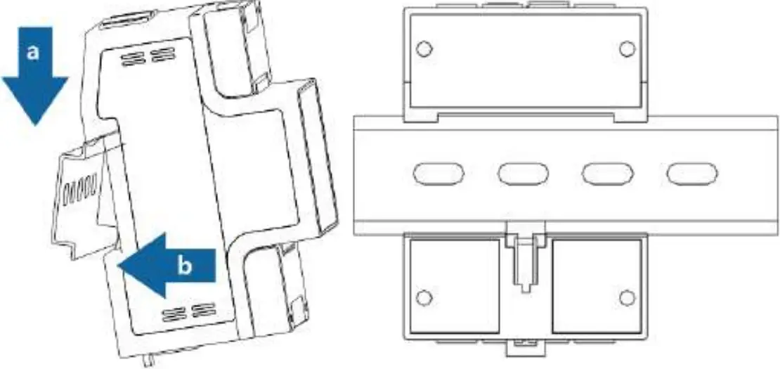
- Install the smart power sensor on the standard din rail of DIN35mm
- Install the Smart Power Sensor to the standard din rail from the top to the bottom, and then push the instrument to the din rail from the bottom to the front part.

Installing the Cable
Prepare cables
| Cable | Port | Type | Conductor Cross-sectional Area Range | Outer Diameter | Source | |
| AC power cable | Ua-3 | Four-core outdoor copper cable | 4-6 mm2 | 10-21 mm | Prepared by the customer | |
| Ub-6 | ||||||
| Uc-9 | ||||||
| Un-10 | ||||||
| CT cable | IA*-13 | / | / | / | Manufacturer | |
| IA-14 | / | / | / | |||
| IB*-16 | / | / | / | |||
| IB-17 | / | / | ||||
| IC*-19 | / | / | / | |||
| IC-21 | / | / | / | |||
| Comm. cable | RS485A-24 | S485B-25 | Two-core outdoor shielded twisted pair | 0.25-1 mm2 | 4-11 mm | Manufacturer |
![]() NOTE
NOTE
A fuse and a thermistor are connected to each phase of Ua, Ub, and Uc inside the power meter to prevent damage caused by external short circuits. Ua, Ub, and Uc do not need to be protected by external fuses.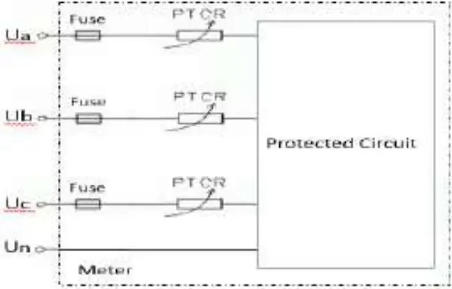
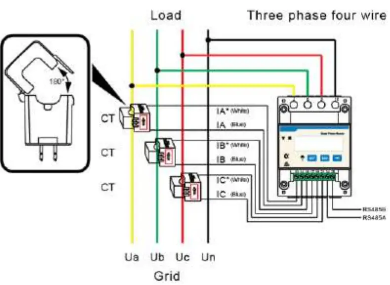
Wiring Diagram–Three Phase Four Wire
Support model:
- DTSU666-H
- DTSU666-H 250 A/50 mA
Operating voltage: 0.7–1.3 Un
- Three phase four wire: Connect the Ua, Ub, Uc, Un voltage lines to the 3, 6, 9 and 10 terminals of the collector. Connect current transformer outlets IA*, IA, IB*, IB, IC*, IC to terminals 13, 14, 16, 17, 19, 21 of the collector.
- Connect RS485A and RS485B to the communication host.

![]() NOTE
NOTE
The CT direction must be consistent with the arrow direction as shown in the preceding figure.
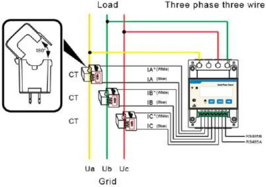
Wiring Diagram–Three Phase Three Wire
Support model:
- DTSU666-H 250 A/50 mA
Operating voltage: 0.7–1.3 Un
- Three phase three wire: Connect the Ua, Uc, Ub voltage lines to the 3, 9 and 10 terminals of the collector. Connect current transformer outlets IA*, IA, IB*, IB, IC*, IC to terminals 13, 14, 16, 17, 19, 21 of the collector.
- Connect RS485A and RS485B to the communication host.

![]() NOTE
NOTE
The CT direction must be consistent with the arrow direction as shown in the preceding figure
User Interface
Display (Auto loop)
If no button is pressed for 60 seconds, the backlight turns off. Auto loop Switch time = 5s.
No. | Display interface | Description | No. | Display interface | Description |
| 1 | 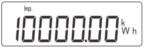 | Imp. activeenergy = 10000.0 kWh | 2 | Exp. active energy= 2345.67 kWh | |
| 3 | Active power= 3.291 kW | 4 | Phase A voltage= 220.0 V | ||
| 5 | 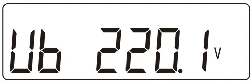 | Phase B voltage= 220.1 V | 6 | 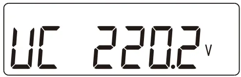 | Phase C voltage= 220.20 V |
| 7 | Phase A current= 5.000 A | 8 | Phase B current= 5.001 A | ||
| 9 | Phase C current= 5.002 A | 10 | 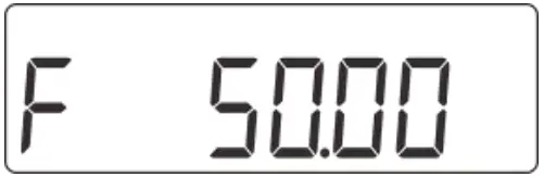 | Frequency freq = 50.00 Hz |
Display (Change by key ” “)
| No. | Display interface | Description | No. | Display interface | Description |
| 1 | 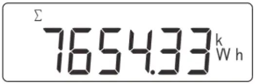 | Comb. active energy= 7654.33 kWh | 2 | Imp. active energy= 10000.0 kWh | |
| 3 | 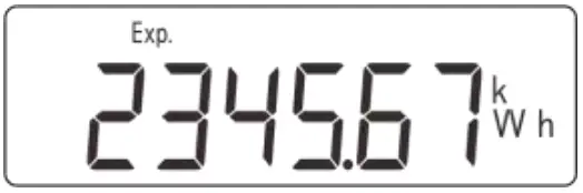 | Exp. active energy= 2345.67 kWh | 4 | 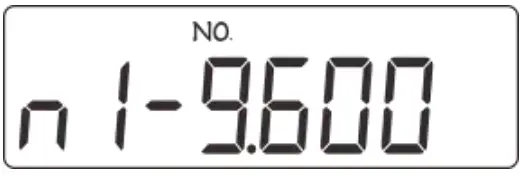 | None parity, 1 stop bit,Baud = 9600bps |
| 5 | 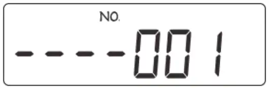 | 001 represents address | 6 | Phase A voltage= 220.0 V | |
| 7 | 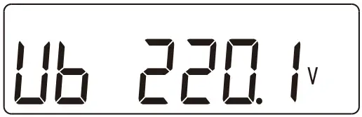 | Phase B voltage= 220.1 V | 8 | 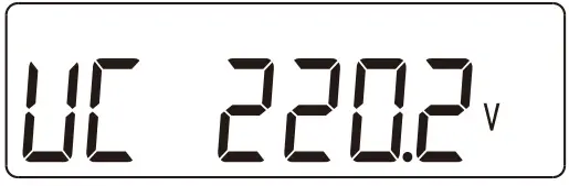 | Phase C voltage= 220.20 V |
| 9 | 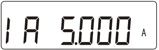 | Phase A current= 5.000 A | 10 | 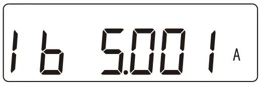 | Phase B current= 5.001 A |
| 11 | 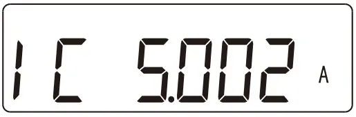 | Phase Ccurrent= 5.002 A | 12 | 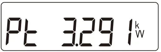 | Phase activepower = 3.291 kW |
| 13 | 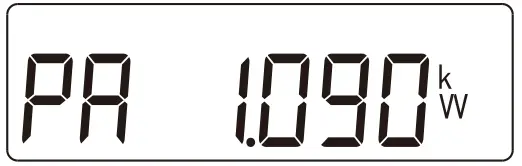 | Phase A active power = 1.090kW | 14 | Phase B active power = 1.101kW | |
| 15 | Phase C active power= 1.100 kW | 16 | Power factor PFt = 0.500 L | ||
| 17 | Phase A power factorPfa = 1.000 L | 18 | 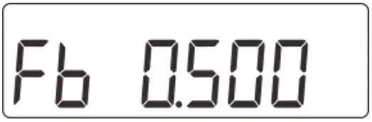 | Phase B power factor PFb =0.500 L | |
| 19 | Phase C power factor PFc =0.500 C | 20 | Frequency freq= 50.00 Hz |
Comb. active energy = Imp. active energy – Exp. active energy
Parameter
| Parameter | Value range | Description |
 | 1: 645; | Settings for communication stop bit and Parity bits: |
| 2: n.2; | 1: Factory mode; | |
| 3: n.1; | 2: None parity, 2 stop bits, n.2; | |
| 4: E.1; | 3: None parity, 1 stop bit, n.1; | |
| 5: O.1; | 4: Even parity, 1 stop bit, E.1; | |
| 5: Odd parity, 1 stop bit, O.1; | ||
| 0: 4.800;1: 9.600; | Communication baud rate:0: 4800 bps;1: 9600 bps; | |
| 11–19 | Communication address |
(Optional) Parameter Setup
![]() NOTE
NOTE
Communications parameters have been configured for the power meter before delivery. If the communication is abnormal, check and set the parameters.
Button description: “SET” represents “confirm” or “cursor shift” (when entering digits), “ESC” represents “exit”, and “→” represents “add”. The password is 701 by default.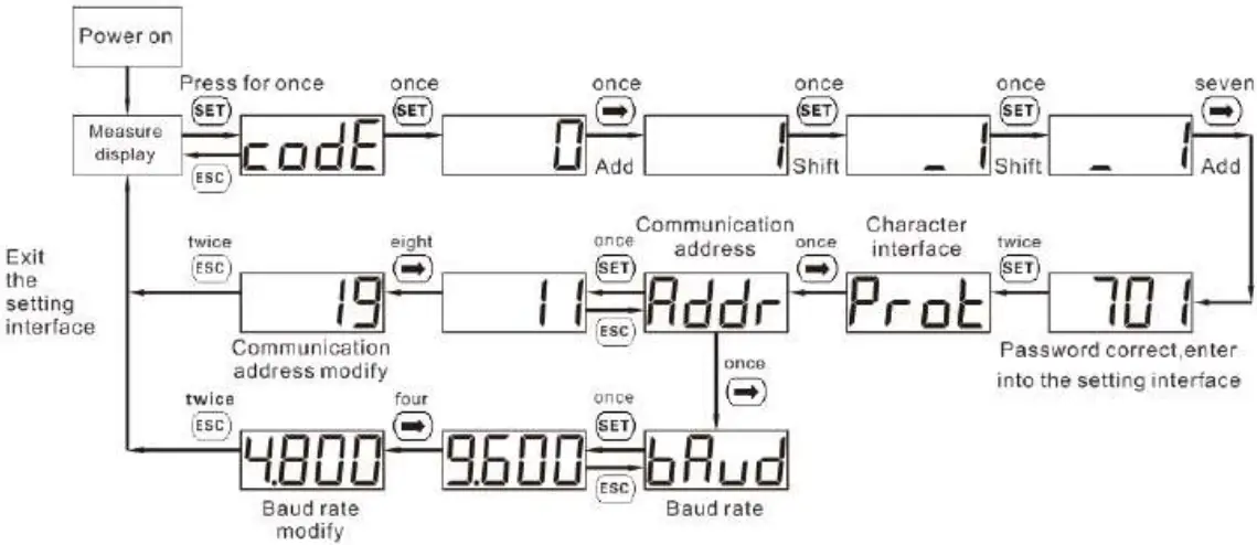
Troubleshooting
| Fault phenomenon | Factor analysis | Elimination method |
| No display after the instrument being powered on |
|
|
| Abnormal RS485 communication |
|
|
| Power metering inaccuracy |
|
|
Verifying the Installation
- Check that all mounting brackets are securely installed and all screws are tightened.
- Check that all cables are reliably connected with correct polarity and no short circuit.
Powering On the System
For details, see DTSU666-H and DTSU666-H 250 A (50 mA) Smart Power Sensor User Manual.
Customer Service Contact
| Customer Service Contact | |||
| Region | Country | Service Support Email | Phone |
| Europe | France | [email protected] | 0080033888888 |
| Germany | |||
| Spain | |||
| Italy | |||
| UK | |||
| Netherlands | |||
| Other countries | For details, see solar.huawei.com. | ||
| Asia Pacific | Australia | [email protected] | 1800046639 |
| Turkey | [email protected] | – | |
| Malaysia | [email protected] | 0080021686868/1800220036 | |
| Thailand | (+66) 26542662 (charged bylocal call) | ||
| 1800290055 (free in Thailand) | |||
| China | [email protected] | 4008229999 | |
| Other countries | [email protected] | 0060-3-21686868 | |
| Japan | Japan | [email protected] | 0120258367 |
| India | India | [email protected] | 1800 103 8009 |
| SouthKorea | South Korea | [email protected] | – |
| North America | USA | [email protected] | 1-877-948-2934 |
| Canada | [email protected] | 1-855-482-9343 | |
| LatinAmerica | Mexico | [email protected] | 018007703456/0052-442-4288288 |
| Argentina | 0-8009993456 | ||
| Brazil | 0-8005953456 | ||
| Chile | 800201866 (only for fixed) | ||
| Other countries | 0052-442-4288288 | ||
| Middle East and Africa | Egypt | [email protected] | 08002229000/0020235353900 |
| UAE | 08002229000 | ||
| South Africa | 0800222900 | ||
| Saudi Arabia | 8001161177 | ||
| Pakistan | 0092512800019 | ||
| Morocco | 0800009900 | ||
| Other countries | 0020235353900 | ||
Huawei Technologies Co., Ltd.
Huawei Industrial Base, Bantian, Longgang, Shenzhen 518129, People’s Republic of China solar.huawei.com
Issue: 03
Date: 2019-09-29