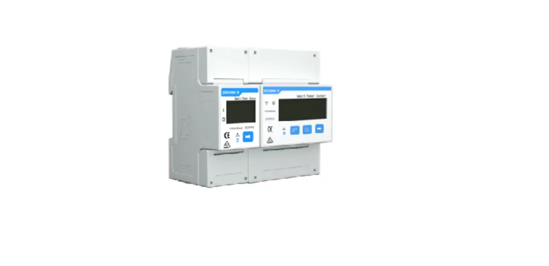
maxsel DTSU666-HW Smart Power Sensor
Overview
Dimensions
DTSU666-HW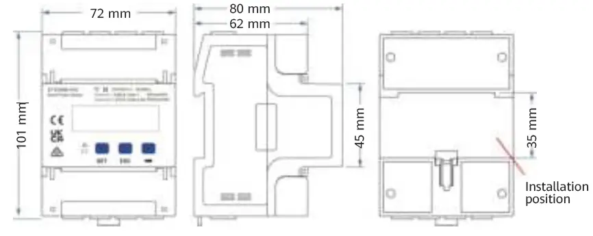
Note: The dimensional tolerance is ± 1 mm.
Appearance
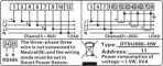
Specifications on the front panel
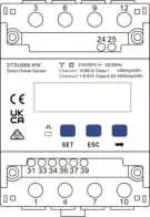
Nameplate
Key Specifications
| Category | DTSU666-HW |
| Nominal voltage | 230 V AC/400 V AC, 50 Hz/60 Hz |
| Current measurement range | Direct connection: 0–80 A Connection through current transformers: > 80 A |
| Voltage measurement range | 90–1000 V (line voltage; potential transformers are required if the voltage is greater than 500 V) |
| Electricity metering accuracy | Class 1 (error within ±1%) |
| Power grid system | Three-phase four-wire or three-phase three-wire |
| Baud rate | 4800/9600/19200/115200 bps (default value: 9600 bps) |
| Operating temperature | –25℃ to +60℃ |
| Installation mode | Guide rail-mounted |
| Certification | CE, RCM, and UKCA |
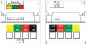
Port Definition
- Input voltage: When the line voltage is less than or equal to 500 V, connect the meter directly. When the line voltage is greater than 500 V, connect the meter through potential transformers.
- Input current: When the input current is 0 A to 80 A, connect the meter directly (channel 1). When the input current is greater than or equal to 80 A, connect the meter through current transformers (channel 2).
Cable Inlet Cable Outlet
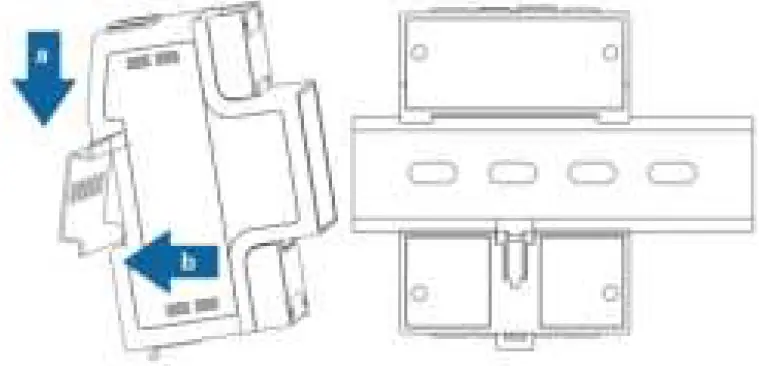
Installing the DTSU666-HW
- Install the Smart Power Sensor on the standard guide rail of DIN35mm.
- Press the Smart Power Sensor downwards onto the guide rail, and then push it in place along the guide rail.
Installing Cables
Preparing Cables
| Cable | Port | Type | Conductor Cross- sectional Area Range | Outer Diameter | Source |
| Channel 1 voltage cable | UA-1 and 3 | Single-core outdoor copper cable | 25 mm2 | 10 mm | Prepared by the customer |
| UB-4 and 6 | |||||
| UC-7 and 9 | |||||
| UN-10 and 12 | |||||
| Channel 2 voltage cable | UA-1 | Single-core outdoor copper cable | 4–25 mm2 | 5–10 mm | Prepared by the customer |
| UB-4 | |||||
| UC-7 | |||||
| UN-10 | |||||
| Channel 2 current transformer cable | IA*-31 |
Single-core outdoor copper cable | 2–4 mm2 | 3–5 mm | Prepared by the customer or supplied with current transformers |
| IA-33 | |||||
| IB*-34 | |||||
| IB-36 | |||||
| IC*-37 | |||||
| IC-39 | |||||
| Communications cable | RS485A-24 | Two-core outdoor shielded twisted pair copper cable | 0.25–1.5 mm2 | 4–11 mm | Supplied by the manufacturer |
| RS485B-25 |
Note: The maximum torque of 1, 3, 4, 6, 7, 9, 10, and 12 terminal screws is 1.7 N·m, and the recommended torque is 0.9–1.1 N·m. The maximum torque of 31, 33, 34, 36, 37, 39, 24, and 25 terminal screws is 0.4 N·m, and the recommended torque is 0.15–0.25 N·m.
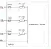
Note: Each phase of UA, UB, and UC in the Smart Power Sensor is connected with a fuse and a thermistor to prevent damage caused by external short circuits. UA, UB, and UC do not need external fuse protection.
Wiring Scenarios
| Current | ≤ 80 A | > 80 A | ≥ 0 A | |||
| Line voltage | ≤ 500 V | > 500 V | ||||
| Connection mode | Current and voltage direct connection | Connection through current transformers and voltage direct connection | Connection through current transformers and potential transformers | |||
| Connection setting | Direct connection: SPEC = 1 (default) | Connection through transformers: SPEC = 0 | ||||
| Current transformation ratio | CT = 1 (default) | CT = Ratio of the installed current transformer | ||||
| Potential transformation ratio | PT = 1.0 (default) | PT = Ratio of the installed potential transformer | ||||
| Wiring mode | 3P4W: net = n.34 (default) | 3P3W: net = n.33 | 3P4W: net = n.34 (default) | 3P3W: net = n.33 | 3P4W: net = n.34 (default) | 3P3W: net = n.33 |
Note: You need to set parameters after cable connections are complete. For details, see section 4 “Display and Parameter Settings”.
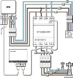
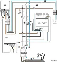
Current and Voltage Direct Connection (Current ≤ 80 A and Line 3.3 Voltage ≤ 500 V)
Smart Logger networking
- Three-phase four-wire connection
Note: In the SmartLogger networking scenario, the power meter is connected to the SmartLogger. In the non-SmartLogger networking scenario, the power meter is connected to the inverter.
- Shield layer of the signal cable
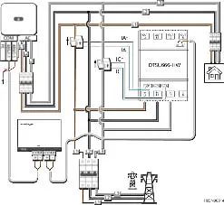
- Three-phase three-wire connection

- Shield layer of the signal cable
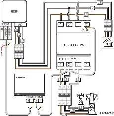
Smart Dongle networking
- Three-phase four-wire connection
- Shield layer of the signal cable

- Shield layer of the signal cable
- Three-phase three-wire connection
- Shield layer of the signal cable

- Shield layer of the signal cable
Note: You need to set parameters after cable connections are complete. For details, see section 4 “Display and Parameter Settings”.
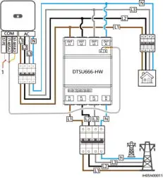
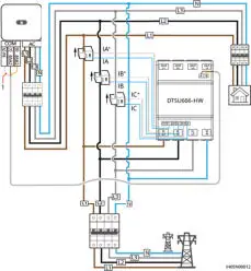
Connection Through Current Transformer and Voltage Direct Connection (Current > 80 A, Line Voltage ≤ 500 V)
Current transformers specifications: The accuracy class is 0.5, and the current on the secondary side is 1 A or 5 A.
SmartLogger networking
- Three-phase four-wire connection
Note: In the SmartLogger networking scenario, the power meter is connected to the SmartLogger. In the non-SmartLogger networking scenario, the power meter is connected to the inverter.- Shield layer of the signal cable

- Shield layer of the signal cable
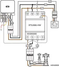
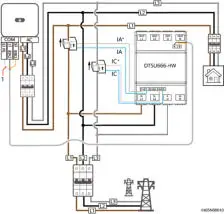
- Three-phase three-wire connection

Caution: Please ensure that the ground cable is installed securely. Poor grounding may cause electric shocks.
Note:
- You need to set parameters after cable connections are complete. For details, see section 4 “Display and Parameter Settings”.
- For the three-phase three-wire connection, phase B does not need to connect to a current transformer.
Smart Dongle networking
- Three-phase four-wire connection
- Shield layer of the signal cable

- Shield layer of the signal cable
- Three-phase three-wire connection
Caution: Please ensure that the ground cable is installed securely. Poor grounding may cause electric shocks.
Note: - You need to set parameters after cable connections are complete. For details, see section 4 “Display and Parameter Settings”.
- For the three-phase three-wire connection, phase B does not need to connect to a current transformer.

- Shield layer of the signal cable
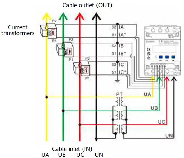
Connection Through Current Transformer and Potential
Transformer (Current ≥ 0 A, Line Voltage > 500 V)
- Three-phase four-wire connection
 Three-phase three-wire connection
 Three-phase three-wire connection
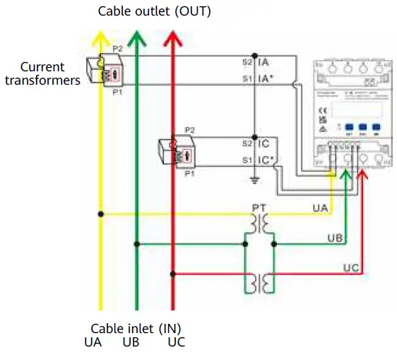
Caution: Please ensure that the ground cable is installed securely. Poor grounding may cause electric shocks.
Note: You need to set parameters after cable connections are complete. For details, see section 4 “Display and Parameter Settings”.
Display and Parameter Settings
Display
The button → is used to switch the displays. Set parameter disp to enable the rotation display function.
| No. | Display | Description | No. | Display | Description |
| 1 | Positive active energy = 10000.00 kWh | 2 | Negative active energy = 2345.67 kWh | ||
|
3 | None parity, 8 data bits, and 1 stop bit; baud rate = 9600 bps (default) |
4 | 011 represents address (default) | ||
| 5 | 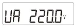 | Phase A voltage = 220.0 V | 6 | 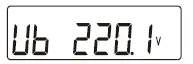 | Phase B voltage = 220.1 V |
| 7 | 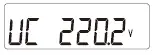 | Phase C voltage = 220.2 V | 8 | 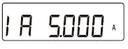 | Phase A current = 5.000 A |
| 9 | 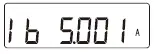 | Phase B current = 5.001 A | 10 | 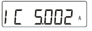 | Phase C current = 5.002 A |
| 11 | 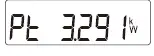 | Total phase active power = 3.291 kW | 12 | 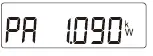 | Phase A active power = 1.090 kW |
| 13 | 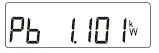 | Phase B active power = 1.101 kW | 14 | 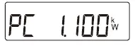 | Phase C active power = 1.100 kW |
| 15 | 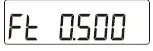 | Total phase power factor PFt = 0.500 | 16 | Phase A power factor PFa = 1.000 | |
| 17 | Phase B power factor PFb = 0.500 | 18 | Phase C power factor PFc = –0.500 |
Parameter Settings
| No. | Parameter | Value Range | Description |
| 1 | 1–6553 | Current transformer ratio | |
| 2 | 0.1–999.9 | Potential transformer ratio | |
|
3 |
| 1: 645 2: n.2 3: n.1 4: E.1 5: 0.1 | Communication protocol switchover: 1: Factory mode 2: None parity, 2 stop bits, n.2 3: None parity, 1 stop bit, n.1 4: Even parity, 1 stop bit, E.1 5: Odd parity, 1 stop bit, 0.1 |
| 4 | 1–247 | Modbus communication address | |
|
5 |
| 0: 1.200 1: 2.400 2: 4.800 3: 9.600 4: 19.20 5: 115.2 | Communication baud rate: 0: 1200 bps
|
| 6 | 0: n.34 1: n.33 | Wiring mode: 0: n.34, three-phase four-wire 1: n.33, three-phase three-wire | |
| 7 | 0–30 | Rotation display time (s): 0: Fixed display 1–30: Time interval of rotation display | |
|
8 |
0–30 | Backlight illumination time control (minutes): 0: Steady on 1–30: Time of backlight illumination without key operation | |
| 9 | 0: ct 1: dc | Channel switchover: 0: Transformer connection 1: Direct connection |
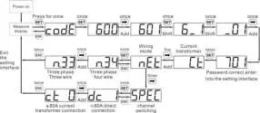
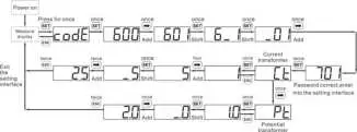
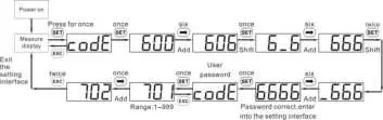
Parameter Setting Operations
Button description: SET means “confirm” or “cursor move” (when inputting numbers or parameters), ESC means “exit”, and → means “add”. The default user password is 701.
- Set wiring mode (three-phase four-wire or three-phase three-wire) and channel switchover (direct connection or current transformer connection):

- Set the current transformation ratio or potential transformation ratio:

- Set communication address or baud rate:

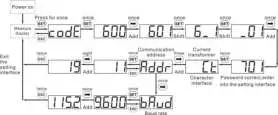
Note:The communication parameters are set for the Smart Power Sensor before delivery. If the communication is abnormal, check and set the parameters.
- Modify user password:

Troubleshooting
| Symptom | Cause Analysis | Troubleshooting Method |
| No display after power-on |
|
|
| Abnormal RS485 communication |
|
|
| Inaccurate metering |
|
|
Installation Verification
- Check that all mounting brackets are securely installed and all screws are tightened.
- Check that all cables are reliably connected in correct polarity without short circuit.
Customer Service Contact
| Customer Service Contact | |||
| Region | Country | Tel | |
| Europe | France | [email protected] | 0080033888888 |
| Germany | |||
| Spain | |||
| Italy | |||
| UK | |||
| Netherlands | |||
| Other countries | For details, see solar.huawei.com. | ||
| Asia Pacific | Australia | [email protected] | 1800046639 |
| Turkey | [email protected] | – | |
| Malaysia | [email protected] | 0080021686868 /1800220036 | |
| Thailand | (+66) 26542662 (local call rates) | ||
| 1800290055 (free in Thailand) | |||
| China | [email protected] | 400-822-9999 | |
| Other countries | [email protected] | 0060-3-21686868 | |
| Japan | Japan | [email protected] | 0120258367 |
| India | India | [email protected] | 1800 103 8009 |
| South Korea | South Korea | [email protected] | – |
| North America | USA | [email protected] | 1-877-948-2934 |
| Canada | [email protected] | 1-855-482-9343 | |
| Latin America | Mexico | [email protected] | 018007703456 /0052-442-4288288 |
| Argentina | 0-8009993456 | ||
| Brazil | 0-8005953456 | ||
| Chile | 800201866 (fixed-line only) | ||
| Other countries | 0052-442-4288288 | ||
| Middle East and Africa | Egypt | [email protected] | 08002229000/0020235353900 |
| UAE | 08002229000 | ||
| South Africa | 0800222900 | ||
| Saudi Arabia | 8001161177 | ||
| Pakistan | 0092512800019 | ||
| Morocco | 0800009900 | ||
| Other countries | 0020235353900 | ||


