![]()
DDSU666-H Smart Power Sensor
User Manual

HUAWEI TECHNOLOGIES CO., LTD.
Copyright © Huawei Technologies Co., Ltd. 2021. All rights reserved.
No part of this document may be reproduced or transmitted in any form or by any means without the prior written consent of Huawei Technologies Co., Ltd.
Trademarks and Permissions
and other Huawei trademarks are trademarks of Huawei Technologies Co., Ltd.
All other trademarks and trade names mentioned in this document are the property of their respective holders.
Notice
The purchased products, services, and features are stipulated by the contract made between Huawei and the customer. All or part of the products, services, and features described in this document may not be within the purchase scope or the usage scope. Unless otherwise specified in the contract, all statements, information, and recommendations in this document are provided “AS IS” without warranties, guarantees, or representations of any kind, either express or implied.
The information in this document is subject to change without notice. Every effort has been made in the preparation of this document to ensure accuracy of the contents, but all statements, information, and recommendations in this document do not constitute a warranty of any kind, express or implied.
Huawei Technologies Co., Ltd.
Address: Huawei Industrial Base
Bantian, Longgang
Shenzhen 518129
People’s Republic of China
Website: https://e.huawei.com
About This Document
Purpose
This document describes the DDSU666-H Smart Power Sensor in terms of its functions, electrical properties, and structure.
Figures provided in this document are for reference only.
Intended Audience
This document is intended for:
- Sales engineers
- Technical support engineers
- Maintenance engineers
Intended Audience
This document is intended for:
- Sales engineers
- Technical support engineers
- Maintenance engineers
Symbol Conventions
The symbols that may be found in this document are defined as follows.
| Symbol | Description |
| Indicates a hazard with a high level of risk which, if not avoided, will result in death or serious injury. | |
| Indicates a hazard with a medium level of risk which, if not avoided, could result in death or serious injury. | |
| Indicates a hazard with a low level of risk which, if not avoided, could result in minor or moderate injury. | |
| NOTICE | Indicates a potentially hazardous situation that, if not avoided, could result in equipment damage, data loss, performance deterioration, or unanticipated results. NOTICE is used to address practices not related to personal injury. |
| NOTE | Supplements the important information in the main text. NOTE is used to address information not related to personal injury, equipment damage, and environmental deterioration. |
Change History
Changes between document issues are cumulative. The latest document issue contains all updates made in previous issues.
Issue 03 (2021-10-10)
- Updated 2.3 Application Scenarios.
- Updated 2.7 Installing the DDSU666-H Cable.
Issue 02 (2021-03-01)
- Updated 2.6 Installing the DDSU666-H.
- Updated 2.7 Installing the DDSU666-H Cable.
Issue 01 (2018-03-01)
This issue is the first official release.
Safety Precautions
General Safety
- Follow the precautions and special safety instructions provided by Huawei when operating this product. Personnel who plan to install or maintain Huawei devices must receive thorough training, understand all necessary safety precautions, and be able to correctly perform all operations. Huawei will not be liable for any consequences that are caused by the violation of general safety regulations and device usage safety standards.
- Before performing operations, read through this manual and follow all the precautions to prevent accidents. The “DANGER”, “WARNING”, “CAUTION”, and “NOTICE” statements in this document do not represent all the safety instructions. They are only supplements to the safety instructions.
- Operation personnel should comply with local laws and regulations. The safety instructions in this document are only supplements to local laws and regulations.
- Do not operate the product or handle cables during thunderstorms.
- Before operating the product, remove any conductors such as jewelry or watches.
- Use insulated tools during operations.
- Bolts should be tightened with a torque wrench and marked using red or blue color. Installation personnel should mark tightened bolts in blue. Quality inspection personnel should confirm if the bolts are tightened and then mark them in red. If screws or bolts used to secure the device are not tightened to the required torque, the device may fall from the mounting bracket.
- Follow specified procedures during installation and maintenance. Do not attempt to alter the device or deviate from the recommended installation procedures without prior consent from the manufacturer.
- Install the product in strict accordance with the quick guide.
Disclaimer
Huawei shall not be liable for any consequence caused by any of the following events:
- Transportation damage
- The storage conditions do not meet the requirements specified in this document.
- Incorrect installation or use
- Installation or use by unqualified personnel
- Failure to obey the operation instructions and safety precautions in this document
- Operation in extreme environments which are not covered in this document The DDSU666-H operates beyond specified ranges.
- Unauthorized modifications to the product or software code or removal of the product
- Device damage due to force majeure (such as lightning, fire, and storm)
- The warranty expires and the warranty service is not extended
- Installation or use in environments that are not specified in related international standards
Personnel Requirements
Only certified electricians are allowed to install, connect cables for, maintain, troubleshoot, and replace the DDSU666-H.
- Operation personnel should receive professional training.
- Operation personnel should read through this document and follow all the precautions.
- Operation personnel should be familiar with the safety specifications of the electrical system.
- Operation personnel should understand the composition and working principles of the grid-tied PV power system and local regulations.
- Operation personnel must wear proper personal protective equipment (PPE).
Protect Labels
- Do not scrawl or damage any warning labels on the DDSU666-H because these labels contain important information about the safe operation.
- Do not scrawl or damage the nameplate on the back of the DDSU666-H because it contains important product information.
Installation
- Ensure that the DDSU666-H is not connected to a power supply or powered on before finishing the installation.
- To allow proper heat dissipation and installation, maintain appropriate clearances between the DDSU666-H and other objects.
Electrical Connections![]() DANGER
DANGER
Before connecting cables, ensure that the DDSU666-H is not damaged in any way.
Otherwise, electric shocks or fire may occur.
- Ensure that all electrical connections comply with local electrical standards.
- Ensure that the cables used in a grid-tied PV system are properly connected and insulated and meet all specification requirements.
Operation![]() DANGER
DANGER
High voltage may cause an electric shock, which results in serious injury, death, or serious property damage from the DDSU666-H in operation. Strictly comply with the safety precautions in this document and associated documents when operating the DDSU666-H.
- Do not touch an energized DDSU666-H because it has a high temperature.
- Follow local laws and regulations when operating the device.
Maintenance and Replacement
DANGER
High voltage may cause an electric shock, which results in serious injury, death, or serious property damage from the DDSU666-H in operation. Therefore, before maintenance, power off the DDSU666-H and strictly comply with the safety precautions in this document and associated documents to operate the DDSU666H.
- Maintain the DDSU666-H with sufficient knowledge of this document and proper tools and testing devices.
- Temporary warning signs or fences must be placed to prevent unauthorized people from entering the site.
- The DDSU666-H can be powered on only after all faults are rectified. Failing to do so may escalate faults or damage the device.
- During the maintenance, observe ESD precautions and wear ESD gloves.
Overview
Product Overview
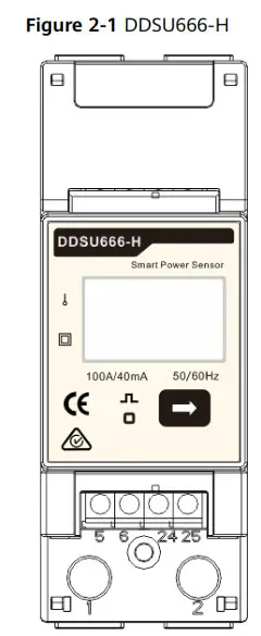
Type DDSU666-H Smart Power Sensor (hereinafter referred to as the ” Sensor “) is specially designed for the distributed photovoltaic system, to be a new Smart power sensor, combined with measurement and communication, mainly applied into the measurement for electrical quantity including voltage, current, power, frequency, power factor, active energy, etc. in the electrical circuit. It can realize networking with the external device through the RS485 communication interface. Adopting the standard DIN35mm din rail mounting, structural module design, it is characterized with small volume, easy installation and networking, etc. This performance index of the meter conforms to the following relevant technical standard:
- EN 61326-1:2013
- IEC 61326-1:2012
- EN 61326-2-1:2013
- IEC 61326-2-1:2012
- EN 61010-1:2010
- IEC 61010-1:2010
- EN 61010-2-1:2010
- IEC 61010-2-1:2010
Working Principles
Conceptual Diagram
The Sensor can convert the voltage and current signal to be the signal that can be identified by MCU through the sampling circuit, MCU will calculate and convert it into energy, power, power factor, and other electrical quantity by calculating the signals in the sampling circuit, transferring to users through communication and meanwhile save the data in the storage circuit. Please see the conceptual diagram of the Sensor as figure 2-2: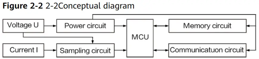
Functions
- Metering function:
Accurately metering the positive/ reverse active energy and combined active energy, no storage data loss for the sensor after power interruption. - Measurement function of electrical parameters
The sensor can accurately measure electrical parameters including power, voltage, current, frequency, power factor, etc. - Display function
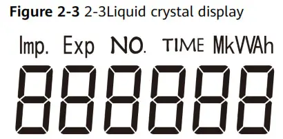
The instrument adopts a field LCD design, characterized with display function for electrical parameters and energy data. Please see the LCD display in Figures 2-3.
The display bit of energy measurement value can be six bits, with a display range from 0 to 999999 kWh.
- Cyclic display
Characterized with a cyclic display function, the shift time of cyclic display is 5 s.
Please see the cyclic displayed item in table 2-1.
a. Cyclic displayed items
| No | Content | Description |
| 1 | 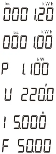 | Current positive active energy Imp = 1.20 kWh |
| 2 | Current reverse active energy Exp = 1.00 kWh | |
| 3 | Active power P=1.100 kW | |
| 4 | Voltage U U=220.0 V | |
| 5 | Current I=5.000 A | |
| 6 | Frequency F=50.00 Hz |
- Button display
The instrument has a button display and backlight function, please see the button displayed items in table2-2.
a. 2-2Button displayed items
| No. | Content | Description |
| 1 | 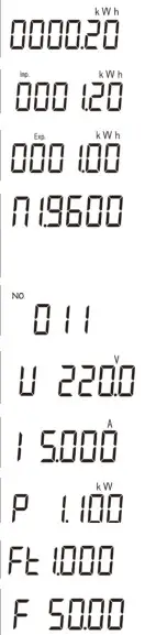 | Current combined active energy =0.20 kWh |
| 2 | Current positive active energy Imp = 1.20 kWh | |
| 3 | Current reverse active energy Exp = 1.00 kWh | |
| 4 | n.1. data format to be eight bits, none parity bit and one stop bit. 9600: baud rate to be 9600 bps 4800: baud rate to be 4800 bps | |
| 5 | Comm.Add=11 | |
| 6 | Voltage U=220.0 V | |
| 7 | Current I=5.000 A | |
| 8 | Active power P=1.100 kW | |
| 9 | Power factor Ft=1.000 | |
| 10 | Frequency F=50.00 Hz |
Note: Backlight closed without button operation for sixty seconds.
Note: The combined active energy default by the factory is equal to positive active energy.
- Parameter setting function
The sensor can set the communication address and baud rate through buttons.
Setting method please see figure 2-4: Long press the button 3s, the sensor will automatically enter into the communication address setting interface, with cyclic display for setting display interface of baud rate and communication address. Please press the button when required for baud rate or communication address settings, it will exit to communication address and baud rate settings without button operation for twenty seconds.
The details are as follows: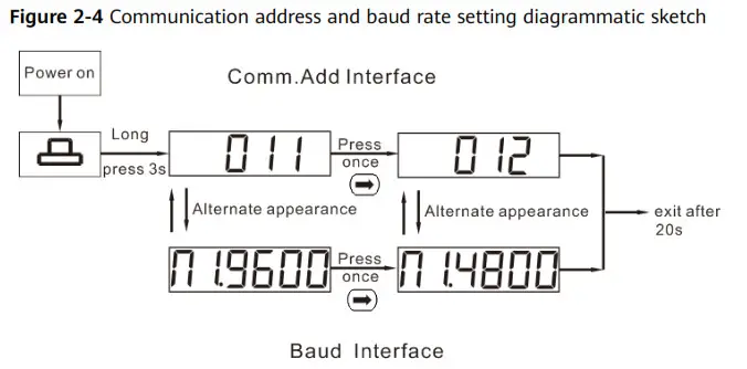
- Communication function
The sensor is equipped with one RS485 communication interface, with baud rate changed among 4800bps and 9600bps. The default baud rate is 9600bps with check bit and stop bit to be n.1, communication address (see factory number or LCD display), support ModBus—RTU protocol.
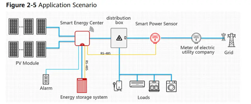
Application Scenarios
Scenario 1: The sensor is used to realize power restriction of the power grid with charge and discharge control towards energy storage in the household inverter scheme, which is the core component for household energy management. It adopts RS485 communication, which can realize the electrical quantity measurement, energy metering function and in respond to the upper host for the real-time data query.![]() NOTE
NOTE
The smart power sensor is mainly used for power control at the grid-connection point. The measured energy yield and electricity consumption are for reference only and cannot be used as a basis for calculating electricity fees. Electricity fee measurement is subject to the meter provided by the grid company.
Model Naming Conventions
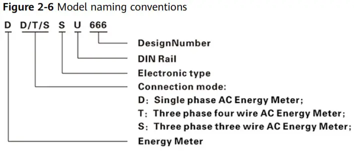
1. Model Specification
| Model No. | Accuracy grade | Referenced voltage | Current specification | Collector constant | Type |
| DDSU666-H | Active Class 1 | 230 V | 100 A/40 mA | 800 imp/kWh | Via transformer |
Product Structure
Outline dimension: 36mmx98mmx66mm; Din-rail mounting dimension: 35 mm, for the outline and installation dimension, please see Figure 2-7 as below: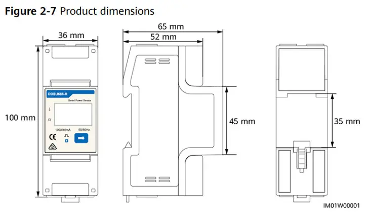
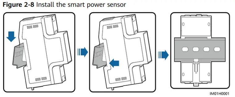
Installing the DDSU666-H
- Install the smart power sensor on the standard din rail of DIN35 mm.
- Install the Smart Power Sensor to the standard din rail from the top to the bottom, and then push the instrument to the din rail from the bottom to the front part.
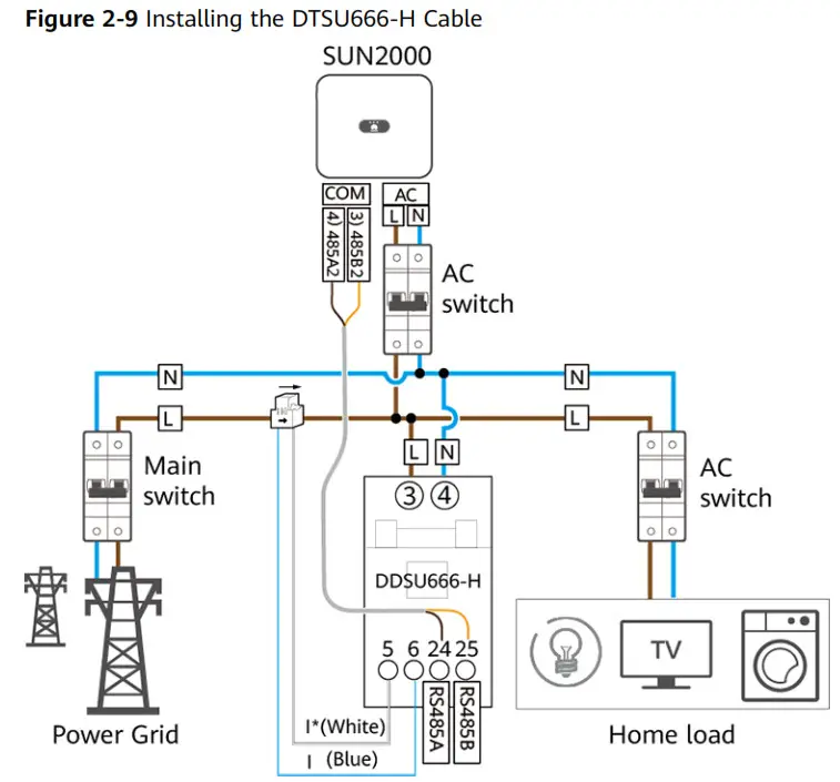
Installing the DDSU666-H Cable
| Cable | DDSU666-H | Type | Conductor Cross-sectional Area Range | Outer Diameter | Source |
| AC power cable | L – 3 N -4 | Two-core (L and N) outdoor copper cable | 4-6 mm2 | 10-21 mm | Prepared by the customer |
| Cable | DDSU666-H | Type | Conductor Cross-sectional Area Range | Outer Diameter | Source |
| CT cable | I’ – 5 | – | – | – | Manufacturer |
| I – 6 | – | – | |||
| Comm. cable | RS485A – 24 | Two-core outdoor shielded twisted pair | 0.20-1 mm2 | 4-11 mm | Manufacturer |
NOTE
- The minimum cable diameter must comply with local cable standards.
- The factors that affect cable selection include the rated current, cable type, routing mode, ambient temperature, and maximum expected line loss.
- Connect the L, N voltage lines to the 3, 4 terminals of the collector.
- Connect current transformer outlets I*, I to terminals 5, 6 of the collector.
- Connect RS485A and RS485B to the communication host.
System Maintenance
Troubleshooting
Table 3-1 Common alarm and troubleshooting measures
| Fault phenomenon | Factor analysis | Elimination method |
| No display after the instrument is powered on | 1. Incorrect wiring mode; 2. Abnormal voltage supplied for the instrument; | 1. If the wiring mode is incorrect, please connect based on the correct wiring mode (see the wiring diagram). 2. If the supplied voltage is abnormal, please supply the voltage on the instrument specification. |
| Abnormal RS485 communication | 1. The RS485 communication cable is disconnected, short circuit or reversely connected. 2. The address, baud rate, data bit, and parity bit of the instrument is not in accordance with the host computer; | 1. If any problems with the communication cable, please reconnect or change the cable. 2. Set the address, baud rate, data bit, parity bit to be the same as the host computer through buttons, for button settings, please see parameter setting. |
| Inaccurate for energy metering | 1. Incorrect wiring, please check whether the corresponding phase sequence of voltage and current is correct. 2. Check whether the high & low end of the current transformer inlet is reversely connected. Please observe the power of Pa, Pb, Pc, to be abnormal if any negative values. | If the wiring mode is incorrect, please connect based on the correct wiring mode (see the wiring diagram). |
NOTE
Contact the installation vendor if all failure analysis procedures listed above are completed and the fault still exists.
Technical Specifications
Environmental Specifications
Table 4-1 Environmental specification
| Item | Specifications |
| Regulated working temperature range | -25°C to +60°C |
| Limited working temperature range | -35°C to +70°C |
| Relative humidity (Annual average) | ≤ 75% RH |
| Atmospheric pressure | 86–106 kPa |
Main technical performance and parameter
4.2.1 Electrical parameter
Table 4-2 Electrical parameter
| Regulated working voltage range | 176–288 VAC |
| Extended working voltage range | 0.7–1.3 Un |
| Working frequency range | 45–65 Hz |
4.2.2 Percentage error
Table 4-3 The percentage error of the sensor cannot exceed the following corresponding limited value
| Current value | Power factor | The percentage error limitation of various grade instruments | ||||||
| Via transformer | Class 1 | |||||||
| 0.02 In 5 I <0.05 In | 1 | ±1.5 | ||||||
| 0.05 In 515 Imax | 1 | ±1.0 | ||||||
| 0.05 In 51 <0.1 In | 0.5 L | ±1.5 | ||||||
| 0.8 C | ±1.5 | |||||||
| 0.1 In 5 15 !max | 0.5 L | ±1.0 | ||||||
| 0.8 C | ±1.0 | |||||||
| When users have a special requirement | 0.25 L | ±3.5 | ||||||
| 0.1 In 515 !max | 0.5 C | ±2.5 | ||||||
4.2.3 Start
Table 4-4 Under the referenced voltage and Table A-1, the sensor starts and continuously meters the electrical energy
| Sensor | Energy meter grade | Power factor |
| Class 1 | 1 | |
| Direct connect | 0.004 Ib | |
| Via transformer | 0.002 Ib |
4.2.4 Deflection
When applying voltage while the current circuit has no current, the test output of the instrument shall not produce a superfluous pulse. When testing, the current circuit shall be disconnected and the applied voltage of the voltage circuit shall be 115% of the referenced voltage.
The shortest testing time dt: 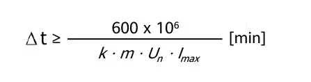
For the instrument of class 1:
From the formula: k represents energy meter constant (imp/kWh), m represents the testing component quantity, Un represents the referenced voltage (V), Imax represents the large current (A).
4.2.5 Other technical parameters
Table 4-5 Other technical parameters
| Scale range | 0–999999.99 kWh |
| Communication protocol | Modbus-RTU protocol |
EMC Specifications
EMC performance of the meter conforms to the following relevant technical standard:
- IEC 61326-1:2012
- IEC 61326-2-1:2012
- EN 61326-1:2013
- EN 61326-2-1:2013
- EN61000-3-2:2005/A2:2009
- EN61000-3-3:2008
Structure Specifications
4.4.1 Structure specifications
Table 4-6 Structure specifications
| Item | Specifications |
| Installation mode | Directly stuck the sensor on the din rail and finally install it on the power distribution box. 1. When installing, please firstly stuck one side of the card slot and then forcibly stuck it on the din rail. 2. When disassembling, please use a screwdriver to forcibly hold the flexible card and then take out the sensor. |
| Dimensions (H x W x D) | 36 mm x 100 mm x 65.5 mm (±0.5 mm) |
| Weight | 5 0.3 kg |
Acronyms and Abbreviations B
| D | |
| DC | direct current |
| E | |
| EFT | electrical fast transient |
| EMI | electromagnetic interference |
| EMS | electromagnetic susceptibility |
| ESD | electrostatic discharge |
| M | maximum power point tracking |
| MPPT | |
| P | power line communication |
| PLC | radiated emission |
| R | radiated susceptibility |
| RE | |
| RS |


