
HUAWEI SmartLi 3.0 Short Term Backup Power
Installation Preparations
NOTE
- Before installation, read the user manual carefully to get familiar with product information and safety precautions.
- Use insulated tools during installation and operations.
- Only qualified professionals or trained personnel are allowed to install, commission, and maintain the battery cabinet. Otherwise, personal injury or equipment damage may occur, and the caused battery cabinet damage is not covered under any warranty or service agreement.
WARNING
- If the battery cabinet is installed but not powered on, manually powered off, or discharged, avoid keeping it at low SOC for an extended period. Recharge the battery cabinet in a timely manner according to the instructions in “Operations > Recharge Requirements for Batteries with Low SOC” in the user manual. Otherwise, batteries may be damaged due to overdischarge.
- It is recommended that an independent battery room be used. Before installing battery modules, prepare fire extinguishing facilities, such as firefighting sands and liquid carbon dioxide fire extinguishers, according to the construction regulations. Before operation, ensure that the battery room is equipped with a fire extinguishing system that complies with local regulations.


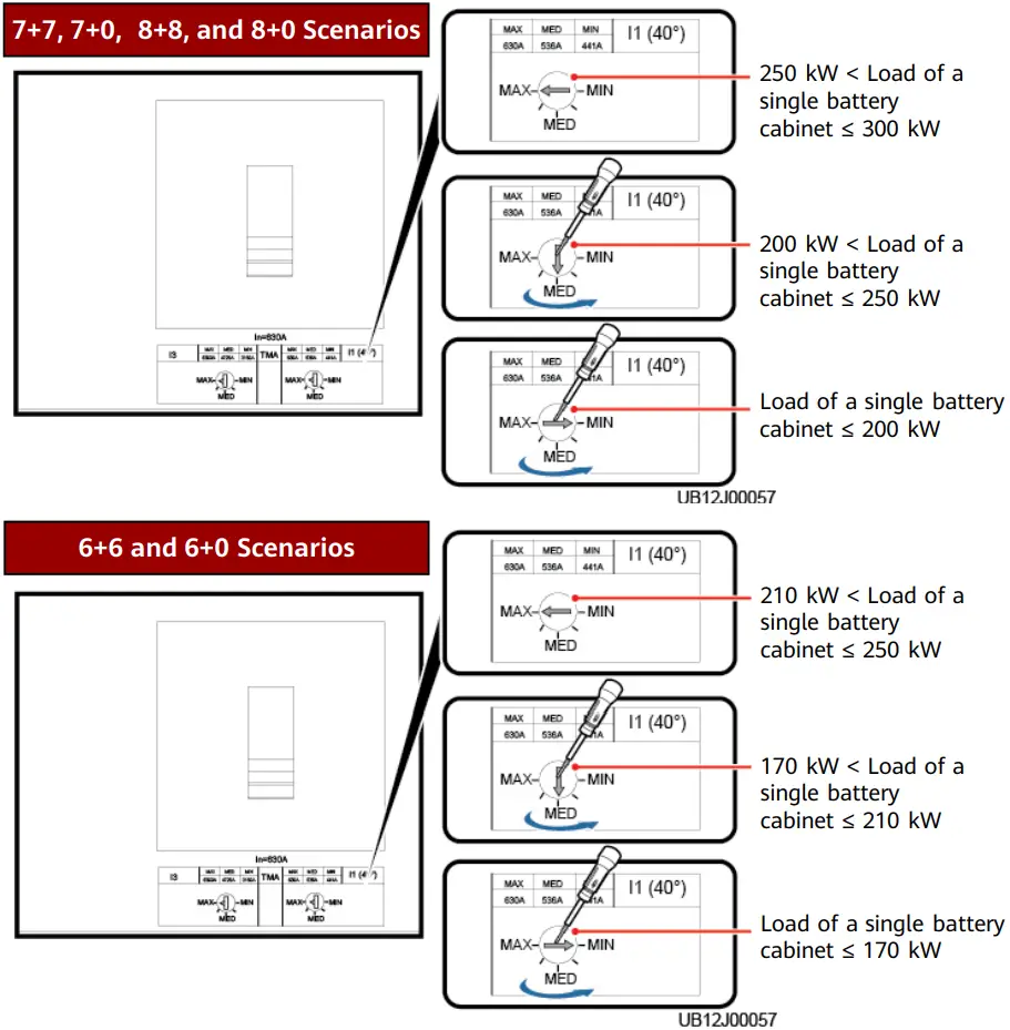
7+7, 7+0, 8+8, and 8+0 Scenarios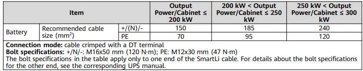
6+6 and 6+0 Scenarios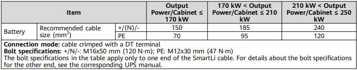
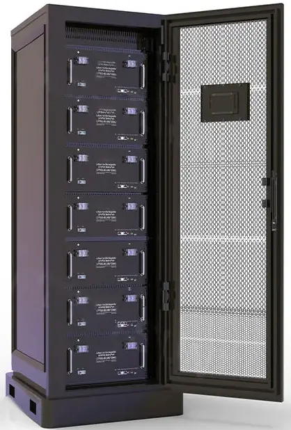
Appearance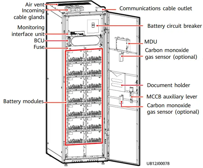
Space Planning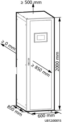
Installing Cabinets
Unpacking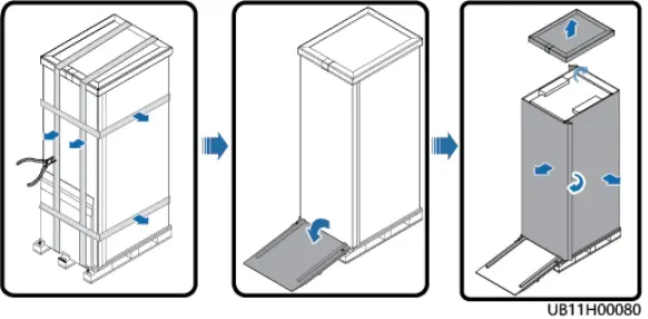
Removing the Pallet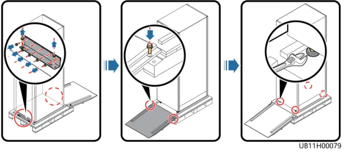
WARNING
Do not transport a cabinet with battery modules installed. If the cabinet needs to be transported or moved, remove the battery modules first.
Secured Installation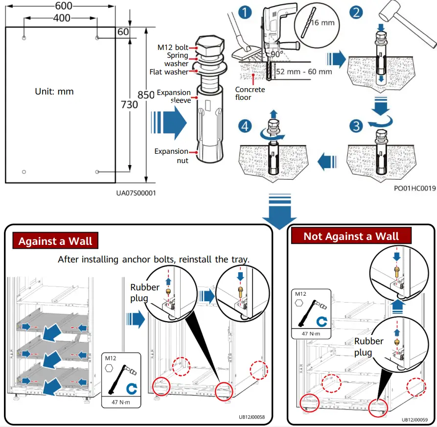
Against a Wall
After installing anchor bolts, reinstall the tray.
Not Against a Wall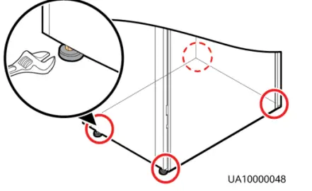
Non-Secured Installation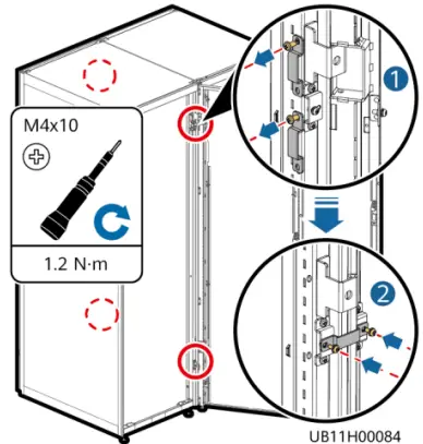
Adjust the anchor bolts until the castors hang in the air, ensure that the anchor bolts fully support the cabinet, and use a level instrument to check that the cabinet is level.
Combining Cabinets
NOTE
If the cabinet is installed against a wall, install only the front connecting plates.
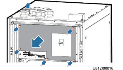
Installing a Ground Cable
- Remove the PDU cover and the ground cable gland nut and sealing plugs.

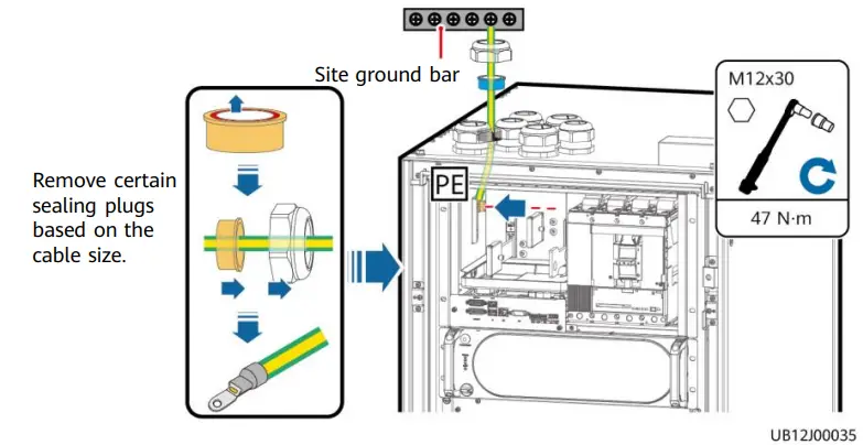
- Install a ground cable.


- Reinstall the sealing plugs. (The sealing plugs must be completely inserted into the gland to facilitate the reinstallation of the gland nut.)
- Reinstall the gland nut with a torque of 8 N·m.
Installing Output Power Cables
Preparing Power Cables
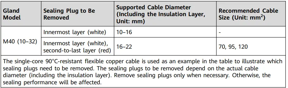
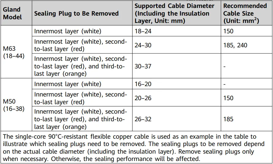
- Remove the cable glands and sealing plugs based on site requirements.

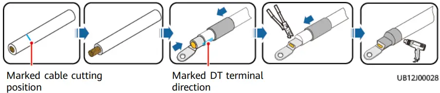
- Cut cables and crimp terminals.
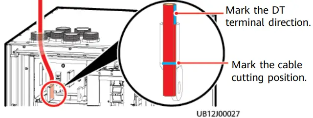
- Measure the cable length and mark the position where a cable needs to be cut and the direction of the DT terminal. (Ensure that the installation surface of the DT terminal is parallel to the copper bar.)

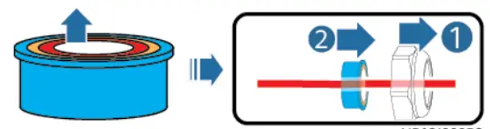
- Remove certain gland sealing plugs. Route the cable through the gland nut and sealing plugs.


- Strip the cable and crimp the DT terminal.

- Measure the cable length and mark the position where a cable needs to be cut and the direction of the DT terminal. (Ensure that the installation surface of the DT terminal is parallel to the copper bar.)
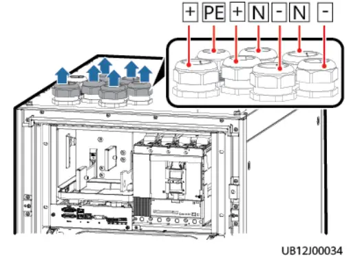
Installing Output Power Cables
- Set the switch based on the actual load.

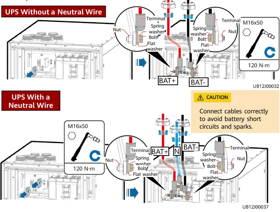
- Install power cables.

- Reinstall the sealing plugs. (The sealing plugs must be completely inserted into the gland to facilitate the reinstallation of the gland nut.)
- Reinstall the gland nut with a torque of 10 N·m (M50) or 12 N·m (M63). Connecting Communications Cables
NOTE
- When reinstalling the communications cable box, prevent the cable box from pressing the cables.
- RS485 cables and FE cables must be shielded cables.
- If more than eight SmartLi cabinets are connected in parallel, a maximum of four 15 m parallel communications cables are supported.
Connecting Communications Cables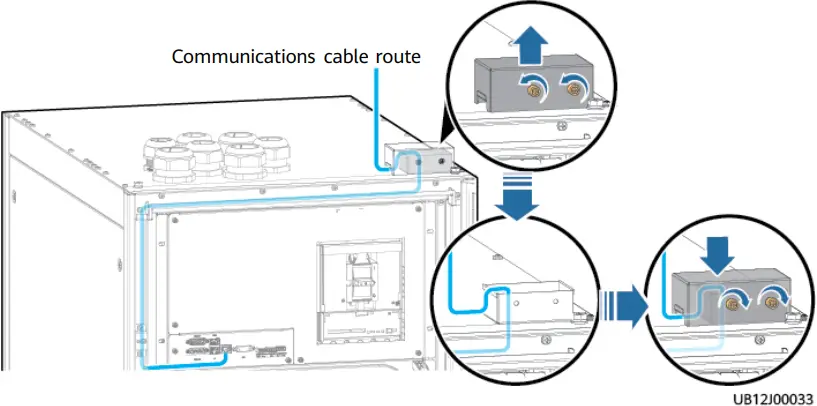
(UPS Communication Involved, Using Three Parallel Cabinets as an Example)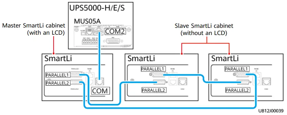
(UPS Communication Not Involved, Using Three Parallel Cabinets as an Example)
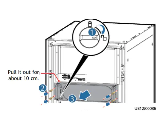
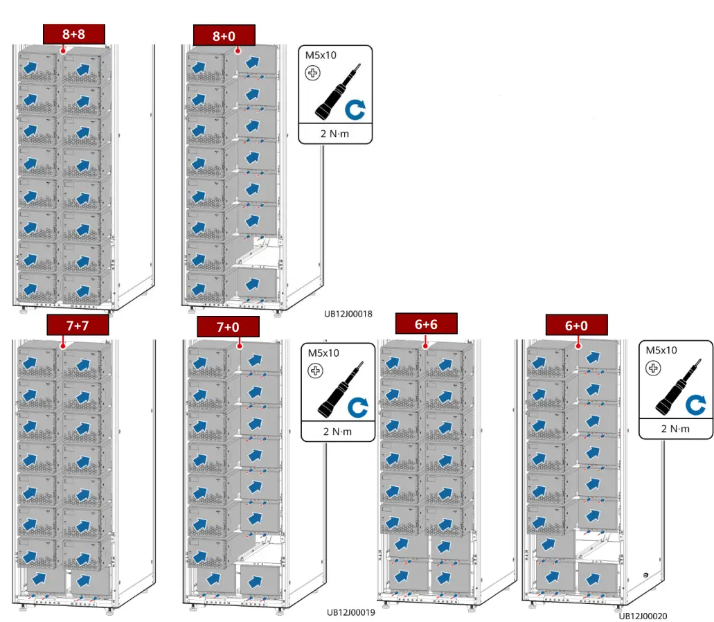
Installing Battery Modules
- Pull out the BCU.

- Install battery modules and filler panels.
DANGER- Do not open the front cover of a battery module when installing or moving it.
- Assign at least three persons or use a lifting trolley to move a battery module. When using a lifting trolley to move a battery module on the aisle, adjust the trolley angle to facilitate installation.
- Install the battery modules from bottom to top and from left to right to prevent falling over due to imbalance.
- If half-capacity cabinet configuration is adopted, battery modules can be installed only on the left side. Install a filler panel at the last but one layer of the right column only after installing battery communications cables.
- Check the insulation performance of the battery modules and secure the modules. (7+7 scenario used as an example)

It is recommended that you use the DC voltage mode of a multimeter to measure the voltage between the ground point and the positive and negative terminals of each battery module respectively. If the readings are less than 6 V DC, the insulation is good. Otherwise, contact technical support engineers.
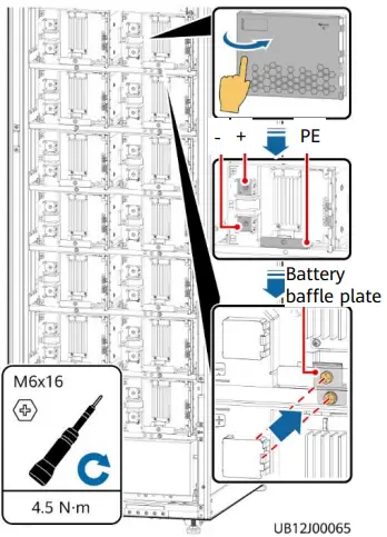
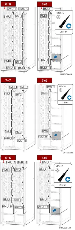
- Install battery communications cables.

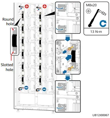
- Install battery copper bars and power cables. (7+7 scenario used as an example)
- Do not open the protective covers for the positive and negative terminals of a battery module at the same time. Close the protective covers for the terminals where copper bars have been installed.
- After removing the safety cap from a power cable, install the cable immediately to prevent the exposed terminal from touching the shell, which may cause sparks or burns.
- Excessive bolts will be used as spare parts.
- When installing cables, ensure that the cables do not block the QR code on the left of the protective cover.
Open the protective covers for the negative terminal of the battery module on the upper layer and the positive terminal of the battery module on the lower layer. Install copper bars between battery modules. Install the copper bar end with a round hole at the battery module on the upper layer, and close the terminal protective cover. Install the copper bar end with a slotted hole at the battery module on the lower layer, and close the terminal protective cover. - Repeat these two steps.

- Open the terminal protective covers, install the battery power cables reserved in the cabinet, and close the terminal protective covers.
- Check the insulation between the battery
strings and the cabinet.
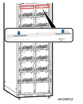
It is recommended that you use the DC voltage mode of a multimeter to measure the voltage between the battery tray and the positive and negative terminals of each battery string respectively. If the readings are less than 6 V DC, the insulation is good. Otherwise, contact technical support engineers. - After checking that the battery strings are well insulated, close the front cover of each battery module. Attach PP sheets to the notches of the battery modules on the top layer to prevent foreign matter from falling into the cabinet. (7+7 scenario used as an example)
NOTE
When attaching PP sheets, align them with the edge of the front cover of battery modules and ensure that the front cover can be opened and closed properly after PP sheets are attached.
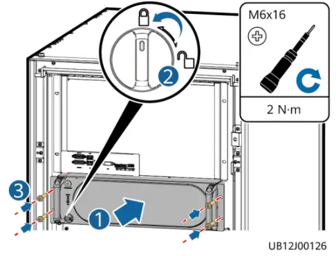
- Reinstall the BCU.

- Select the corresponding model on the nameplate of the cabinet based on the number of installed battery modules. (The figure uses 14 battery modules as an example.)
Verifying the Installation
| Item | Acceptance Criteria |
| Cabinet installation | The cabinet is securely installed and does not tilt due to vibration. |
| Neat arrangement | The adjacent cabinets are neatly arranged and secured with connecting kits. |
| Cable layout | Cables are routed properly as required by the customer. |
| Cable labels | Both ends of a cable are labeled. Labels are concise and easy to understand. |
| Cable ties | Cable ties are secured evenly and no burr exists. |
| Cable or copper bar connections | Battery cables or copper bars are securely connected, the spring washers are crimped properly for cables secured by screws, and the cables are intact. |
| Grounding | The resistance between the cabinet ground bar and the equipment room ground bar is less than 0.1 ohm. |
| Battery cable connections | 1. The cabinet is correctly connected to the UPS. 2. Battery cabinets in parallel are correctly connected. 3. The battery neutral wire (if any) is correctly connected. |
| Short-circuit at the upstream and downstream of circuit breakers | Check whether there is a short circuit between the positive, neutral, and negative cables for circuit breakers, between copper bars, and between the cables, copper bars, and enclosure. If there is a short circuit, check whether the cables are damaged or short-circuited. If yes, repair the cables. |
|
Foreign matter cleaning inside the cabinet | The inside and outside of the cabinet are free from conductive dust or other sundries. 1. There is no foreign matter (such as copper wires and screws) on the top of the cabinet. 2. There is no foreign matter on the copper bar terminals. 3. There is no foreign matter around circuit breaker terminals. 4. There is no foreign matter on the bottom plate of the cabinet. 5. There is no foreign matter on the rear module subrack. |
| Cover installation | All the covers are reinstalled after checks are performed. |
| Storage environment | After the installation is complete, do not store the equipment in an environment where the temperature and humidity are uncontrollable for a long period of time. Otherwise, the equipment may be damaged due to condensation. |
| Insulation resistance of output power cables | The battery cabinet output cables are intact. The insulation resistance of the positive, negative, and neutral output cables to the ground and that between the positive, negative, and neutral output cables are greater than 2 megohms (using a 500 V megohm meter). |
| Installation protection | If batteries are not powered on after installation, take dustproof and anti- condensation measures (for example, using a dust cover, plastic film, or fabric cloth) to prevent battery condensation or dust corrosion. Remove the protective material when batteries need to be used. |
Power-On
NOTE
- Turn on the ready switch on the BCU.
- Ensure that the UPS runs stably in normal mode and the rectifier shown in the energy flow diagram is started.

Communicating with the UPS
The UPS supports communication with SmartLi 3.0 and a communications cable is correctly connected between the UPS and the SmartLi.
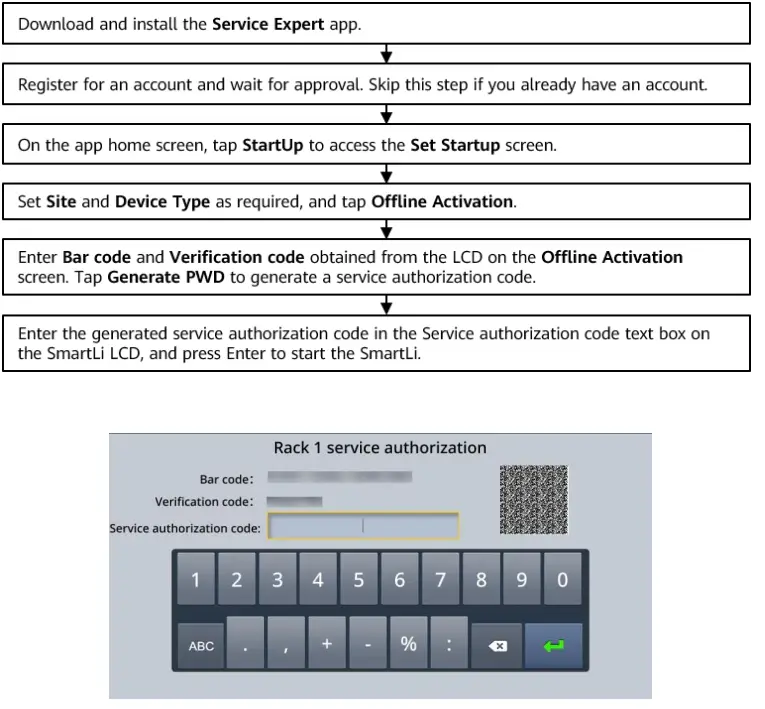
- Press and hold the POWER ON/OFF button on the BCU of the SmartLi cabinet for more than 2s. The green indicator of the BCU blinks at short intervals.
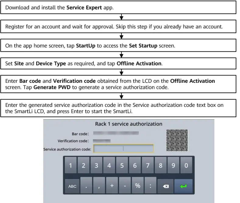
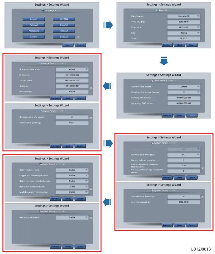
- Obtain authorization on the battery cabinet.

- Set the language, time, date, cloud service, network parameters, system parameters, and alarm parameters on the Settings Wizard screen of the SmartLi.


Item Description Default Value Value Range Application scenario
Specifies the SmartLi connection scenario. Currently, UPS scenarios are
supported.
UPS
UPS, HVDC, EHU, SST
Rated output voltage (V) Specifies the rated output voltage of the battery system. UPS scenario: 512 UPS scenario: 512 Battery cabinet quantity
Specifies the number of battery cabinets connected in parallel. Currently, a maximum of 10 lithium battery cabinets can be connected in parallel. 1
0–10
Cell undervoltage protection threshold (V) You can adjust the end-of- discharge (EOD) threshold as required. 2.7
2.5–2.8
Battery undervoltage protection time (h) Specifies the maximum battery discharge time.
8
8–3000
Maintenance period (y) Specifies the interval for reminding users of battery maintenance. 0 0–10 Last maintained at
After the maintenance is complete, you can set the time as a reference for the next maintenance. First power- on time 2000-01-01 to 2037-12-
31
- On the UPS LCD, choose System Info. > Settings > Battery Settings and set
Battery Type to Lithium battery.
Steady on, switch on the battery circuit breaker on the battery cabinet.
Not Communicating with the UPS
The following operations apply to the scenario where SmartLi 3.0 does not communicate with the UPS (no communications cable is connected between the SmartLi and the UPS).
- On the UPS LCD, choose System Info. > Settings > Battery Settings and set the parameters as follows (the batteries are managed as lead-acid batteries by default. The battery type displayed on the NMS is VRLA batt, but actually lithium batteries are connected to the UPS).
Item Description Setting Battery type Specifies the type of batteries connected to the UPS. VRLA batt. Single battery voltage (V)
Specifies the voltage of each battery that is connected in series in a battery string. 2
12
9999 (maximum value) Single battery capacity (Ah) Specifies the capacity of each battery that is connected in series in a battery string. • If a third-party UPS is connected, set this parameter to the maximum value.
• If the UPS from the Company is connected, set Batt. charging capacity mismatch to Disable on the WebUI.
8+8/8+0 scenario: 8+8/8+0 scenario: Recommended value: Recommended 276 value: 46 Value range: 276–300 Value range: 46–50 7+7/7+0 scenario: 7+7/7+0 scenario: Batteries in a Specifies the number of Recommended value: Recommended battery string batteries in a battery string. 252 value: 42 Value range: 240–270 Value range: 40–45 6+6/6+0 scenario 6+6/6+0 scenario Recommended value: Recommended 204 value: 34 Value range: 192–234 Value range: 32–39 Number of battery strings Specifies the number of battery strings connected in parallel. 1
Cell float voltage (V/cell) Specifies the battery float charging voltage. 2.3 Cell equalized volt. (V/cell)
Specifies the battery equalized charging voltage.
2.3 The UPS from the Company requires that the equalized charging voltage be higher than the float charging voltage, so the equalized charging voltage should be 0.01 V higher. For third-party UPSs, comply with similar requirements if applicable.
Dis. cur. 0.1C EOD (V/cell) Specifies the EOD threshold when the discharge current is 0.1C, 0.3C, 0.5C, or 1.0C respectively.
If a third-party UPS is connected and the EOD is not distinguished by rate, set this parameter to 1.8 V/cell.
1.8
Dis. cur. 0.3C EOD (V/cell) 1.8
Dis. cur. 0.5C EOD (V/cell) 1.75 Dis. cur. 1.0C
EOD (V/cell)
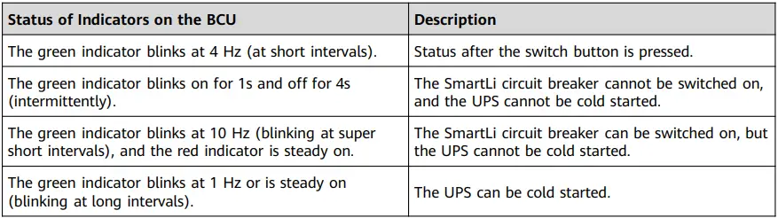
1.75 - Press and hold the POWER ON/OFF button on the BCU of the SmartLi cabinet for more than 2s. The green indicator of the BCU blinks at short intervals.
- The BCB off alarm (the red indicator is steady on) is displayed on the SmartLi LCD. No action is required. After the battery circuit breaker is switched on, the alarm will be automatically cleared. The green indicator blinks intermittently. After 1 minute, the BCU starts. The green indicator blinks at super short intervals and the red indicator is steady on.
If multiple SmartLi cabinets are connected in parallel, press and hold the POWER ON/OFF button on the BCU of the master cabinet for more than 2s to power on the master cabinet. Then, power on slave cabinets one by one in the same way.
- The BCB off alarm (the red indicator is steady on) is displayed on the SmartLi LCD. No action is required. After the battery circuit breaker is switched on, the alarm will be automatically cleared. The green indicator blinks intermittently. After 1 minute, the BCU starts. The green indicator blinks at super short intervals and the red indicator is steady on.
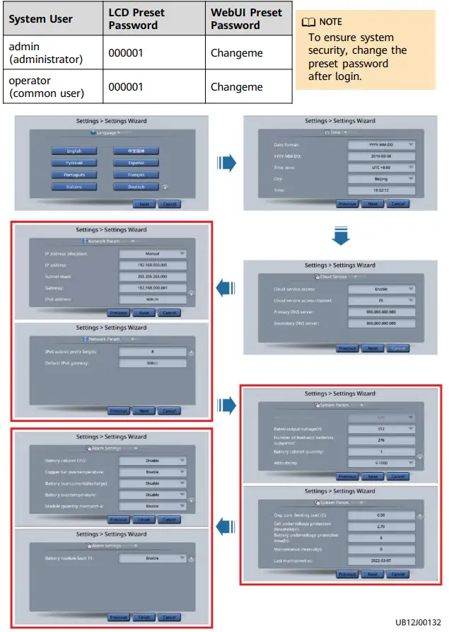
- Obtain authorization on the battery cabinet.

- Set the language, time, date, cloud service, network parameters, system parameters, and alarm parameters on the Settings Wizard screen of the SmartLi.
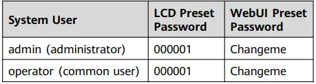
System User LCD Preset Password WebUI Preset Password admin (administrator) 000001 Changeme operator (common user) 000001 Changeme 
Item Description Default Value Value Range Application scenario
Specifies the SmartLi connection scenario. Currently, the UPS and EHU scenarios are supported. UPS
UPS, HVDC, EHU, SST Rated output voltage (V)
Specifies the rated output voltage of the battery system.
UPS scenario: 512
UPS scenario: 512
Number of lead-acid batteries supported (The value of this parameter must be the same as the setting of Batteries in a battery string on the UPS monitoring screen.)
When the SmartLi is connected to the UPS without communication, the UPS manages the SmartLi based on the lead-acid battery logic. You need to set the number of lead- acid batteries supported for the UPS on the SmartLi monitoring screen to ensure that the charge and discharge operating voltage ranges of the UPS and SmartLi match each other. By default, Number of lead-acid batteries supported is set based on the single battery voltage (2 V). If the single battery voltage in the UPS system is 12 V, convert it to 2 V before setting this parameter. For example, if the single battery voltage is 12 V and the number of batteries in a battery string is 42, the value of Number of lead-acid batteries supported is 252 (42 x 12/2 = 252) in the 7+7/7+0 scenario.
8+8/8+0 scenario: 276
8+8/8+0 scenario: 276–
300
7+7/7+0 scenario: 252
7+7/7+0 scenario: 240–
270
6+6/6+0
scenario: 204
6+6/6+0
scenario: 192–
234
Battery cabinet quantity
Specifies the number of battery cabinets connected in parallel. Currently, a maximum of 10 lithium battery cabinets can be connected in parallel.
1
0–10
Altitude (m)
Set this parameter based on the altitude of the place where the rack is used.
≤ 1000
≤ 1000, 1000– 2000, 2000–
3000, 3000–
4000
Chg. cur. limiting coef. (C)
You can set a charge current limit. The limiting coefficient is a multiple of the battery capacity. 0.5
0.05–1.00
Cell undervoltage protection threshold (V) You can adjust the end-of-discharge (EOD) threshold as required. 2.7
2.5–2.8
Battery undervoltage protection time (h) Specifies the maximum battery discharge time. 8
8–3000
Maintenance period (y) Specifies the interval for reminding users of battery maintenance. 0 0–10 Last maintained at
After the maintenance is complete, you can set the time as a reference for the next maintenance. –
–
- After the green indicator of the BCU blinks at super short intervals and the red indicator is steady on, switch on the battery circuit breaker on the battery cabinet.
The preceding procedure applies to the single-cabinet scenario. For the multi-cabinet scenario, see SmartLi 3.0 User Manual (Short-Term Backup Power).
Power-Off
- If battery modules will be stored for a long time after power-off, remove the BCU to reduce battery discharge. This prevents battery modules from being overdischarged due to storage at low SOC.
- If battery modules are stored without being fully charged, charge them according to the requirements in “Operations > Recharge Requirements for Batteries with Low SOC” to prevent battery module damage due to overdischarge.
When you hold the button to power off a cabinet, only the indicators on the cabinet where the software version is later than V500R022C00SPC100 will blink.
Copyright © Huawei Digital Power Technologies Co., Ltd. 2022. All rights reserved.


