SENECA Z-SG Strain Gauge Converter Instruction Manual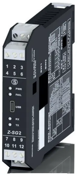
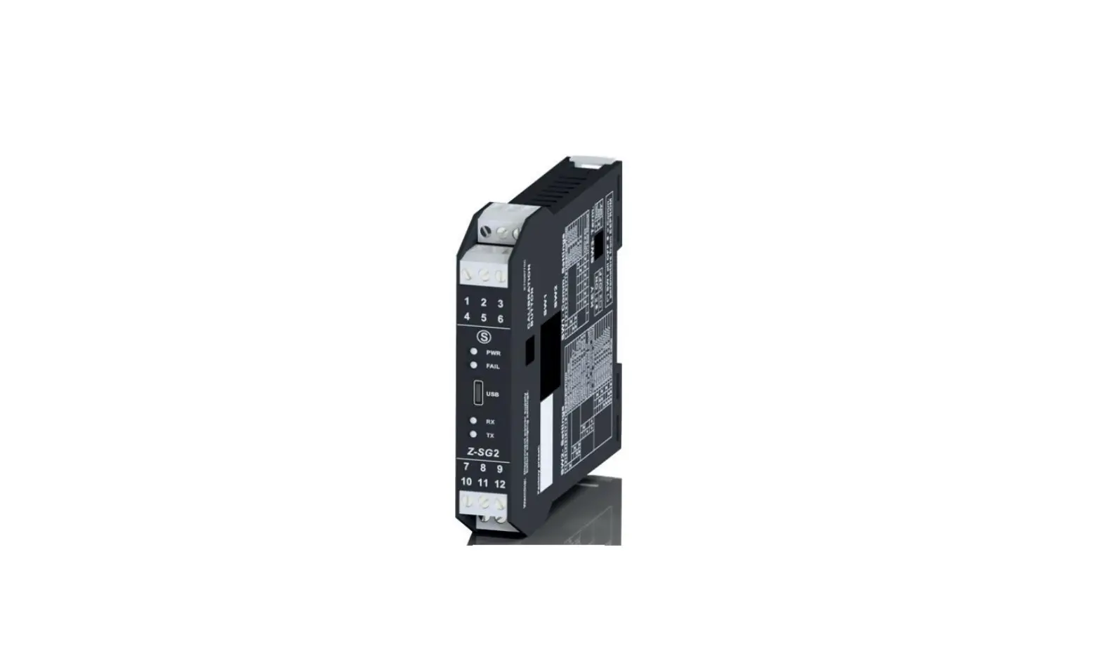
MODULE LAYOUT
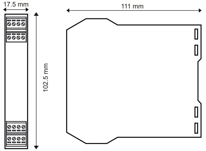
Dimensions LxHxD 17.5 x 102.5 x 111 mm; Weight: 110 g; Enclosure: PA6, black
SIGNALS VIA LED ON FRONT PANEL
| LED | STATUS | LED meaning |
| PWR Green | ON | The device is powered correctly |
| FAIL yellow | On | Faulty |
| RX Red | Flashing | Receipt of packet completed |
| RX Red | ON | Anomaly / Check connection |
| TX Red | Flashing | Transmission of packet completed |
PRELIMINARY WARNINGS
The word WARNING preceded by the symbol ![]() indicates conditions or actions that put the user’s safety at risk. The word ATTENTION preceded by the symbol
indicates conditions or actions that put the user’s safety at risk. The word ATTENTION preceded by the symbol ![]() indicates conditions or actions that might damage the instrument or the connected equipment.
indicates conditions or actions that might damage the instrument or the connected equipment.
The warranty shall become null and void in the event of improper use or tampering with the module or devices supplied by the manufacturer as necessary for its correct operation, and if the instructions contained in this manual are not followed.
![]() WARNING: The full content of this manual must be read before any operation. The module must only be used by qualified electricians. Specific documentation is available at www.seneca.it/products/z-sg2
WARNING: The full content of this manual must be read before any operation. The module must only be used by qualified electricians. Specific documentation is available at www.seneca.it/products/z-sg2
 The module must be repaired and damaged parts replaced by the Manufacturer. The product is sensitive to electrostatic discharges. Take appropriate measures during any operation.
![]() Important: Obstructing ventilation slots with any object is prohibited.
Important: Obstructing ventilation slots with any object is prohibited.
Installing the module next to devices that generate heat is prohibited
 Electrical and electronic waste disposal (applicable in the European Union and other countries with recycling). The symbol on the product or its packaging shows the product must be surrendered to a collection centre authorized to recycle electrical and electronic waste.
![]() ATTENTION: for further information regarding register settings or other details, refer to the USER MANUAL downloadable from www.seneca.it/products/z-sg2
ATTENTION: for further information regarding register settings or other details, refer to the USER MANUAL downloadable from www.seneca.it/products/z-sg2
TECHNICAL SPECIFICATIONS
| STANDARDS | EN61000-6-4 Electromagnetic emissions, industrial environment. EN61000-6-2 Electromagnetic immunity, industrial environment. EN61010-1 Safety |
| INSULATION | 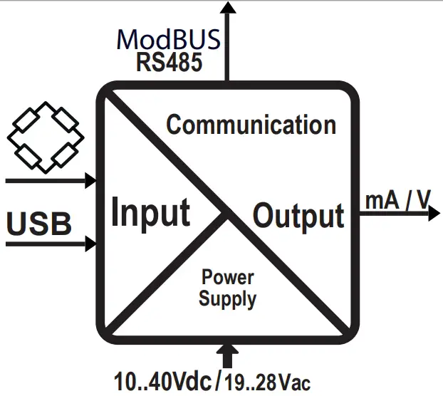 1500 V~ WARNING the maximum working voltage between any terminal and ground must be less than 50 Vac / 75Vdc |
| ENVIRONMENTAL CONDITIONS | Temperature: -10 – + 65°C Humidity: 30%– 90% non condensing. Altitude: up to 2000 m above sea level Storage temperature: -20 + 85° Protection degree: IP20. |
| ASSEMBLY | IEC EN60715, 35mm DIN rail in vertical position. |
| CONNECTIONS | 3-way removable screw terminals, pitch 5 mm Rear connector IDC10 for DIN bar 46277 front micro USB |
| POWER SUPPLY | Voltage: 10 – 40 Vdc; 19 – 28 Vac 50 – 60 Hz Absorption: Typical: 1.5 W @ 24Vdc, Max: 2 W |
| ANALOGUE INPUT | Input type: 4- or 6-wire differential measurement input Input impedance: > 1 MΩ Full scale: ± 10 mV / ± 320 mV Error: 0.01% of the electrical full scale in “factory calibration” mode * Thermal stability: 0.0025%/C° of full scale. Insulation:1500 Vac three-ways |
| COMMUNICATION | Serial communication ports: RS485, 2400 – 115200 Baud / USB 38400 Baud Address: 01, parity: NO, Data: 8 Stop bits: 1 Protocol: Modbus Rtu |
| LOAD CHARACTERISTICS | Supply voltage: 5 VdcMini mum impedance: 87 Ω equivalent (possibly deriving from several load cells) Sensitivity: From ±1 mV/V to ±64 mV/V Load cells: 4 or 6 wires |
| ANALOGUE OUTPUT | Voltage output: Configurable between 0 – 10 Vdc, minimum load resistance 2 kΩ Current input: Configurable between 0 – 20 mA, maximum load resistance: 500 Ω Retransmission error: 0.1 % of maximum field Response time ( 10%..90%): 5 ms |
| DIGITAL IN/OUT | Opto-insulated digital input: Min. voltage: 12 V / Max. voltage: 30 V Opto-insulated digital input: Min. current: 50 mA / Max. voltage: 30 V |
| OTHER SPECIFICATIONS | Input type: 4- or 6-wire differential measurement input Input impedance: > 1 MΩ Full scale: ± 10 mV / ± 320 mV |
* In the case of “calibration with sample weight” mode, the accuracy is given by the linearity error (0.003% of the electric full scale)
DESCRIPTION OF COMMON FUNCTIONS
- Power supply and serial connection wiring facilitated by means of a bus housed in the DIN rail.
- Communication can be configured by DIP-switch or software.
- RS485 serial communication or via USB with MODBUS-RTU protocol.
- Protection against ESD discharges up to 4 kV.
- 1500 Vac insulation: between input and all other circuits, between communication and power supply and between retransmitted output and power supply.
- Analogue output in voltage or current, with programmable limits.
- Cell calibration with sample weight, not required in case of known cell sensitivity.
- Configurable digital I/O.
- Rejection at 50 Hz and 60 Hz.
- Stable weighing signal via digital output/Modbus register.
- Remote tare writing in volatile and/or non-volatile memory via digital input/Modbus register
- Strain gauge directly powered by the instrument.
- Ratiometric measurement.
- Sensitivity from ± 1 to ± 64 mV/V.
- Complete configurability with dedicated EASY SETUP software.
- Cell calibration and configuration using Easy Setup software.
DESCRIPTION OF FUNCTIONS DEDICATED TO THE Z-SG2 INSTRUMENT
- Configurable resolution (max, auto, customized).
- Sampling frequency can be set from 5.4 Hz to 1365.3 Hz.
- Alarm can be activated when a set threshold is exceeded.
- Measurement that can be stabilized by means of a special noise filter.
- Available sizes in both integer and floating point.
- Piece counting function
- Upgradeable firmware.
- Min/max values of the net weight
- Automatic tare reset
SETTING THE SW1 DIP-SWITCHES: Z-SG / Z-SG2 VERSION
The position of the DIP-switches defines the Modbus communication parameters of the module: Address and Baud Rate The following table shows the values of the Baud Rate and the Address according to the setting of the DIP-switches:
DIP-Switch status | |||
SW1 POSITION | BAUD RATE | SW1 POSITION | ADDRESS |
| 1 2 3 4 5 6 7 8 | 1 2 3 4 5 6 7 8 | ||
 | 9600 | #1 | |
 | 19200 | #2 | |
 | 38400 | #… | |
 | 57600 | #63 | |
| From EEPROM | From EEPROM | ||
Note: When DIP switches 3 to 8 are OFF, the communication settings are taken from programming (EEPROM).
SETTING THE SW3 DIP-SWITCHES Z-SG / Z-SG2 VERSION
| Status of the SW3 dip-switches | |||
| SW3 POSITION | SW3 POSITION | ||
| 1 | Ground RS485 | 2 | Terminator RS485 |
| Connected |
| Inserted |
| Disconnected |
| Disengaged |
Note 1: Since the GND terminal of the RS485 port and the negative terminal of the analogue output are not isolated from each other, in order to use the analogue outputs of several instruments simultaneously and connected to each other via the RS485 port, it is necessary to disconnect the GND terminal of the RS485 port via the dedicated dip-switch (SW3).
SETTING THE SW2 DIP-SWITCHES: Z-SG VERSION
SW2 DIP-SWITCH SETTING | |||
| 1 | DIGITAL I/O TYPE + CALIBRATION BUTTON ENABLING | ||
| Selects digital input. Enables calibration button | ||
 | Selects digital output | ||
| 2 | 3 | OUTPUT | |
| 0 – 10 V | |||
 | | 0 – 5 V | |
| 0 – 20 mA | ||
| | 4 – 20 mA | |
| 4 | 5 | METHOD OF USE/CALIBRATION | |
| | Selects how to use 2 and 4 | |
| | Selects how to use 1 and 3 | |
| | Acquisition of the tare value via button or Digital input (2 and 4) | |
| | Manual cell calibration mode (1 and 3) | |
| 6 | 7 | 8 | CELL SENSITIVITY |
| | | ± 1 mV/V |
| | | ± 2 mV/V |
| | | ± 4 mV/V |
| | | ± 8 mV/V |
| | | ± 16 mV/V |
| | | ± 32 mV/V |
| | | Sensitivity from ModBus register SENSE_RATIO (40044). Real non-integer values can also be set. |
ModBUS CONNECTION RULES
- Install the modules in the DIN rail (120 max)
- Connect the remote modules using cables of an appropriate length. The following table shows cable length data:
- Bus length: maximum length of the Modbus network according to the Baud Rate. This is the length of the cables that connect the two farthest modules (see Diagram 1).
- Derivation length: maximum length of a derivation 2 m (see Diagram 1)

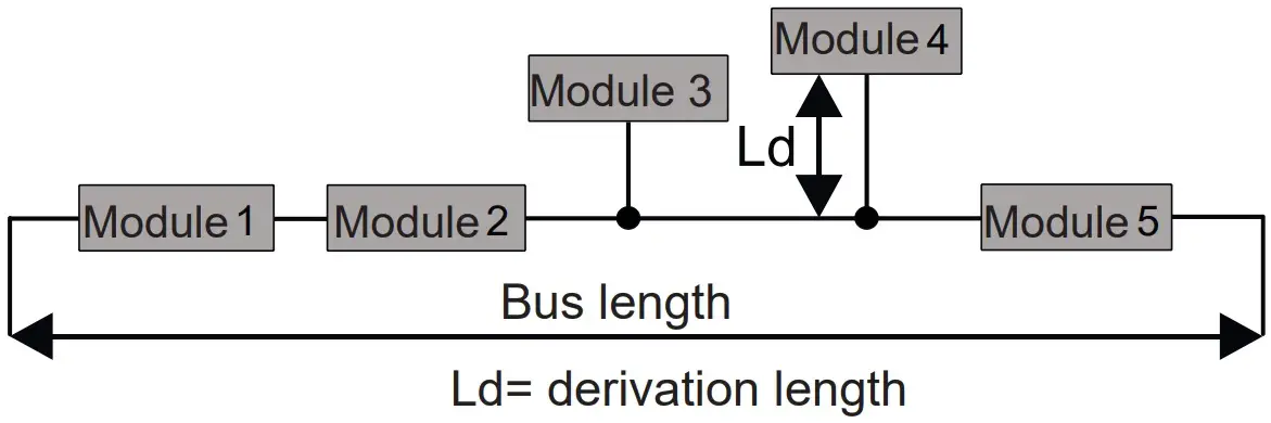
| Bus length | Derivation length |
| 1200 m | 2 m |
For maximum performance, it is recommended to use special shielded cables, such as BELDEN 9841.
INSTALLATION REGULATIONS
The module has been designed for vertical installation on a DIN 46277 rail. For optimal operation and long life, adequate ventilation must be provided. Avoid positioning ducting or other objects that obstruct the ventilation slots. Avoid mounting modules over heat-generating equipment. Installation in the bottom part of the electrical panel is recommended.
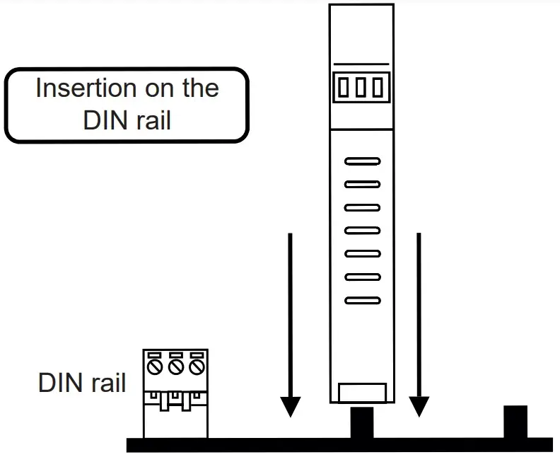
Insertion in the DIN rail
As shown in figure:
- Insert the IDC10 rear connector of the module on a free slot of the DIN rail (the insertion is univocal since the connectors are polarized).
- To secure the module to the DIN rail, tighten the two hooks on the side of the IDC10 rear connector.

USB PORT
The module is designed to exchange data according to the modes defined by the MODBUS protocol. It has a micro USB connector on the front panel and can be configured using applications and/or software programs. The USB communication has priority over the RS485 communication.
The USB serial port uses the communication parameters shown in the table on. The USB communication port responds exactly like the RS485 port with the exception of the communication parameters. During the use of the USB port, the bus will be inactive; it will reactivate automatically after disconnecting the USB port cable. EASY SETUP (for Windows systems) is the software to be used for the configuration and calibration of the load cell. For more information, visit www.seneca.it/products/z-sg or
www.seneca.it/products/sg2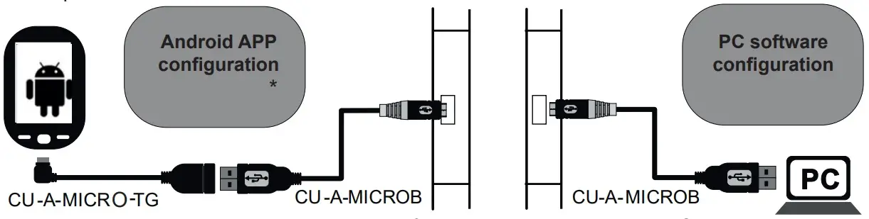
(*) Check that the device in question is included in the list of products supported by the Easy Setup APP in the store.
ELECTRICAL CONNECTIONS
Power supply and Modbus interface are available using the Seneca DIN rail bus, via the IDC10 rear connector, or the Z-PC-DINAL-17.5 accessory.
Back connector (IDC 10)
The illustration shows the meanings of the various IDC10 connector pins if signals are to be sent via them directly.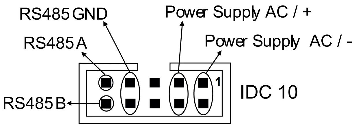
Z-PC-DINAL2-17.5 accessory use
If the Z-PC-DINAL2-17.5 accessory is used, signals can be sent via terminal boards. The illustration shows the meaning of the various terminals and DIP-switch position (found in all supports for the DIN rail listed in Accessories) for the termination of the CAN network (not used for the Modbus network). GNDSHLD:
Connection cable signal protection shield (recommended).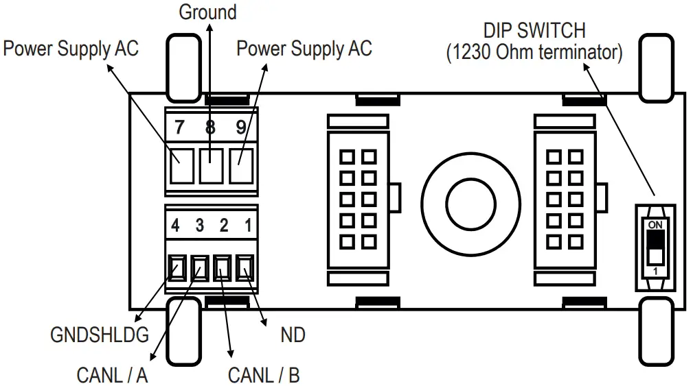
Power supply
Terminals 2 and 3 can be used to provide the module with power supply as an alternative to the connection using the Z-PC-DINx bus. The upper limits must not be exceeded as this can seriously damage the module. If the power supply source is not protected against overload, a safety fuse with a 2.5 max permissible value must be installed in the power supply line.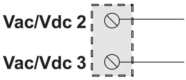
Output
The module provides a retransmitted voltage (configurable in the 0 – 10 Vac range) or current (configurable in the 0 – 20 mA, range) output. For the electrical connections, screened cables are recommended.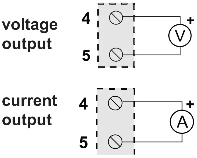
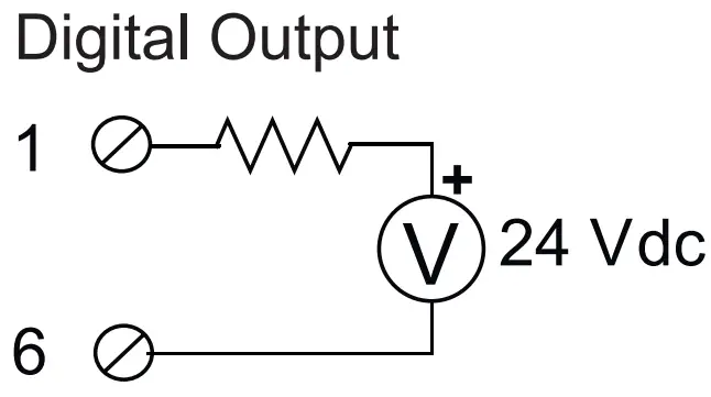
Digital input/output
Depending on the settings, it is possible to decide whether to have a digital output or input. The connections in the two cases are shown below.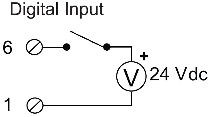
Connection to the load cell via 4 or 6 wires:
The figure shows the connections to be made for a connection to a load cell. The terminals have the following meaning:
- 7: Load cell positive supply
- 8: Load cell positive supply reading
- 9: Cell reading positive
- 10: Load cell negative supply
- 11: Load cell negative supply reading
- 12: Cell reading negative
For the connections, the use of screened cables is required.
4-wire measurement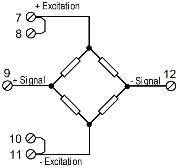
6-wire measurement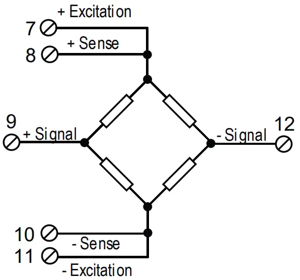
![]() ATTENTION
ATTENTION
The upper power supply limits must not be exceeded, as this might cause serious damage to the module. Switch the module off before connecting inputs and outputs.
To meet the electromagnetic immunity requirements:
- use shielded signal cables;
- connect the shield to a preferential instrumentation earth system;
- separate shielded cables from other cables used for power installations (inverters, motors, induction ovens, etc…).
- Make sure that the power supply voltage to the module does not exceed: 40 Vdc or 28 Vac, otherwise the module will be damaged.
CONFIGURATION OF FACTORY SETTINGS
| All DIP-switches in | OFF position |
| Communication parameters of ModBUS protocol: | 38400 8, N, 1 Address 1 |
| Communication parameters of micro USB front port | 2400 8, N, 1 Address 1 (not configurable) (Z-SG) |
| 38400 8, N, 1 Address 1 (not configurable) (Z-SG) |
FIRMWARE UPDATE MODE (ONLY FOR Z-SG2 VERSION)
To bring the device in Firmware update mode, follow the procedure below:
- Remove power from the device
- Keep the side button pressed
- Power the device keeping the side button pressed
- Wait a few seconds
- Release the side button
To exit the firmware update mode and return to the normal device operation, just:
- Turn off the device
- Power the device without pressing the side button
ACCESSORIES
CODE | DESCRIPTION |
| CU-A-MICROB | USM – micro USB 1 metre communication cable |
| CU-A-MICRO-OTG | Mobile phone adapter cable |
| Z-PC-DINAL2-17.5 | Quick fit support for DIN rail – HEAD + 2 SLOT P = 17.5 mm |
| Z-PC-DIN2-17.5 | Quick fit support for DIN rail – 2 SLOT P = 17.5 mm |
| Z-PC-DIN8-17.5 | Quick fit support for DIN rail – 8 SLOT P = 17.5 mm |
| SG-EQ4 | Equalization and connection system for load cells |
CONTACT INFORMATION
| Technical support | [email protected] | Product information | [email protected] |
This document is the property of SENECA srl. Copies and reproduction are prohibited unless authorised. The content of this document corresponds to the described products and technologies. Stated data may be modified or supplemented for technical and/or sales purposes.
QR Code:

SENECA s.r.l.
Via Austria, 26 – 35127 – PADOVA – ITALY
Tel. +39.049.8705355 – 8705359 – Fax +39.049.8706287
For manuals in other languages and the configuration software, visit www.seneca.it/products/z-sg or www.seneca.it/products/z-sg2
www.logicbus.com
[email protected]
+1 619 616 7350


