![]()
INSTALLATION MANUAL
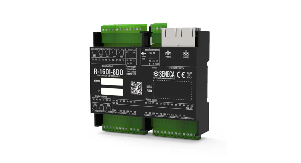
R-32DIDO
R-32DIDO-P
PRELIMINARY WARNINGS
The word WARNING preceded by the symbol![]() indicates conditions or actions that put the user’s safety at risk.
indicates conditions or actions that put the user’s safety at risk.
The word ATTENTION preceded by the symbol ![]() indicates conditions or actions that might damage the instrument or the connected equipment. The warranty shall become null and void in the event of improper use or tampering with the module or devices supplied by the manufacturer as necessary for its correct operation, and if the instructions contained in this manual are not followed.
indicates conditions or actions that might damage the instrument or the connected equipment. The warranty shall become null and void in the event of improper use or tampering with the module or devices supplied by the manufacturer as necessary for its correct operation, and if the instructions contained in this manual are not followed.
 | WARNING: The full content of this manual must be read before any operation. The module must only be used by qualified electricians. Specific documentation is available via QR-CODE shown on page 1. |
 | The module must be repaired and damaged parts replaced by the Manufacturer. The product is sensitive to electrostatic discharges. Take appropriate measures during any operation. |
| Electrical and electronic waste disposal (applicable in the European Union and other countries with recycling). The symbol on the product or its packaging shows the product must be surrendered to a collection center authorized to recycle electrical and electronic waste. |

http://www.seneca.it/products/r-32dido-p
http://www.seneca.it/products/r-32dido
![]()
CONTACT INFORMATION
| Technical support | [email protected] | Product information | [email protected] |
This document is the property of SENECA srl. Copies and reproduction are prohibited unless authorized.
The content of this document corresponds to the described products and technologies.
Stated data may be modified or supplemented for technical and/or sales purposes.
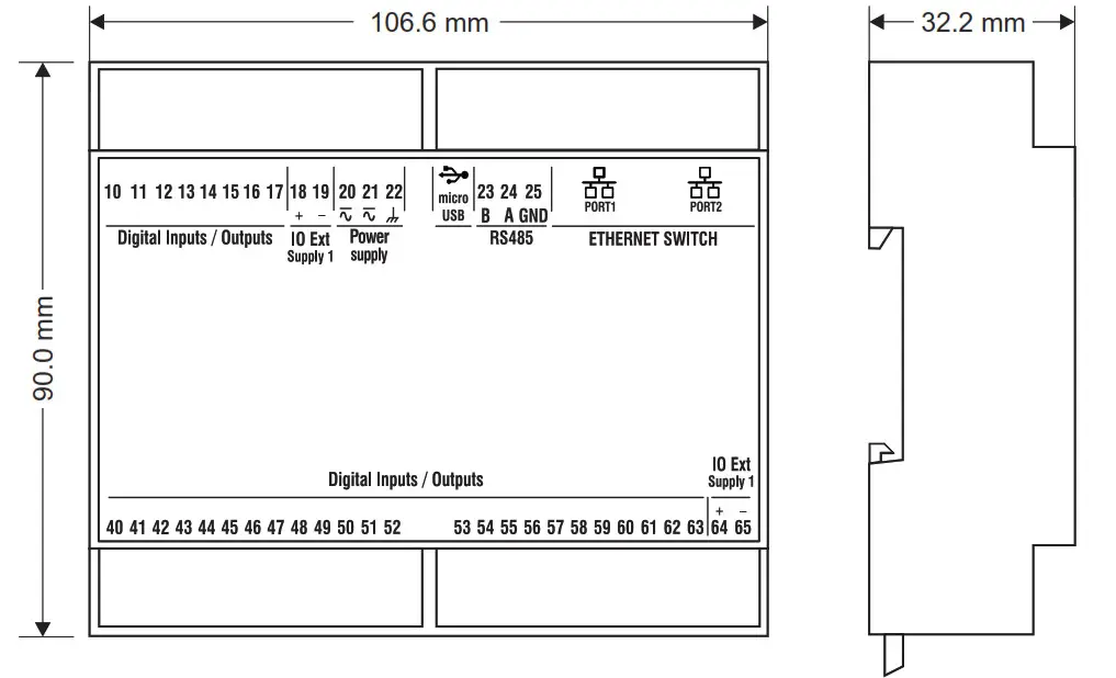
MODULE LAYOUT
Weight: 170 g; Enclosure: UL94-V0 self-extinguishing PC/ABS material, black.
SIGNALS VIA LED ON FRONT PANEL
| LED | STATUS | LED meaning |
| PWR | On | Device powered |
| Off | Device not powered | |
| 101/1032 | On | Digital input/output active |
| Off | Digital input/output not active | |
| OUT SUP | On | Digital inputs/outputs powered |
| Off | Digital inputs/outputs not powered | |
| STS (Status) | On | IP address set |
| Flashing | Waiting for the IP address from the DHCP | |
| COM (R-32DIDO-P version only) | Off | No Profinet communication |
| Flashing | Profinet communication present | |
| FAIL | On | Digital output in FAIL |
| Off | Digital output OK | |
| RX (R-32DIDO version only) | On | RS485 port wiring error |
| Flashing | Reception of data packet completed on RS485 | |
| TX (R-32DID0 version only) | Flashing | Transmission of data packet completed on RS485 |
| ETH TRF (Yellow) | Flashing | Packet transit on Ethernet port |
| ETH LNK (Green) | Flashing | The Ethernet port is connected (LINK) |
TECHNICAL SPECIFICATIONS
| CERTIFICATIONS |   |
| https://www.seneca.it/products/r-32dido/doc/CE_declaration |
| INSULATION | 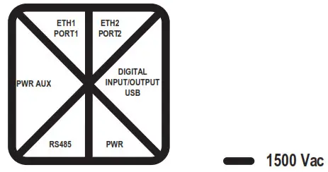 |
| POWER SUPPLY | Voltage: 10+40Vdc; 19+28Vac; 50+65Hz; Absorption: 3W max; Dissipation: 6.5W max |
| ENVIRONMENTAL CONDITIONS | Operating temperature: from -25°C to +65 °C Humidity: 10% + 90% non condensing. Storage temperature: from -30°C to +85 °C Protection rating: IP20 |
| CONFIGURATION | With integrated WEB server (only R-32DID0) / Easy Setup 2 |
| CONNECTIONS / COMMUNICATION PORTS | 3’5 mm pitch terminal block, 1.5 mm2max cable section 1 micro USB port for programming (only R-32DID0) 2 Ethernet (with LAN fault-bypass function) 100 base Ton RJ45 1 RS485 port on terminals 23-24-25 (only R-32DID0 version) |
| DIGITAL INPUTS | Number of channels: 32; Voltage: Threshold ON: >9V; Threshold OFF: <4V; Vmax: 24V; Impedance 91(C) Individually configurable |
| DIGITAL OUTPUTS | Number of channels: 32, MOSFET, PNP; Max voltage/current: 0.2A / 24V Individually configurable |
| COUNTERS | Number of counters: 32 at 32 bits; maximum speed: 50Hz |
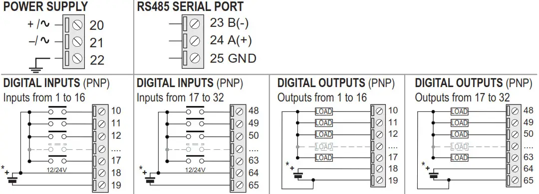
ELECTRICAL CONNECTIONS
![]() CAUTION
CAUTION
Switch the module off before connecting inputs and outputs.
To meet the electromagnetic immunity requirements:
– use shielded signal cables;
– connect the shield to a preferential instrumentation earth system;
– separate shielded cables from other cables used for power installations (transformers, inverters, motors, etc…).
![]() CAUTION
CAUTION
The power supply must be sized according to the expected load at the outputs. Terminals 18-64 and 19-65 can be connected together on the same power supply.![]() CAUTION
CAUTION
*For correct operation of the instrument, terminals 18-64 and 19-65 must always be connected to the power supply.
DAISY-CHAIN ETHERNET CONNECTION
![]() CAUTION
CAUTION
IT IS NOT ALLOWED TO CREATE LOOPS WITH ETHERNET CABLES
Using the daisy-chain connection it is not necessary to use switches to connect the devices.
The following examples show the correct connections.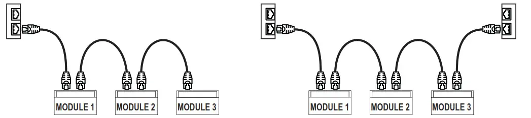
There must be no loops in the Ethernet cabling, otherwise, the communication will not work. The modules and switches must be connected eliminating any loops. The following examples show the incorrect connections.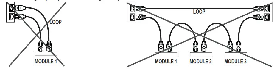
The LAN fault-bypass function allows you to keep the connection between the two Ethernet ports of the device ON, in the event of a power failure. If a device turns off, the chain is not interrupted and the devices downstream of the switched-off one will still be accessible. This function has a limited duration: the connection remains active for a few days, typically 4. The fault-bypass function requires that the sum of the lengths of the two cables connected to the switched-off module is less than 100m.
ETHERNET CONNECTION RULES
For the Ethernet cabling between the devices, the use of the unshielded CAT5 or CAT5e cable is required.
CAT6 for industrial environments.
FACTORY IP ADDRESS
The default module IP address is static: 192. 168. 90. 101
WEBSERVER
To access the maintenance Web Server with the factory IP address above, use the following credentials:
Account User: admin; Password: admin
![]() CAUTION
CAUTION
DO NOT USE DEVICES WITH THE SAME IP ADDRESS IN THE SAME ETHERNET NETWORK.
SETTING THE DIP-SWITCHES
The DIP-SWITCH on the back of the device has the following function:
SW1 DIP-SWITCH: DEFAULT SETTINGS
| SW1 | ||
| DIP1 | ON | DEFAULT SETTINGS |
| DIP2 | ON | |
To access the DIP-SWITCH it is necessary to remove the bottom of the instrument.


