YAMAHA MLC200 Music Laboratory Controller Installation Guide
Introduction
Customer Support
If you need assistance at any time during installation or when the MLC-200 system is in use, please contact Yamaha
Customer Support at 714-522-9011 and when prompted to choose a support department, enter code 44.
Overview
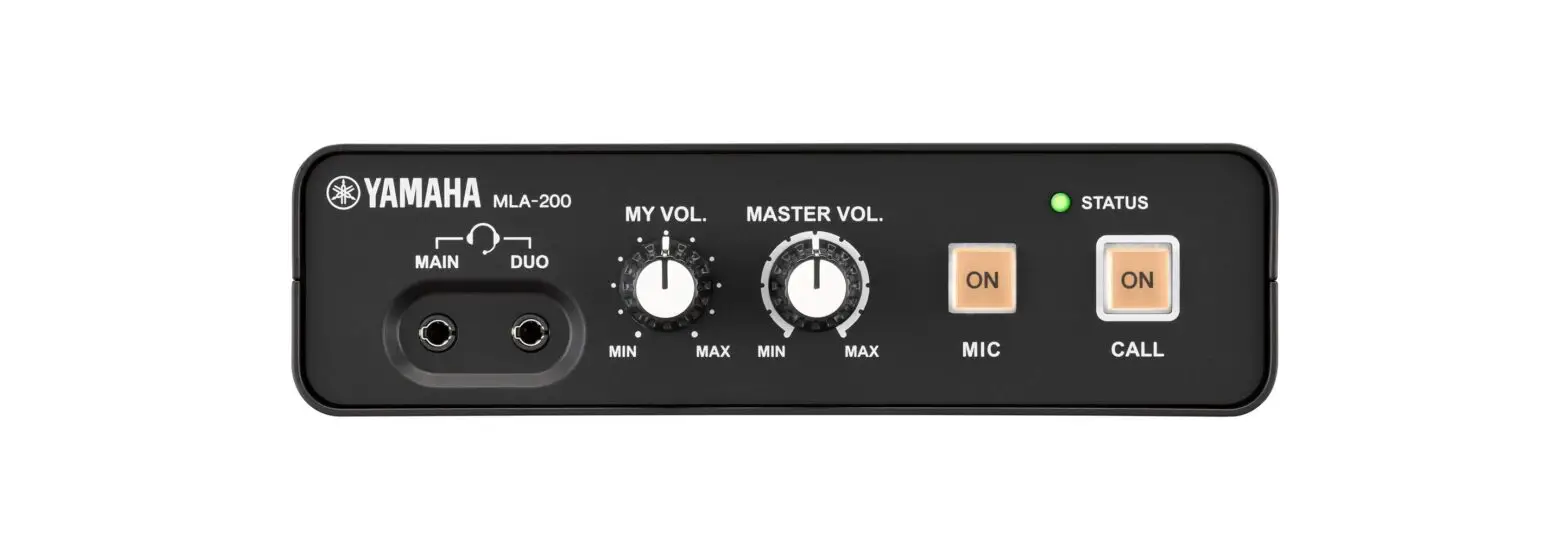
The Yamaha Music Laboratory Controller is a music education system that combines Yamaha know-how in music education and electronics technology. This system is built to support communication between students and instructors and to provide more fluid guidance on individual and group performances. Instructors use the ML Touch application on an iPad to operate the entire system, such as checking students’ performances, responding to questions and sending performance data.
This system combines MRX7-D as the core of the audio network and MLA 200 (with a master unit for the instructor and subordinate units for the students). Up to 24 subordinate units for students can be connected to one MRX7-D. At maximum, a system can be built to connect 96 subordinate units with four MRX7-Ds.
This Setup Guide provides the necessary information for building and setting up the MLC-200 in a classroom. We recommend that you read this information before and during setup.
Preparations
Items necessary for building the system
| MLA-200 | One for the instructor and a maximum of 96 for students. |
| MRX7-D | A maximum of one MLA-200 for the instructor and 24 MLA-200s for students can be connected to one MRX7-D. Up to four MRX7-Ds can be connected. |
| PoE powered Ethernet switch | A power supply of 6 W or more per port is required. |
| Ethernet cable | STP CAT5e (1000BASE-T) or higher grade STP cables are required. Prepare a total number of cables equal to the number of MLA-200s + the number of MRX7-Ds × 2 + the computer + the wireless access point + the Ethernet switch. |
| USB cable (Type AB) | Use to communicate MIDI data with the instrument. Prepare the same number as MLA-200s. |
| Audio cable | Use to connect the instrument and MLA-200. Prepare stereo cables with standard headphones plugs. |
| Headphones/microphone headset | With 3.5 mm mini plugs (CTIA compliant). |
| Wireless access point/DHCP server | Use for communication between the iPad application and the hardware. This device must be able to perform the DHCP server function of assigning addresses to both wireless devices and LAN devices. |
| Audio playback device (optional) | Use Audio/Video Device, etc., to play back audio teaching materials. |
| Microphone (optional) | For audio input by the instructor. |
| iPad | Use to operate the “ML Touch” control application for the instructor. iOS 12 or later is required. |
| ML Touch | This iPad application for instructors can be obtained for free from the App Store. |
Items necessary only for setup
| Windows computer | Use to specify settings during setup. A computer with an RJ-45 connector and running Windows 10, Windows 8.1 or Windows 7 is required. |
| ML Config Tool | This software automatically configures the audio network connection between the MRX7-Ds and MLA-200s. Install this software on a Windows computer. |
| Dante Controller | Use to change the audio network setup manually (for special settings) and to check the status of the system |
Workflow
Follow the workflow below to build and set up the Music Laboratory System.
- Trial setup
- Setting up the wireless access point (DHCP server)
- Setting up MLA-200s
- Setting up MRX7-Ds
- Setting up the audio network
- Setting up ML Touch
- Connecting audio devices
- Operation check
- Installing the MLA-200 onto the instrument
- Final operation check
Trial setup
Before installing the devices in the classroom, perform a trial setup of the entire system to check the setup and operation of each device.
Since it will be difficult to remove and attach the DIP switch cover and change the DIP switch settings after the MLA-200 is installed onto an instrument, we recommend checking the setup and operation of each device prior to installation on the instrument.
Setting up the wireless access point (DHCP server)
The “ML Touch” application for the instructor communicates with each device via Wi-Fi. For that reason, the network must include a wireless access point.
The wireless access point used here must be able to perform the DHCP server function of assigning addresses to both wireless devices and LAN devices.
Connect the wireless access point to the Windows computer, and then set it up.
Connect the computer and wireless access point with an Ethernet cable.
Check IP Settings of the Computer
Select “Obtain an IP address automatically” in the “Internet Protocol Version 4 (TCP/IPv4) Properties” dialog box of “Network and Sharing Center” in the Windows Control Panel.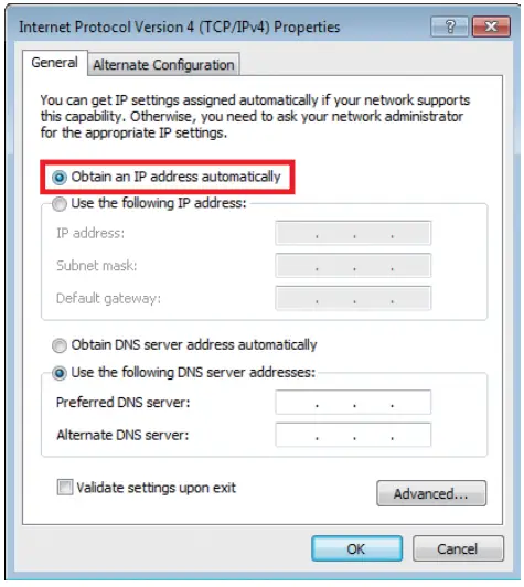
After selecting the setting, click the “OK” button.
This completes the network setup of the PC.
Setting up MLA-200s
Each MLA-200 in an audio network is differentiated by the unique ID that is specified.
Specify this ID with the DIP switch.
With nothing connected, open the DIP switch cover on the rear panel.
One side of the cover remains attached. Disengage the side that does not remain attached, and then slowly open the cover.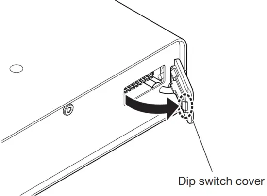
Set the DIP switch
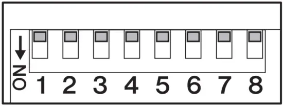
The switches of the DIP switch are set to ON when it is down and OFF when it is up.
As a default, all switches are set to OFF (up).
NOTE
Be sure to view the DIP switch in its proper orientation.
Set the DIP switch for each MLA-200 according to the following tables.
Visit Yamaha.io/MLA200Setup or scan the QR code below to utilize our MLA-200 Student Number Helper for DIP Switch Settings.

Instructor and students 1 to 24 (MRX7-D ID=1)
| SW | ||||||||
| 1 | 2 | 3 | 4 | 5 | 6 | 7 | 8 | |
| Instructor | OFF | OFF | OFF | OFF | OFF | OFF | OFF | ON |
| Student 1 | OFF | OFF | OFF | OFF | OFF | OFF | ON | OFF |
| Student 2 | OFF | OFF | OFF | OFF | OFF | OFF | ON | ON |
| Student 3 | OFF | OFF | OFF | OFF | OFF | ON | OFF | OFF |
| Student 4 | OFF | OFF | OFF | OFF | OFF | ON | OFF | ON |
| Student 5 | OFF | OFF | OFF | OFF | OFF | ON | ON | OFF |
| Student 6 | OFF | OFF | OFF | OFF | OFF | ON | ON | ON |
| Student 7 | OFF | OFF | OFF | OFF | ON | OFF | OFF | OFF |
| Student 8 | OFF | OFF | OFF | OFF | ON | OFF | OFF | ON |
| Student 9 | OFF | OFF | OFF | OFF | ON | OFF | ON | OFF |
| Student 10 | OFF | OFF | OFF | OFF | ON | OFF | ON | ON |
| Student 11 | OFF | OFF | OFF | OFF | ON | ON | OFF | OFF |
| Student 12 | OFF | OFF | OFF | OFF | ON | ON | OFF | ON |
| Student 13 | OFF | OFF | OFF | OFF | ON | ON | ON | OFF |
| Student 14 | OFF | OFF | OFF | OFF | ON | ON | ON | ON |
| Student 15 | OFF | OFF | OFF | ON | OFF | OFF | OFF | OFF |
| Student 16 | OFF | OFF | OFF | ON | OFF | OFF | OFF | ON |
| Student 17 | OFF | OFF | OFF | ON | OFF | OFF | ON | OFF |
| Student 18 | OFF | OFF | OFF | ON | OFF | OFF | ON | ON |
| Student 19 | OFF | OFF | OFF | ON | OFF | ON | OFF | OFF |
| Student 20 | OFF | OFF | OFF | ON | OFF | ON | OFF | ON |
| Student 21 | OFF | OFF | OFF | ON | OFF | ON | ON | OFF |
| Student 22 | OFF | OFF | OFF | ON | OFF | ON | ON | ON |
| Student 23 | OFF | OFF | OFF | ON | ON | OFF | OFF | OFF |
| Student 24 | OFF | OFF | OFF | ON | ON | OFF | OFF | ON |
Students 25 to 48 (MRX7-D ID=2)
| SW | ||||||||
| 1 | 2 | 3 | 4 | 5 | 6 | 7 | 8 | |
| Student 25 | OFF | OFF | OFF | ON | ON | OFF | ON | OFF |
| Student 26 | OFF | OFF | OFF | ON | ON | OFF | ON | ON |
| Student 27 | OFF | OFF | OFF | ON | ON | ON | OFF | OFF |
| Student 28 | OFF | OFF | OFF | ON | ON | ON | OFF | ON |
| Student 29 | OFF | OFF | OFF | ON | ON | ON | ON | OFF |
| Student 30 | OFF | OFF | OFF | ON | ON | ON | ON | ON |
| Student 31 | OFF | OFF | ON | OFF | OFF | OFF | OFF | OFF |
| Student 32 | OFF | OFF | ON | OFF | OFF | OFF | OFF | ON |
| Student 33 | OFF | OFF | ON | OFF | OFF | OFF | ON | OFF |
| Student 34 | OFF | OFF | ON | OFF | OFF | OFF | ON | ON |
| Student 35 | OFF | OFF | ON | OFF | OFF | ON | OFF | OFF |
| Student 36 | OFF | OFF | ON | OFF | OFF | ON | OFF | ON |
| Student 37 | OFF | OFF | ON | OFF | OFF | ON | ON | OFF |
| Student 38 | OFF | OFF | ON | OFF | OFF | ON | ON | ON |
| Student 39 | OFF | OFF | ON | OFF | ON | OFF | OFF | OFF |
| Student 40 | OFF | OFF | ON | OFF | ON | OFF | OFF | ON |
| Student 41 | OFF | OFF | ON | OFF | ON | OFF | ON | OFF |
| Student 42 | OFF | OFF | ON | OFF | ON | OFF | ON | ON |
| Student 43 | OFF | OFF | ON | OFF | ON | ON | OFF | OFF |
| Student 44 | OFF | OFF | ON | OFF | ON | ON | OFF | ON |
| Student 45 | OFF | OFF | ON | OFF | ON | ON | ON | OFF |
| Student 46 | OFF | OFF | ON | OFF | ON | ON | ON | ON |
| Student 47 | OFF | OFF | ON | ON | OFF | OFF | OFF | OFF |
| Student 48 | OFF | OFF | ON | ON | OFF | OFF | OFF | ON |
Students 49 to 72 (MRX7-D ID=3)
| SW | ||||||||
| 1 | 2 | 3 | 4 | 5 | 6 | 7 | 8 | |
| Student 49 | OFF | OFF | ON | ON | OFF | OFF | ON | OFF |
| Student 50 | OFF | OFF | ON | ON | OFF | OFF | ON | ON |
| Student 51 | OFF | OFF | ON | ON | OFF | ON | OFF | OFF |
| Student 52 | OFF | OFF | ON | ON | OFF | ON | OFF | ON |
| Student 53 | OFF | OFF | ON | ON | OFF | ON | ON | OFF |
| Student 54 | OFF | OFF | ON | ON | OFF | ON | ON | ON |
| Student 55 | OFF | OFF | ON | ON | ON | ON | OFF | OFF |
| Student 56 | OFF | OFF | ON | ON | ON | ON | OFF | ON |
| Student 57 | OFF | OFF | ON | ON | ON | ON | ON | OFF |
| Student 58 | OFF | OFF | ON | ON | ON | ON | ON | ON |
| Student 59 | OFF | OFF | ON | ON | ON | ON | OFF | OFF |
| Student 60 | OFF | OFF | ON | ON | ON | ON | OFF | ON |
| Student 61 | OFF | OFF | ON | ON | ON | ON | ON | OFF |
| Student 62 | OFF | OFF | ON | ON | ON | ON | ON | ON |
| Student 63 | OFF | ON | OFF | OFF | OFF | OFF | OFF | OFF |
| Student 64 | OFF | ON | OFF | OFF | OFF | OFF | OFF | ON |
| Student 65 | OFF | ON | OFF | OFF | OFF | OFF | ON | OFF |
| Student 66 | OFF | ON | OFF | OFF | OFF | OFF | ON | ON |
| Student 67 | OFF | ON | OFF | OFF | OFF | ON | OFF | OFF |
| Student 68 | OFF | ON | OFF | OFF | OFF | ON | OFF | ON |
| Student 69 | OFF | ON | OFF | OFF | OFF | ON | ON | OFF |
| Student 70 | OFF | ON | OFF | OFF | OFF | ON | ON | ON |
| Student 71 | OFF | ON | OFF | OFF | ON | OFF | OFF | OFF |
| Student 72 | OFF | ON | OFF | OFF | ON | OFF | OFF | ON |
Students 73 to 96 (MRX7-D ID=4)
| SW | ||||||||
| 1 | 2 | 3 | 4 | 5 | 6 | 7 | 8 | |
| Student 73 | OFF | ON | OFF | ON | ON | OFF | ON | OFF |
| Student 74 | OFF | ON | OFF | ON | ON | OFF | ON | ON |
| Student 75 | OFF | ON | OFF | ON | ON | ON | OFF | OFF |
| Student 76 | OFF | ON | OFF | ON | ON | ON | OFF | ON |
| Student 77 | OFF | ON | OFF | ON | ON | ON | ON | OFF |
| Student 78 | OFF | ON | OFF | ON | ON | ON | ON | ON |
| Student 79 | OFF | ON | OFF | ON | OFF | OFF | OFF | OFF |
| Student 80 | OFF | ON | OFF | ON | OFF | OFF | OFF | ON |
| Student 81 | OFF | ON | OFF | ON | OFF | OFF | ON | OFF |
| Student 82 | OFF | ON | OFF | ON | OFF | OFF | ON | ON |
| Student 83 | OFF | ON | OFF | ON | OFF | ON | OFF | OFF |
| Student 84 | OFF | ON | OFF | ON | OFF | ON | OFF | ON |
| Student 85 | OFF | ON | OFF | ON | OFF | ON | ON | OFF |
| Student 86 | OFF | ON | OFF | ON | OFF | ON | ON | ON |
| Student 87 | OFF | ON | OFF | OFF | ON | OFF | OFF | OFF |
| Student 88 | OFF | ON | OFF | OFF | ON | OFF | OFF | ON |
| Student 89 | OFF | ON | OFF | OFF | ON | OFF | ON | OFF |
| Student 90 | OFF | ON | OFF | OFF | ON | OFF | ON | ON |
| Student 91 | OFF | ON | OFF | OFF | ON | ON | OFF | OFF |
| Student 92 | OFF | ON | OFF | OFF | ON | ON | OFF | ON |
| Student 93 | OFF | ON | OFF | OFF | ON | ON | ON | OFF |
| Student 94 | OFF | ON | OFF | OFF | ON | ON | ON | ON |
| Student 95 | OFF | ON | ON | OFF | OFF | OFF | OFF | OFF |
| Student 96 | OFF | ON | ON | OFF | OFF | OFF | OFF | ON |
Setting up MRX7-Ds
For details on Labs greater than 24 students, please contact Yamaha Customer Support at 714.522.9011 and when prompted to choose a support department, enter code 44 for assistance and important configuration downloads.
Before turning on MRX7-D, set the rotary switch and DIP switch.
Specify the following settings.
MRX7-D ID=1 (instructor and students 1 to 24)
Rotary switch=1, DIP switch=All switches set to OFF (up)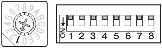
Setting up the Dante Audio Network
Communications between the instructor and students as well as audio of the performance is sent and received through the audio network. In the MLC200 Music Laboratory System, Dante has been adopted as the structure of the audio network. Although software called Dante Controller is normally used to set up a Dante audio network, its high degree of flexibility requires knowledge about audio networks.
Therefore, the dedicated software ML Config Tool is used in the MLC200 Music Laboratory System to make setup easier.
Download the ML Config Tool Software here: Yamaha.io/MLCdownloads
Connect all MLA-200s to Ethernet switches.
The [STATUS] indicator flashes while the device is starting up. The indicator lights up when the device is finished starting up.
Check that the [STATUS] indicator of all MLA-200s are lit.
Connection diagram showing 8 students.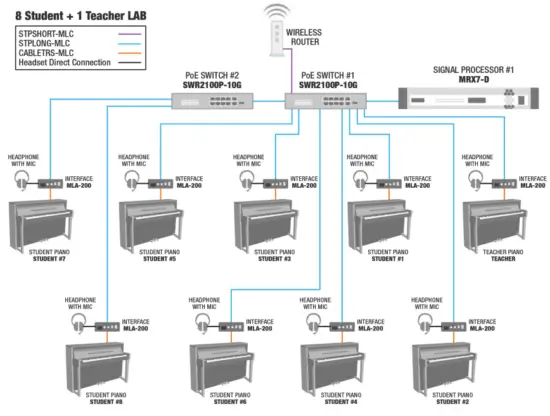
Connection diagram showing 15 students.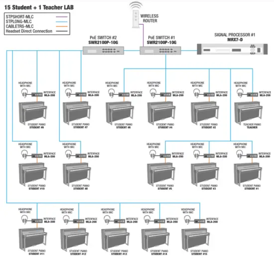
NOTE
- Before making connections, be sure to complete the procedure in “3. Setting up MLA-200s” (Page 6).
The changes to the DIP switch settings are applied when the Ethernet cable is connected and the MLA-200 is turned on. Before changing the settings, unplug the Ethernet cable from the MLA-200.
Connection diagram showing 24 students.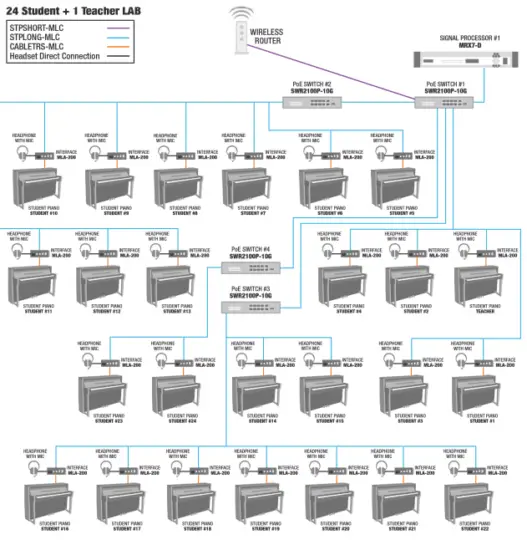
Start the ML Config Tool installed onto the Windows computer.
A window appears. Follow on screen steps to set up the Lab System.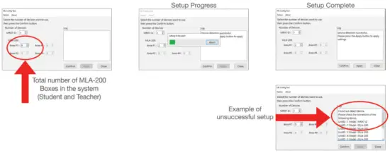
In “The number of MLA-200” box, type the number of MLA-200s connected
Include the MLA-200 for the instructor with the number of devices for Area #1. Area #1 can be set between 2 (for 1 instructor + 1 student) and 25 (for 1 instructor + 24 students); Area #2 to #4 can be set between 1 (for 1 student) and 24 (for 24 students).
Click the “Confirm” button.
The software automatically checks that the MRX7-Ds and MLA-200s are correctly set up. If they are correctly set up, “Succeed” appears in the “Output” box on the right side of the window. If this does not appear, return to the previous steps and check each of the settings.
Check that “Succeed” appears, and then click the “Apply” button.
This completes the setup of the audio network.
Setting up ML Touch
ML Touch is an iPad application used by instructors to operate the entire system.
It can be downloaded from the App Store.
This describes the setup operations that must be performed before the application can be used. For details on using ML Touch, refer to the ML Touch User’s Guide.
Scan here to download from the app store.
Download ML Touch from the App Store.
Tap the ML Touch icon to start the application.
The initial setup window appears.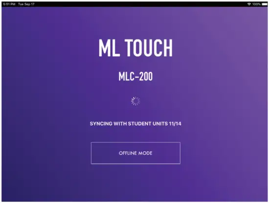
Next: The Home Window should appear. If an error appears, check the following:
- Are the MLA-200s connected correctly and are there no duplicate Unit IDs?
If an error appeared, the Home window does not appear. Force quit ML Touch app and relaunch.
If the iPad is not connected via Wi-Fi adjust settings in iOS. Refer to Step 7 in the Quick Setup Guide.
This completes the setup of ML Touch.
Connecting optional audio devices
Connect audio devices, such as the instructor’s microphone or Audio/Video Device used for teaching, to the MRX7-D set to ID=1.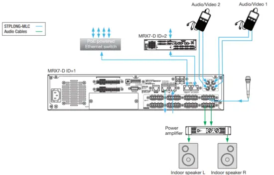
NOTE
Use the Euroblock connectors on the MRX7-D to make the microphone input and speaker output connections.
Turn off all devices to be connected.
Connect the audio devices as shown above.
Use the Euroblock connectors on the MRX7-D to make connections for the microphone input and power amplifier (powered speakers). For details on using the Euroblock connectors, refer to “Euroblock plug connection” in the MRX7-D Owner’s Manual.
When using multiple MRX7-Ds, connect via YDIF ports.
Turn on the MRX7-D.
When using multiple MRX7-D, turn on in order, starting with ID=1.
Turn on the power amplifier (powered speakers).
Start ML Touch.
Adjust the volume of the power amplifier.
At this time, adjust the volume to check that the connection has been made. If no sound is heard from the speakers, return to the previous steps and perform each one again. This completes the connection of the audio devices.
Operation check
Refer to page 10 of Quick Setup Guide for Testing and Troubleshooting.
Installing onto an instrument (optional)
After performing the operation check, unplug all cables connected to the MLA-200s, and then install the MLA-200 onto the instrument.
The MLA-200 can be installed in the following two ways:
- Attaching to the instrument with the included mounting screws
- Placing on a flat surface of the instrument with the included rubber feet
Installation precautions (attaching to the instrument with included screws)
- Install so that the cables on the side panel face downward
- Install so that there is no interference with headphones or connectors on the instrument
- Install so that the knobs of the MLA-200 and connected cables do not extend past the body of the instrument
- Be careful not to trip over connected cables while performing operations
- Be sure to use the included screws for the installation
- In order to prevent wood parts of the instrument from cracking, install the screws at least 15 mm inside the edge of the leg or stand of the instrument onto which the MLA-200 is mounted
Installation procedure
Attach the mounting bracket to the MLA-200
Use the included mounting screws for installing the product.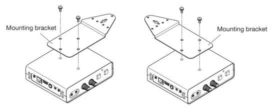
While holding the MLA-200 in the desired position, drill four holes (for attaching the mounting bracket) into the instrument’s stand (leg).
Drill holes with a depth of 15 mm and diameter of 2.5 mm at the center of the screw holes, positioned at least 15 mm inside the edge of the stand (leg). Be careful not to drill the holes too deep. In addition, be sure to drill all four holes.
NOTE
If the exterior of the instrument has a polished (mirror) finish, also countersink the holes to about 6 to 6.5 mm in diameter.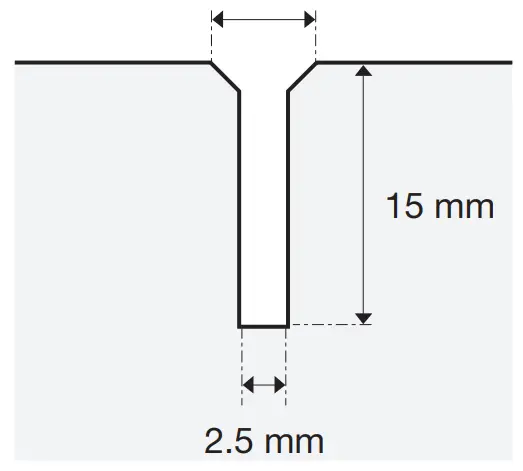
Drive in the center screw about halfway.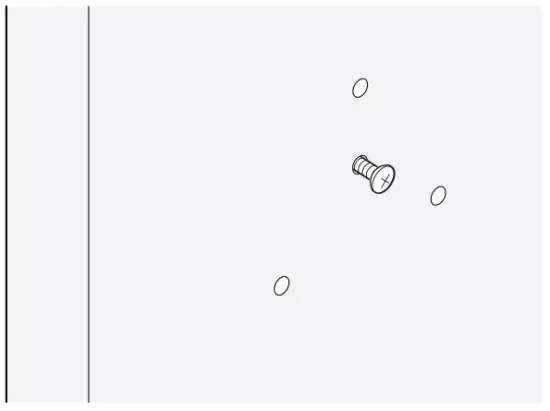
Hook the guide hole at the center of the mounting bracket onto the center screw.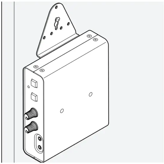
Install and tighten the other screws.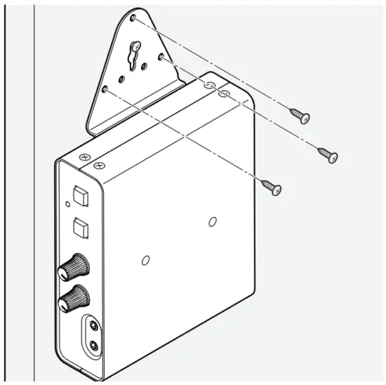
Tighten the center screw last.
Make sure that all screws are properly tightened.
This completes the installation onto the instrument.
Installation examples
Mounted with screws at the top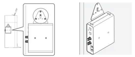
This is the most common installation method. Use this method when the stand (leg) of the instrument is wide.
Mounted with screws on the side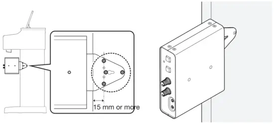
Use this installation method when the instrument stand is toward the back of the keyboard.
As described in “Installation precautions (attaching to the instrument with included screws)” (Page 18), maintain a distance of 15 mm or more between the center screw and the edge of the stand, and install by using all four screws.
Mounted with screws at the bottom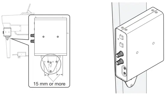
If the instrument has a thin stand, mount the MLA-200 with the screws at the top, or at the bottom using this installation method. With this method, also maintain a distance of 15 mm or more between the center screw and the edge of the stand, and install by using all four screws, as described in “Installation precautions (attaching to the instrument with included screws)” (Page 18).
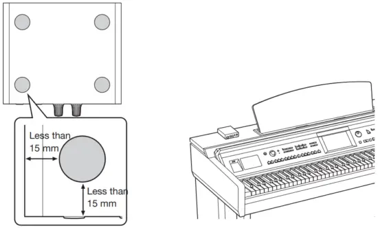
When placed on a flat surface
When placed on a flat surface of the instrument, be sure to attach the included rubber feet to prevent slipping.
The installation positions should be about 15 mm inside each edge as shown below. Be sure to attach all four.
![]() Caution
Caution
Position the MLA-200 so that no one will trip and nothing will catch on the cables.
If the MLA-200 falls, it may be damaged or cause injuries.
Final operation check
After installing the MLA-200s onto instruments and setting up the devices, reconnect the cables, and then perform the final operation check.
The procedure for this operation check is the same as that described in “8. Operation check” (Page 17), but this time the operation is checked after setting up the system in the classroom.
Check that the MLA-200 for the instructor can be operated from ML Touch.
If audio devices such as a Microphone or Audio player are connected, check their levels in the ML Touch App.
Check the communication between ML Touch and the MLA-200s for students.
This completes the final operation check.
Troubleshooting
| Symptom | Cause | Remedy |
| MLA-200 does not turn on | The Ethernet cable is disconnected | Reconnect Ethernet cable |
| PoE power is not supplied by the network switch | Make sure that a PoE powered Ethernet switch is used | |
| The PoE power supplied by the network switch is insufficient | Check the power supply specifications of the Ethernet switch | |
| No sound is output/ minimal sound is output | The [MASTER VOL.] knob or [MY VOL.] knob is incorrectly adjusted | Make sure that both knobs are turned to the 12 o’clock position |
| Headphones are incorrectly connected | Disconnect, and then reconnect | |
| Change to a microphone headset compatible with the CTIA standard | ||
| The [INPUT GAIN] switch is incorrectly set | Make sure the [INPUT GAIN] switch is set to “+10 dB” | |
| HPH250M Microphone is not properly picking up your voice | HPH250M Microphone is not properly connected (A conversion cable that converts from the OMTP standard to the CTIA standard is being used) | Make sure markings on Mic Jack line up with the Markings on the Headphone input Jack. Make sure the microphone is completely inserted. |
| The sound from the microphone is not transmitted to the other party | A microphone headset that is not compatible with the CTIA standard is being used | Change to a microphone headset compatible with the CTIA standard |
| The microphone headset is connected to the [DUO] jack | Connect the microphone headset to the [MAIN] jack. A microphone headset connected to the [DUO] jack operates only when a microphone headset is also connected to the [MAIN] jack (DUO mode) | |
| Cannot communicate with ML Touch | The wireless access point and iPad are not connected | Check the Wi-Fi settings for the iPad, and then correctly select the specified wireless access point |
| The DIP switch settings on the MLA-200 are incorrect Scan QR code in section 4 for MLA200 Student Dipswitch Helper. | Check that the ID specified with the DIP switch is the intended ID | |
| The ID of the MRX7-D is incorrectly specified | Check that the ID of the MRX7-D is the intended ID | |
| One or more MLA-200 boxes have been replaced and ML Touch App is not recognizing units | Run ML Config Tool from Windows PC |