![]() Revision 3.2
Revision 3.2
WIRELESS SOLUTIONS
USER MANUAL
vProtean Ultra Flexible Software Defined Radio Evaluation Kit
VPROTEAN™
Ultra-Flexible Software-Defined Radio (SDR) Evaluation Kit
Accelerate Your Design
Let Vanteon’s engineering team help you get your products to market faster with a proven, scalable SDR design.
Call us at 888.506.5677 or email [email protected]
About Vanteon
Vanteon is a design services company offering complete electronic systems design and engineering solutions with a focus in Wireless and RF design. We offer Analog, Digital, and RF Hardware design, as well as Software and FPGA design services. To learn how Vanteon’s expertise can be enlisted to help solve your most pressing challenges, visit the Vanteon website at https://vanteon.com.
Eval Kit Features
The vProtean™ Evaluation Kit offers the following key features:
- Convenient Carrier card that mounts directly to the vProtean SDR
- Easy to use menu-based interface running on your host PC
- Ability to independently control both TX and RX channels
- Set the center frequency of each channel
- Toggle both TX and RX channels on/off
- Monitor the RSSI of both RX channels
- Select from a number of pre-defined waveforms to transmit
- Transmit a custom waveform that you load on the SD card
- Trigger and capture a specified number of RX samples to the SD card
- Monitor the FPGA and transceiver temperature
Introduction
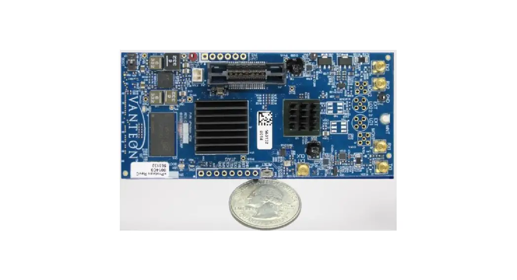
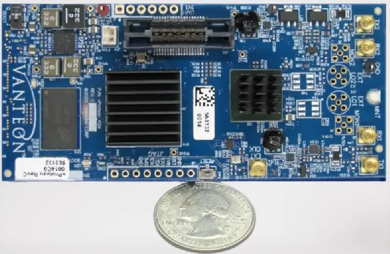
The Vanteon vProtean™ is a 2×2 software defined radio (SDR) that targets communications, signal intelligence, and other multi-band processing applications. It is based on the Analog Devices ADRV9004 highly integrated wideband RF transceiver and the Xilinx Zynq-7020 all programmable System-on-Chip (SoC). The vProtean SDR has a custom RF front end that is highly flexible, allowing its frequency range to be configured from 30 to 6000 MHz.
Each vProtean SDR is pre-loaded with the vProtean SDR Evaluation Kit (VPROKIT-21) firmware. The VPROKIT-21 firmware includes Vanteon proprietary, programmable logic cores and executable code to perform transmit and receive functions via a menu-based UI over USB enabled com port from a host computer (host not included). An encrypted Vivado Project of the VPROKIT-21’s FPGA firmware, along with source code of the User Interface (UI) firmware is available under a free license agreement. The vProtean schematic and layout design files, and Vanteon-proprietary DSP cores are available with a paid license. Contact Vanteon Sales for more information.
![]() The vProtean SDR evaluation kit is sold for evaluation purposes. If you choose to use your vProtean SDR evaluation kit to transmit using an antenna, it is the user’s responsibility to make sure that they are in compliance with all local laws and regulations.
The vProtean SDR evaluation kit is sold for evaluation purposes. If you choose to use your vProtean SDR evaluation kit to transmit using an antenna, it is the user’s responsibility to make sure that they are in compliance with all local laws and regulations.
Proper Care and Handling
All Vanteon products are thoroughly tested before shipment. The vProtean SDR is guaranteed to be functional at the time it is received by the customer. Improper use or handling of the vProtean SDR can easily cause the device to become nonfunctional. Listed below are some examples of actions which can prevent damage to the unit:
- Never allow metal objects to touch the circuit board while powered.
- Always properly terminate the transmit port with an antenna or 50Ω load.
- Always handle the board with proper anti-static methods.
- Never allow the board to directly or indirectly come into contact with any voltage spikes.
- Never allow any water, or condensing moisture, to come into contact with the boards.
- Never apply more than 0 dBm of power into any RF input.
- Always use at least 30dB attenuation if operating in a loopback configuration.
![]() The vProtean SDR evaluation kit is supplied with heatsinks of the FPGA and transceiver IC. Under heavy processing and/or high output power levels additional airflow may be required to ensure the components remain in the specified operating temperature range to prevent damage.
The vProtean SDR evaluation kit is supplied with heatsinks of the FPGA and transceiver IC. Under heavy processing and/or high output power levels additional airflow may be required to ensure the components remain in the specified operating temperature range to prevent damage.
Evaluation Kit Contents
The vProtean SDR Evaluation Kit (VPROKIT-21-C) contains the following items:
- vProtean Software-Defined Radio
- vProtean Carrier (vCarrier) with mounting hardware
- 120VAC power supply
- USB cable (Type A to Type C)
- 16GB microSD card with SD card adapter
Technical Overview
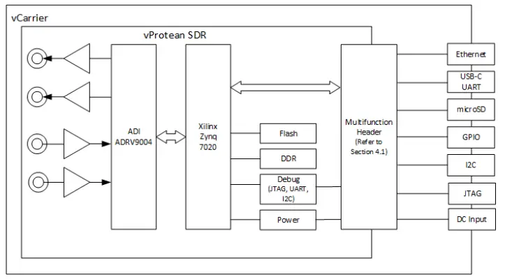
4.1 Block Diagram
4.2 vProtean Evaluation Kit Specifications
| Frequency Band 1 | 30 to 6000 MHz |
| Instantaneous Bandwidth | 12 kHz to 40 MHz |
| Number of transmitters | 2 |
| Number of receivers | 2 |
| Maximum Transmit Power | +19 dBm |
| Maximum Input Receive Power | 0 dBm |
| Antenna connections | 50Ω MMCX RF connectors |
| Power control | Wide range of output power from –20 dBm to +19 dBm |
| Flash | 512 Mb |
| DDR SDRAM | 4 Gb |
| vCarrier Input Voltage | 6-30 VDC |
vProtean Interfaces
5.1 vProtean Connectors
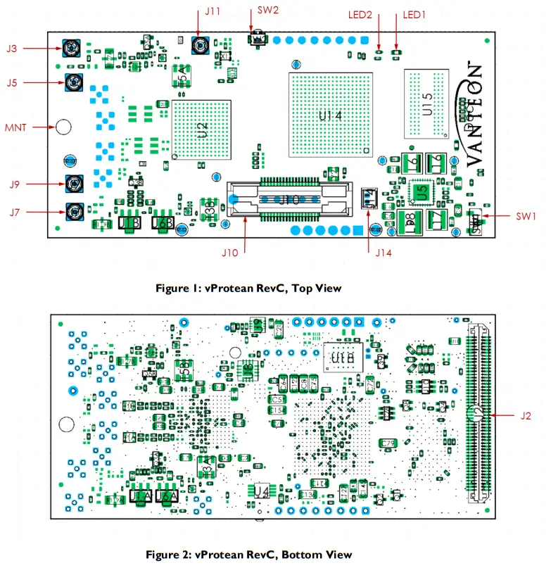
The vProtean SDR has a number of connectors that allow it to be interfaced to the vCarrier board, as well as connectors for external antennas. The table below lists all of the connectors and their associated functions. Refer to Figure 1 and Figure 2 for connector locations.
| Connector | Type | Function |
| J2 | 2×50 100 pin header | JTAG, UART, Boot Mode, Power, Reset, USB, Ethernet, SD Card, I2C, GPIO Contact Vanteon for additional information |
| J3 | MMCX | Transmit 1 |
| J5 | MMCX | Receive 1 |
| J7 | MMCX | Transmit 2 |
| J9 | MMCX | Receive 2 |
| J10 | MICTOR | Debug |
| J11 | MMCX | External Clock |
| J14 | 2-pin PicoBlade header | Fan Connector |
5.1.1 J14 Connector
The J14 connector is a fan connector that can be used to provide cooling for the evaluation kit. It can deliver 5V up to 200mA. Connect a suitable fan using a Molex PicoBlade connector (for example, Molex part number 15134-0200).
| Pin | Description |
| 1 | FAN – |
| 2 | FAN + |
5.2 Switches
The vProtean SDR has two switches, whose function is described in the table below.
| SW1 | Switch | Boot Mode. Move to position J (towards Vanteon logo) for JTAG boot mode, position Q for QSPI or SD card booting. Can be overridden by carrier jumpers. |
| SW2 | Pushbutton | Reset. Can also be driven from carrier board. |
5.3 LEDs
The vProtean SDR has two LEDs, whose function is described in the table below.
| LED1 | Blue | On when Zynq 7020 programmable logic has been programmed |
| LED2 | Green | Software control |
5.4 Mounts
The vProtean SDR has one mounting point. In the standard configuration, it is designed for a standoff height from a carrier PCB of 9.5mm (3/8”).
| MNT | Standoff | Use threaded spacer, screws and locking washer (supplied in kit). The smaller head screw is intended for the top side, to avoid collision with RF connectors |
vCarrier Interfaces
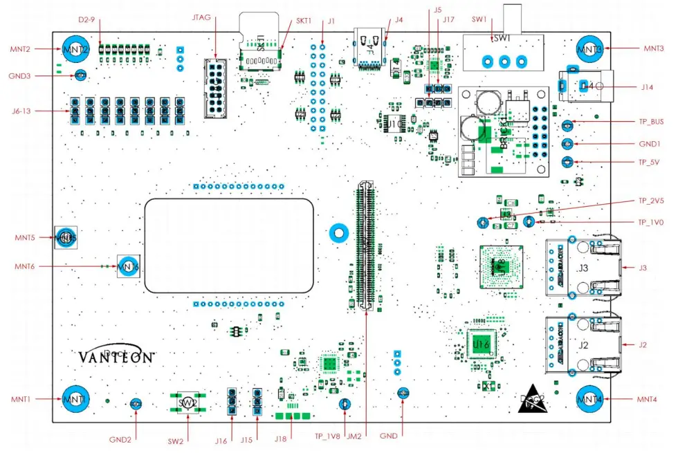 6.1 vCarrier Connectors (Revision D)
| Connector | Type | Function |
| JM2 | 100 pin header | JTAG, UART, Boot Mode, Power, Reset, USB, Ethernet, SD Card, I2C, GPIO Contact Vanteon for additional information |
| J1 | Header | User Defined Differential IO (optional, if fitted) |
| J2 | RJ45 | Ethernet 1 interface (Not supported) |
| J3 | RJ45 | Ethernet 0 interface |
| J4 | USB-C | USB – UART serial interface |
| J5 | Header | I2C 3.3V interface |
| J6-13 | Header | 2.5V GPIO. Jumpers may be used to set input levels, or removed to use center pins as outputs. Contact Vanteon for additional information |
| J14 | DC Jack | 2.5mm DC barrel jack for system power input. 6-30VDC, 20W |
| J15-16 | Header | Boot mode jumper select. May be used to override vProtean boot mode switch, otherwise leave off. Contact Vanteon for additional information |
| J17 | Header | USB power enable. Unused with DC supply. |
| J18 | USB-Micro | USB-OTG host/device interface (Not supported) |
| SKT1 | microSD | microSD card connector for storage of system firmware and TX/RX data. |
6.2 Test Points
The vCarrier has 9 test points for measuring system voltages, whose function is described in the table below.
| GND0-3 | Test Hook | System ground |
| TP_1V0 | Test Hook | Carrier 1.0V |
| TP_1V8 | Test Hook | Carrier 1.8V |
| TP_2V5 | Test Hook | Carrier 2.5V |
| TP_5V | Test Hook | Carrier 5.0V |
| TP_BUS | Test Hook | System input supply voltage |
6.3 Switches
The vCarrier has two switches, whose function is described in the table below.
| SW1 | Slider | System power switch. Slide right to enable power from DC jack. |
| SW2 | Pushbutton | System Reset |
6.4 LEDs
The vCarrier has eight LEDs, whose function is described in the table below.
| D2-9 | Green | Displays the status of GPIO0-7 |
6.5 Mounts
The vProtean SDR has mounting points for the system and for the vProtean SDR. In the standard configuration, it is designed for a standoff height from a carrier PCB of 9.5mm (3/8”).
| MNT1-4 | Foot | vCarrier mounting points. Fitted with rubber feet as default |
| MNT5 | Standoff | Use threaded spacer, screws and locking washer (supplied in kit). The smaller head screw is intended for the top side, to avoid collision with RF connectors |
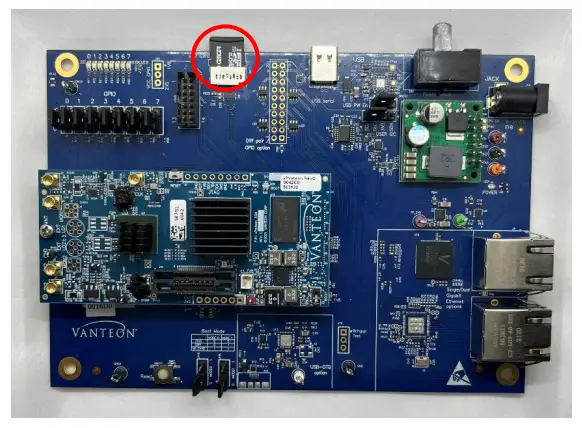
Evaluation Kit Assembly
Follow the step by step instructions below to assemble your vProtean SDR evaluation kit.![]() Please refer to Section 2 for proper care and handling
Please refer to Section 2 for proper care and handling![]() For more information view our setup video here, or visit our website at https://vanteon.com/vprotean/
For more information view our setup video here, or visit our website at https://vanteon.com/vprotean/
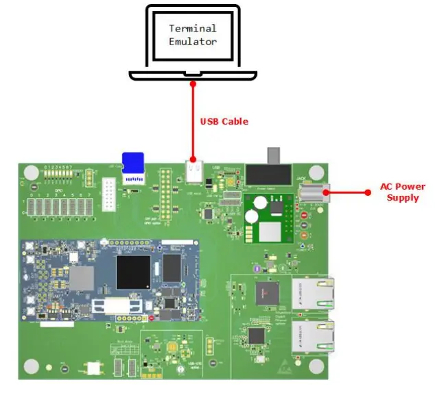
- Install the provided microSD card into the microSD socket (SKT1) on the vCarrier.

- Connect the vCarrier USB-C port (J4) to a customer provided PC using the provided cable.
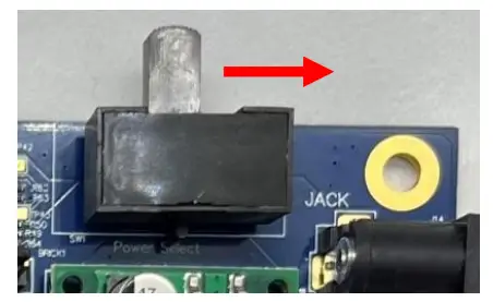
- Connect the supplied AC power supply to the DC Jack (J14) on the vCarrier.
- Connect the AC power supply to an AC outlet.
- Turn on the vProtean SDR evaluation kit by sliding the switch (SW1) on the vCarrier towards the DC Jack (J14).

User Console
The vProtean SDR evaluation kit is preloaded with a menu-based application that allows a user to perform transmit and receive functions through the USB interface. This section explains how to use the vProtean SDR evaluation application. The examples in this section refer to software version 3.4. Older versions may not support some of the features listed. To access the preloaded evaluation application connect the vProtean SDR evaluation kit USB port to a PC using the appropriate USB cable. Use a terminal emulator program (for example, PuTTY or HyperTerminal) on the PC to open a terminal session using the virtual COM port associated with the vProtean SDR evaluation kit.
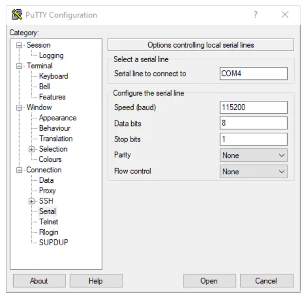
To determine the appropriate virtual COM port, open Device Manager and find the associated USB Serial Port. In the example below COM4 should be used.
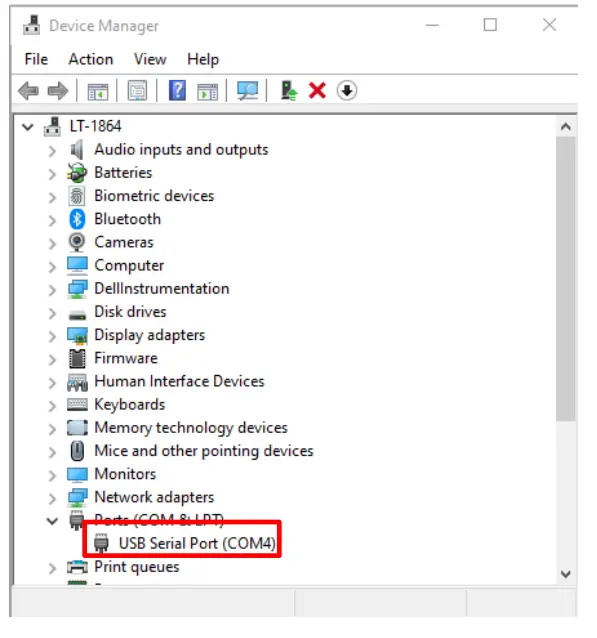
Configure the virtual serial port in the terminal emulator as 115200 baud-8-N-1. See example below.
Vanteon Proprietary – Information subject to change without notice
![]() The evaluation kit application does not provide access to the full capabilities of the vProtean SDR platform.
The evaluation kit application does not provide access to the full capabilities of the vProtean SDR platform.
To explore additional options and functionality call us at 888.506.5677 or email us at [email protected].
8.1 Main Menu
The vProtean SDR evaluation application has a hierarchical menu structure that allows you to configure the radio and to transmit and receive test waveforms. The main menu consists of the following status and commands:
| Item | Name | Function |
| – | TX RX Sample Rate | Display of the pre-configured sample rate (not user configurable) |
| – | FPGA Temperature | Display of the FPGA temperature |
| – | ADRV Temperature | Display of the ADRV IC temperature |
| – | RX1 RSSI | Display of RX1 receive signal strength indicator (RSSI) in dB relative to full scale |
| – | RX2 RSSI | Display of RX2 receive signal strength indicator (RSSI) in dB relative to full scale |
| – | TX1 | State of the transmit (Primed/Enabled) |
| – | TX2 | State of the transmit (Primed/Enabled) |
| 1 | TX1 RX1 Settings | Configure TX1 and RX1 |
| 2 | TX2 RX2 Settings | Configure TX2 and RX2 |
| 3 | Capture RX | Initiate RX capture according to RX capture settings |
| 4 | RX Waveform Capture Settings | Configure the RX capture parameters |
| 5 | Recalibrate System | Force a transceiver recalibration |
| Item | Name | Function |
| C | Switch to CLI | Switch to the command line interface |
![]() Please contact Vanteon for more information on the command line interface.
Please contact Vanteon for more information on the command line interface.
Type menu in the CLI to return to the menu-based application.
8.1.1 TX1/RX1 and TX2/RX2 Settings Menu
There are two submenus for configuring the TX1/RX1 and TX2/RX2 pairs. This section covers both submenus and refers to TX1 and TX2 as a generic TX_, and RX1 and RX2 as a generic RX_.
| Item | Name | Function |
| 1 | TX_/RX_ Frequency | Set the TX_/RX_ frequency (30 MHz to 6000 MHz) |
| 2 | Toggle TX_ | Toggles transmit for TX_ on/off PRIMED – Transmit disabled ENABLED – Transmit enabled |
| 3 | TX_ Waveform Select | Go to TX_ waveform select menu |
| 4 | Digital Attenuation (dB) | Attenuation that is applied digitally to the transmit waveform (0 to 100 dB) |
| 5 | TX_ Front End Atten (dB) | Sets the attenuation in the ADRV9004 (0 to 41.5 dB), value can only be changed when TX is disabled |
| 6 | TX_ BOOST | Adds an additional 3 dB to the transmit |
| 7 | Toggle RX_ | Toggles receive for RX_ on/off PRIMED – Receive disabled ENABLED – Receive enabled |
![]() The vProtean SDR evaluation kit is supplied with heatsinks on the FPGA and transceiver IC. Under heavy processing and/or high output power levels additional airflow may be required to ensure the components remain in the specified operating temperature range to prevent damage.
The vProtean SDR evaluation kit is supplied with heatsinks on the FPGA and transceiver IC. Under heavy processing and/or high output power levels additional airflow may be required to ensure the components remain in the specified operating temperature range to prevent damage.
The FPGA and ADRV temperatures displayed on the main menu should be monitored by the user, and external cooling (for example, directed fan) should be applied as needed to prevent damage.
The TX Waveform Select Menu configures the waveform that is transmitted when the TX is toggled on. When the transmit is enabled, the selected waveform is transmitted repeatedly.
| Item | Name | Function |
| – | Current Waveform | Display the current selected waveform |
| 1 | Zeros | Fills transmit buffer with zero waveform |
| 2 | CW | Single tone at carrier frequency |
| 3 | USB Tone, Offset=FS/32 | Upper side band waveform, FS=sample rate |
| 4 | Dual Tone, Offset=FS/32+FS/8 | Dual tone waveform, FS=sample rate |
| 5 | File | Go to file select menu to load waveform file from SD card |
| Item | Name | Function |
| 6 | Ramp | Transmits a waveform whose amplitude increases overtime |
| 7 | Chirp | Transmits a linear FM signal |
8.1.2 TX1 and TX2 File Select Menu
The File Menu allows the user to select a user defined file from the SD card that specifies the transmit waveform. Use the UP and DOWN arrows on your keyboard to highlight the file you want to select and press Enter.
The format of the filename must have a “.iq” extension to show up in the file list.
The format of a transmit waveform is a .CSV file with one sample (IQ pair) per line with I and Q values separated by a comma. Channel 1 and Channel 2 data is alternated in the file, where the first line is TX1. Values must be within the range of -32768 to 32767, inclusive. See below for an example file format.
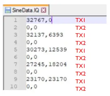
The TX waveform file must contain between a minimum of 512 samples and a maximum of 4,194,304 samples, inclusive. The number of samples should be a multiple of 512. If the number of samples is not a multiple of 512, the TX waveform will be zero padded to the next multiple of 512.![]() The evaluation kit should be powered down whenever mounting or removing the microSD card.
The evaluation kit should be powered down whenever mounting or removing the microSD card.
8.1.3 RX Waveform Capture Settings Menu
The RX Waveform Capture Settings Menu allows the user to set the number of samples captured and the file to which the samples are saved. It also allows the user to configure which RX channel will be captured.
The format of a captured waveform is a .CSV file with one sample (IQ pair) per line with I and Q values separated by a comma. Channel 1 and Channel 2 data is alternated in the file. See below for an example.![]() Due to a known bug in version 3.4 the first RX2 sample should be discarded prior to post processing
Due to a known bug in version 3.4 the first RX2 sample should be discarded prior to post processing
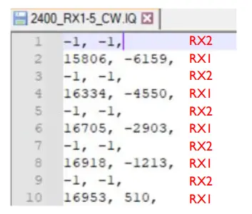
If the captured waveform filename has an “.iq” extension it will show up in the TX waveform list if the capture was successful.
| Item | Name | Function |
| 1 | Filename | The name of the file to save the RX samples to. The filename can be up to 9 characters. The filename extension can be up to 2 characters. It is recommended that the filename extension be “.iq” |
| 2 | Samples | The number of samples to capture. Must be a multiple of 512 IQ samples. |
| 3 | RX Channel [1,2,3] | Configure which RX channel the capture should be performed on. 1 – Capture RX1 2 – Capture RX2 3 – Capture RX1 & RX2 |
Customer Support
If you experience difficulty after reading the manual and/or using the product, please feel free to contact [email protected] for additional assistance.
Need support?
Vanteon offers contract engineering services and can assist you in implementing the vProtean SDR into your system.
Need short term support?
Purchase a 2, 4, 8, or 40-hour block of engineering support to get access to a team of engineers to support your needs. Engineering support blocks can be purchased directly
from our website with any major credit card. For more information visit our website at https://vanteon.com/engineering-support-blocks/.
Terms and Conditions of Sale
10.1 General Product Terms
All sales of product are subject to the terms and conditions described in “Vanteon Corporation – Terms and Conditions of Product Sales”. Unless explicitly agreed to in writing, Vanteon rejects all modifications to these standard terms and conditions.
10.2 One Year Warranty
Vanteon Corporation provides a One-Year Limited Warranty for all products sold. Should this product, in Vanteon Corporation’s opinion, fail to be in good working order during the warranty period, Vanteon Corporation will, at its option, repair or replace this product at no charge, provided that the product has not been subject to abuse, misuse, accident or unauthorized modification or repair.
Products returned to Vanteon must be pre-authorized by Vanteon and sent prepaid, insured, and packaged for safe shipment. Vanteon will return this product by prepaid ground shipment service. Should the product prove to be irreparable, Vanteon reserves the right to substitute an equivalent product if available. Full warranty details are included in “Vanteon Corporation – Terms and Conditions of Product Sales” available at www.vanteon.com.
The above warranty is the only warranty authorized by Vanteon for this product. Under no circumstances will Vanteon be liable in any way for any damages, including any lost profits, business revenue, special, indirect, incidental, exemplary, punitive, or consequential damages arising out of the use of, or inability to use such product.
Copyright Notice
The information contained in this document is subject to change without notice. Vanteon Corporation shall not be liable for errors contained herein or for incidental or consequential damages in connection with the furnishing, performance, or use of this material. This document contains proprietary information that is protected by copyright. All rights are reserved. No part of this document may be photocopied, reproduced, or translated to another language without the prior written consent of Vanteon Corporation. Copyright © 2022 by Vanteon Corporation.
Trademark Acknowledgement
Vanteon Corporation acknowledges all trademarks, registered trademarks and/or copyrights referred to in this document as the property of their respective owners. Not listing all possible trademarks or copyright acknowledgements does not constitute a lack of acknowledgement to the rightful owners of the trademarks and copyrights mentioned in this document.
Vanteon Corp. | 888.506.5677 | 585.419.9555 | 99 Garnsey Road, Suite 200 | Pittsford, NY 14534 | www.vanteon.com
![]()


