![]()
14545 Controller For Compressor and Condenser Station
User Guide
AKO-14545
AKO-14545-C
Warnings
-If the equipment is used without adhering to the manufacturer’s instructions the device safety requirements could be compromised. -The installation location of the equipment must be protected from vibrations, water, and corrosive gases where the ambient temperature does not exceed the value featured in the technical data.
-To ensure a correct reading the probe must be located away from external effects.
-The power circuit should be equipped with a switch for its disconnection of at least 2 A, 230 V, situated near the appliance. The cables will be fed in from the rear and will be typed H05VV-F or H05V-K.
-The section to be used will depend on the local standard in force, however, must never be less than 1 mm.
-The wiring cables for the contact relays must have a section of 2.5 mm.
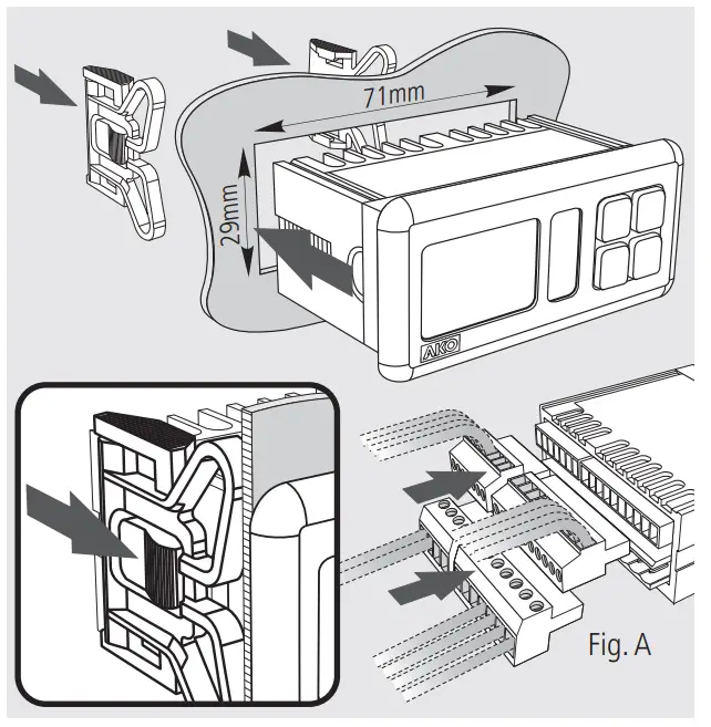
-Make the connection before plugging in the terminals to the equipment (See Fig. A).
ATTENTION: The equipment is not compatible with AKO-14917 (external communication module) and AKO-14918 (programming key).
Installation Quick start
 Quick start
By using keys ![]() and
and ![]() select the most suitable option according to the installation type in accordance with the table in the “WIZARD” appendix and press SET. The wizard configures the equipment parameters and assigns the input and output functions according to the installation type chosen.
select the most suitable option according to the installation type in accordance with the table in the “WIZARD” appendix and press SET. The wizard configures the equipment parameters and assigns the input and output functions according to the installation type chosen.
Select the refrigerant gas type used from amongst the following options:
0=R134a 1=R404a 2=R717a 3=R22 4=R410a 5=R507a 6=R744 7=R407a 8=R407f 9=R1234y
10=R448a 11=R449a 12=R450a 13=R454A 14=R454C 15=R455A 16=R1234ze 17=R515b 18=R452A 19=R452b
Select the primary and secondary display units from amongst the following options:
0=bar-ºC; 1=psi-ºF; 2=psi-ºC; 3=bar-ºF; 4=ºC-bar; 5=ºF-psi; 6=ºC-psi; 7=ºF-bar
Configure the rest of the parameters to their default value? :
0=No, the configuration is kept for all the parameters except for C01, C02, C04, C05 C06, C08, and C09.
1=Yes, all the parameters are configured to their default value (see parameters table)
(This option does not affect parameters C01, C02, C04, C05 C06, C08, and C09)
“WIZARD” table
The “WIZARD” table in the appendix is divided into 3 groups of columns. The first describes the different installation types (number of compressors and fans, if they have an inverter, etc.) associated with the INI option.
The second group specifies the function assigned to each relay depending on the INI option selected.
The third group specifies the function assigned to each digital input depending on the INI option selected.
Installation type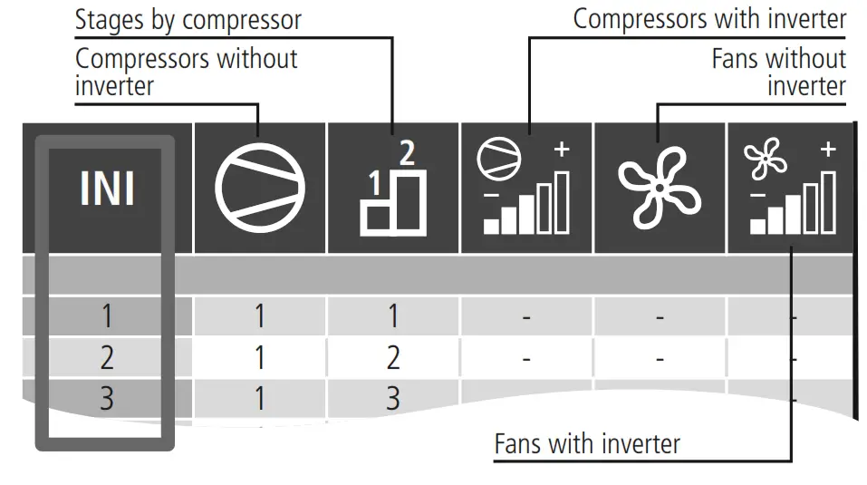
Relay function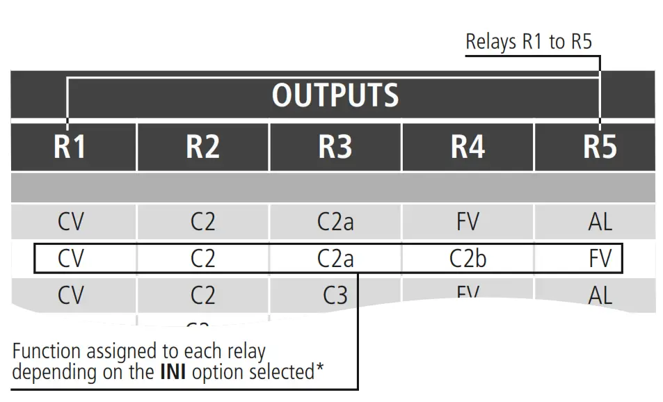
Input function
*The meaning of each function is described in the “WIZARD” appendix
Operation
ESC key
In the programming menu, exit the parameter without saving changes, return to the previous level, or exit programming.
SET key
By pressing this key for 1 second the probe display units change (according to parameter C09).
Pressing it for 10 seconds accesses the programming menu.
In the programming menu, it accesses the level shown on the display or, during the setting of a parameter accepts the new value.![]() UP key
UP key
By pressing this key for 1-second probe 2 is displayed for 5 seconds (or probe 1, according to parameter P02). By pressing a second time the probe ambient temperature value will be shown (only if I07 or I08=3).
In the programming menu, it allows scrolling around the different levels, or during the setting of a parameter, changing its value.![]() DOWN key
DOWN key
Pressing this key returns the equipment to its normal operation after an alarm that requires a reset (the causes which triggered the alarm must have disappeared).
In the programming menu, it allows scrolling around the different levels, or during the setting of a parameter, changing its value.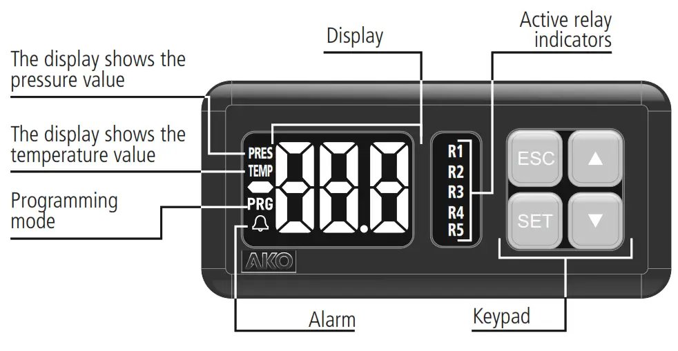
Operation start-up
Upon being supplied with power the equipment will start up in WIZARD mode (INI / 1 flashing), press ![]() or
or ![]() to select the most suitable option for the installation type, and check the options in the “WIZARD” appendix.
to select the most suitable option for the installation type, and check the options in the “WIZARD” appendix.
The wizard configures the equipment parameters and assigns the input and output functions according to the installation type chosen.
Technical specifications
Power supply . . . . . . . . . . . . . . . . . . . 90-240 V~ 50/60 Hz
Maximum voltage in the SELV circuits . . . . . . . . . . . . . . 20 V
Inputs . . . . . . . . . . . . . . . . 2 analog inputs + 6 digital inputs
Relays R1 to R4 . . . . . . . . (EN60730-1: 5(4) A 250 V~ SPST)
Relay R5 . . . . . . . . . . . . . (EN60730-1: 5(4) A 250 V~ SPDT)
No. of relay operations . . . . . . . . . . EN60730-1: 100.000 operations
Types of probes . . . . . . . . . . . . . . . . . . . . NTC AKO-149xx
. . . . . . . . . . . . . . . . . . . . . . . . . . . . . . . . . . . . . . 4-20 mA
. . . . . . . . . . . . . . . . . . . . . . . . . . . . . . . . 0-5 V ratiometric
Measuring range
NTC . . . . . . . . . -50,0 ºC to +99,9 ºC (-58,0 ºF to 211 ºF)
4-20 mA / 0-5 V . . . . . . . . . . . . . . . . . . . . . . -60 to 999
Resolution
NTC . . . . . . . . . . . . . . . . . . . . . . . . . . . 0.1 ºC (0.1 ºF)
4-20 mA / 0-5 V -99.9 to 99.9. . . . . . . . . . . . . . . 0.1
≤-100 / ³ 100 . . . . . . . . . . . . . . 1
Working environment . . . . . . . -10 to 50 ºC, moisture <90 %
Storage environment . . . . . . . . -30 to 70 ºC, moisture <90 %
Protection degree of the front part . . . . . . . . . . . . . . . . IP65
Fixing . . . . . . . . . . . . . . . . . . . Panel mounting with anchors
Panel cavity dimensions . . . . . . . . . . . . . . . . . . . 71 x 29 mm
Front part dimensions . . . . . . . . . . . . . . . . . . . . 79 x 38 mm
Depth . . . . . . . . . . . . . . . . . . . . . . . . . . . . . . . . . . . 61 mm
Connections:
Terminal to screw for cables with a section of up to 2.5 mm Control device classification: Built-in assembly, with Type 1.B automatic operation action feature, for use in clean situations, logical support (Software) class A and continuous operation. Degree of contamination 2 acc. to UNE-EN 60730-1. Double power input insulation, secondary circuit, and relay output.
Rated pulse voltage . . . . . . . . . . . . . . . . . . . . . . . . . 2500 V
Pressure ball test temperature:
Accessible parts . . . . . . . . . . . . . . . . . . . . . . . . . . 75 ºC
Parts that position active elements . . . . . . . . . . . . 125 ºC
Voltage and current declared by the EMC tests: . . . . . . . . . . 207 V, 17 mA
Radio interference suppression test current . . . . . . . . . 270 mA
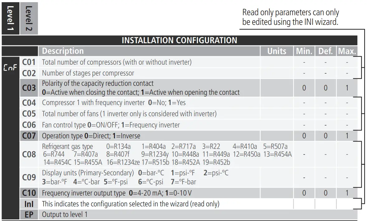
Table of parameters and messages
The Def. column indicates the ex-works configured default parameters. The pressure values featured on the table are expressed in bar and those for temperature in ºC. If the wizard meanwhile selects another set of units (parameter C09), the equipment will make the conversion automatically.
INSTALLATION CONFIGURATION
EVAPORATION CONFIGURATION 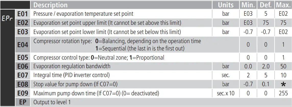
CONDENSATION CONFIGURATION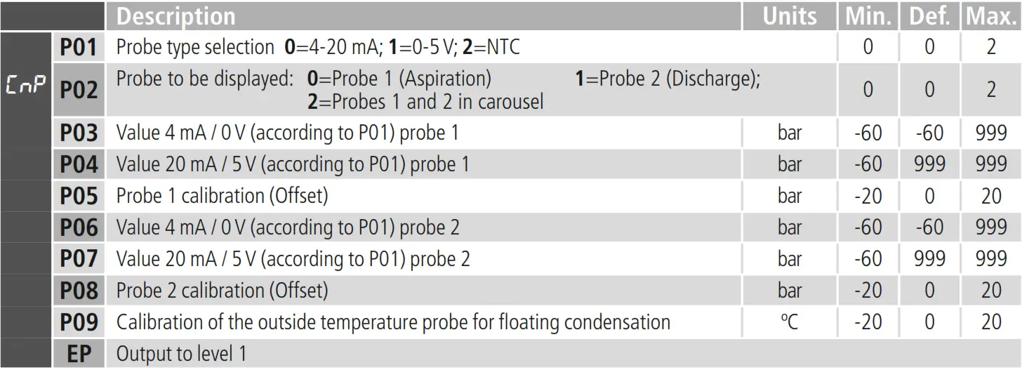
CONDENSATION CONFIGURATION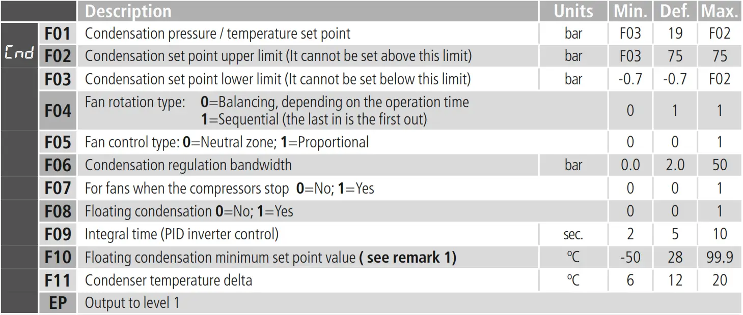
PROBE CONFIGURATION Units
DIGITAL INPUT CONFIGURATION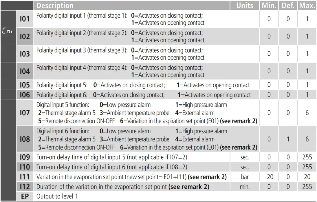
ENERGY-SAVING CONFIGURATION
| Description Start of energy-saving – Day of the week: =Deactivated 1=Monday 2=Tuesday | Units | Min. | Def. | Max. | |||
| ES | S01 | 3=Wednesday 4=Thursday 5=Friday 6=Saturday 9=Monday to Saturday 10=Monday to Friday | 7=Sunday 8=Monday 11=Saturday to Sunday | to Sunday | 0 | 0 | 11 |
| S02 | Start of the energy-saving – Hour (see remark 2) | h. | 0 | 0 | 23 | ||
| S03 | Start of the energy-saving – Minute (see remark 2) | min. | 0 | 0 | 59 | ||
| S04 | Duration of the energy-saving (see remark 2) | h. | 0 | 0 | 24 | ||
TIMING CONFIGURATION
| Description | Units | Min. | Def. | Max. | ||
| t01 | Minimum operation time for a compressor | sec. x10 | 1 | 2 | 999 | |
| t02 | Minimum disconnection time for a compressor ** | sec. x10 | 1 | 2 | 999 | |
| t03 | Delay time between the compressor start-up/stage and the next one | sec. | 1 | 30 | 999 | |
| t04 | Delay time between the compressor stop/stage and the next one | sec. | 1 | 10 | 999 | |
| t05 | Minimum operation time for a fan | sec. x10 | 1 | 1 | 999 | |
| t06 | Minimum disconnection time for a fan | sec. x10 | 1 | 1 | 999 | |
| t07 | Delay time between the fan start-up and the next one | sec. | 1 | 2 | 999 | |
| t08 | Delay time between the fan stop and the next one | sec. | 1 | 2 | 999 | |
| EP | Output to level 1 | |||||
CONFIGURATION OF PROTECTIONS AND ALARMS
| Description | Units | Min. | Def. | Max. | |||
|
| A01 | Number of active compressor stages with error in probe 1 | 0 | 0 | |||
| A02 | Number of active fans or inverter % with error in probe 2 | Without inverter | 0 | C05 | C05 | ||
| With inverter | 0 | 100% | 100% | ||||
| A03 | Low-pressure alarm in probe 1 | bar | -0.7 | 0 | 75 | ||
| A04 | Low-pressure alarm differential | bar | 0.1 | 1.0 | 20 | ||
| A05 | High-pressure alarm in probe 2 | bar | -0.7 | 20 | 75 | ||
| A06 | High-pressure alarm differential | bar | 0.1 | 1.0 | 20 | ||
| A07 | Alarm delay after reaching the value | sec. | 0 | 60 | 999 | ||
| A08 | Delay of temperature alarms in the start-up. | sec. | 0 | 0 | 255 | ||
| A09 | High-pressure alarm limit (per digital input) per hour without a manual reset. (If I07 or I08=1) (0=deactivated) Once the limit has been exceeded a manual reset will be required for each new alarm. | 0 | 0 | 255 | |||
DATE AND TIME CONFIGURATION
| Description | Units | Min. | Def. | Max. | ||
| r01 | Hour | 00 | 00 | 23 | ||
| r02 | Minutes | 00 | 00 | 59 | ||
| r03 | Day | 1 | 1 | 31 | ||
| r04 | Month | 1 | 1 | 12 | ||
| r05 | Year | 00 | 15 | 99 | ||
ACCESS AND INFORMATION CONTROL
| Description | Units | Min. | Def. | Max. | ||
| P5 | Address for units with communication | 1 | 1 | 255 | ||
| L5 | Access code (Password) | 0 | 0 | 999 | ||
| PU | Program version | – | – | – | ||
| Pr | Check | – | – | – | ||
OPERATION TIMES
| Description | Units | Min. | Def. | Max. | ||
|
| c1 | This shows the operation time for the compressor or fan 1 | hours x10 | – | – | 999 |
| c2 | This shows the operation time for the compressor or fan 2 | hours x10 | – | – | 999 | |
| c3 | This shows the operation time for the compressor or fan 3 | hours x10 | – | – | 999 | |
| c4 | This shows the operation time for the compressor or fan 4 | hours x10 | – | – | 999 | |
| c5 | This shows the operation time for the compressor or fan 5 | hours x10 | – | – | 999 | |
| EP | Output to level 1 | |||||
Programming output
* Depending on the compressor control type: Proportional=E01; Neutral zone=E01-E06. ** If the compressor is equipped with an inverter, this period of time halves. *** The number of stages depends on the configuration selected in the wizard. Remark 1: The equivalent value in pressure is calculated depending on the refrigerant gas
specified in the wizard. Remark 2: In the event of the energy-saving and the variation in the set point per digital input being activated at the same time, the variation in the set point per digital input will always prevail.
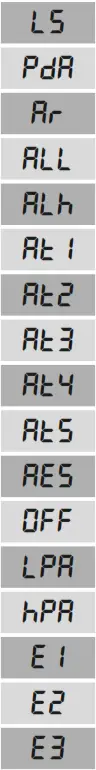 | Access code (Password) request | D | – |
| Pump down detained due to time | D | – | |
| Clock battery dead or clock deprogrammed | D | – | |
| Low-pressure alarm due to probe 1 | D | R | |
| High-pressure alarm due to probe 2 | D | R | |
| Thermal alarm 1 | D | R | |
| Thermal alarm 2 | D | R | |
| Thermal alarm 3 | D | R | |
| Thermal alarm 4 | D | R | |
| Thermal alarm 5 | D | R | |
| Severe external alarm (input I5 or I6) | D | R | |
| Remote regulation detained due to digital input (input I5 or I6) | D | – | |
| Low-pressure alarm due to digital input (input I5 or I6) | D | R | |
| High-pressure alarm due to digital input (input I5 or I6) | D | R | |
| Error in probe 1 (open circuit, probe crossed or out of range) | D | R | |
| Error in probe 2 (open circuit, probe crossed or out of range) | D | R | |
| Error in probe 3 (open circuit, probe crossed or out of range) | D | R |
D: The message is shown on the display.
R: Alarm relay activated (if available, see WIZARD table).


