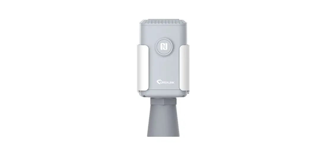
![]() EM500-UDL Ultrasonic Distance Level Sensor
EM500-UDL Ultrasonic Distance Level Sensor
User Guide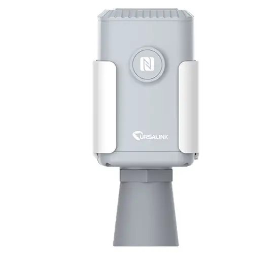
Safety Precautions
Ursalink will not shoulder responsibility for any loss or damage resulting from not following the instructions of this operating guide.
- The device must not be disassembled or remodeled in any way.
- Please clarify your application environment before deployment so that the device can function well.
- The device is not intended to be used as a reference sensor, and Ursalink will not should responsible for any damage which may result from inaccurate readings.
- Do not place the device in places that are already out of measuring range or where the temperature is below/above the operating range.
- Make sure electronic components do not drop out of the enclosure while opening.
- When closing the lid, make sure the lid is fitted the right way, so that the enclosure is properly sealed.
- When installing the battery, please install it accurately, not reversely or with the wrong model.
- The device must never be subjected to shocks or impacts.
Declaration of Conformity
Ursalink EM500-UDL is in conformity with the essential requirements and other relevant provisions of the CE, FCC, and RoHS.
EM500-UDL is short for EM500-UDL-915.
© 2017-2020 Xiamen Ursalink Technology Co., Ltd.
All rights reserved.
All information in this guide is protected by copyright law. Whereby, no organization or individual shall copy or reproduce the whole or part of this user guide by any means without written authorization from Xiamen Ursalink Technology Co., Ltd.
 For assistance, please contact
Ursalink technical support:
Email: [email protected]
Tel: 86-592-5023060
Fax: 86-592-5023065
Revision History
| Date | Doc Version | Description |
| April 7, 2020 | V 1.0 | Initial version |
Overview
Description
EM500-UDL is an outdoor environment monitoring sensor mainly used to measure distance without object interface contact. EM500-UDL device is battery-powered and designed for multiple mounting ways. It is equipped with NFC (Near Field Communication) and can easily be configured from a smartphone or a PC software.
Sensor data are transmitted in real-time using the standard LoRaWAN protocol. LoRaWAN enables encrypted radio transmissions over long distances while consuming very little power.
The user can obtain sensor data and view the trend of data change through Ursalink Cloud or the ough the user’s own Network Server.
Features
- Distance detection without immediate contact
- Easy configuration via NFC
- Standard LoRaWAN support
- Ursalink Cloud compliant
- Low power consumption with 19000mAh replaceable battery
Specifications
| LoRaWAN | |
| Sensitivity | -147dBm@300bps |
| Mode | OTAA/ABP Class A |
| Antenna | Embedded Ceramic Antenna |
| Distance Measurement | |
| Range | EM500-UDL-W050:0.3-5m EM500-UDL-W100:0.5-10m (Customize for snow level detection) |
| Resolution | 1 mm |
| Accuracy | ± 1% |
| Physical Characteristics | |
| Power Supply | 19000 mAh Li-SoCl2 battery |
| Battery Life | 6 year (10 min interval, SF12) >10 years (10 min interval, SF7) |
| Operating Temperature | -20°C to +70°C |
| Relative Humidity | 0% to 100% (non-condensing) |
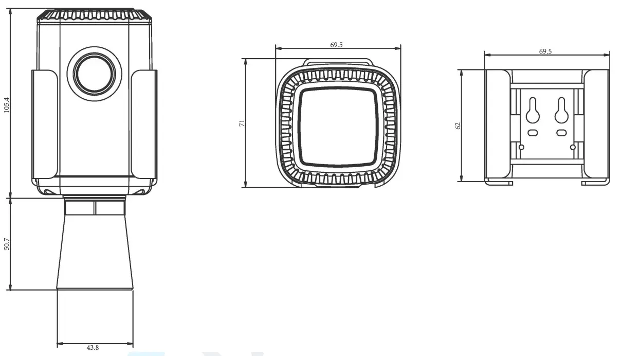
| Dimension | 156.1 × 71 × 69.5 mm |
| Mounting | Pole, wall, DIN rail |
Dimensions(mm)
Hardware Introduction
Packing List
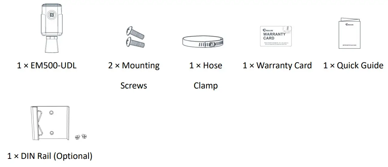
![]() If any of the above items are missing or damaged, please contact your Ursalink sales representative.
If any of the above items are missing or damaged, please contact your Ursalink sales representative.
Product Overview
Front View:
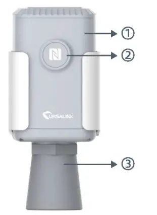
①LoRa Antenna (Internal)
②NFC Area
③Ultrasonic Horn
Front View:
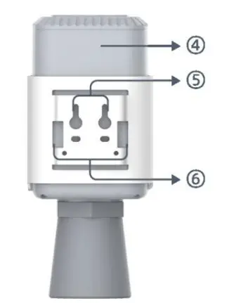
Back View:
④Battery (Internal)
⑤Wall Mounting Holes
⑥Pole Mounting Holes
Sensor Installation
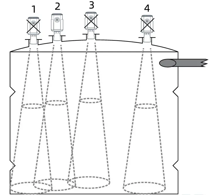
Installation Location
When installing EM500-UDL, please take in mind:
- Ensure the location of EM500-UDL is within the communication range of the LoRaWAN gateway.
- Device must sit in a vertical position on top of the object and be fitted such that it has a clear path to the object.
- Place the device where it is not close to the sidewall and without internal obstructions that block the ultrasonic signal. (Position 1)
- Position 2 is the ideal location to install EM500-UDL.
- Do not place the device in the center of arched or circular container tops since it will cause multiple echoes. (Position 3)
- Do not place the device above the container inlet orifice.(Position 4)
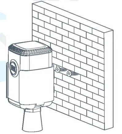
Wall Mounting
- Attach the mounting bracket to the wall and drill. (Around 16mm)
Note: The connecting line of two holes must be a horizon line. - Drive two screws into the wall at the marks using a screwdriver.
- Mount the device on the wall.

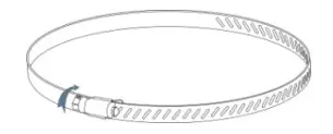
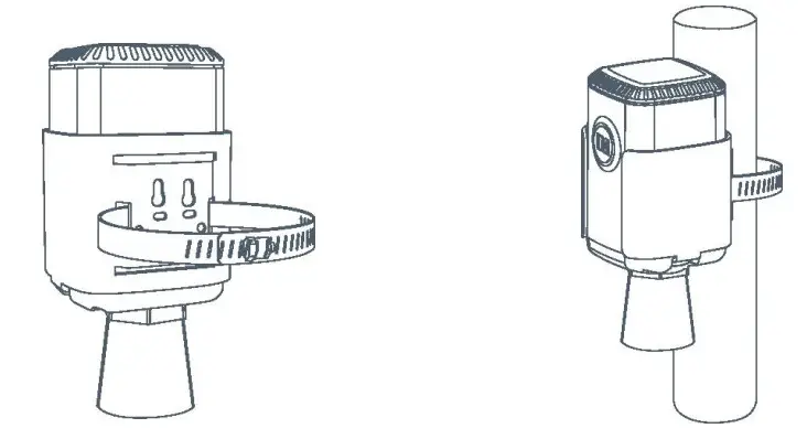
Pole Mounting
- Loosen the hose clamp by turning the locking mechanism counter-clockwise.

- Straighten out the hose clamp and slide it through the rectangular holes in the mounting bracket, and wrap the hose clamp around the pole.
- Use a screwdriver to tighten the locking mechanism by turning it clockwise.

DIN Rail Mounting
Use 2 pieces of M3 × 6 flat head Phillips screws to fix the DIN rail to the device, and then hang the DIN rail on the mounting bracket. It is necessary to choose a standard bracket. 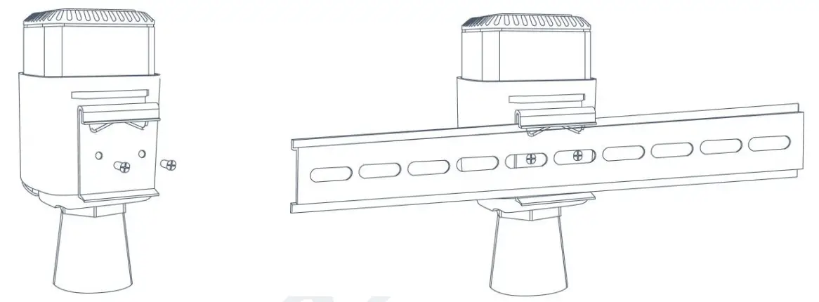
Turn-ON/OFF the Sensor
EM500-UDL can be turned ON/OFF via smartphone or computer with NFC (Near Field Communication) or a button. Select one of the following methods to turn on/off the sensor.
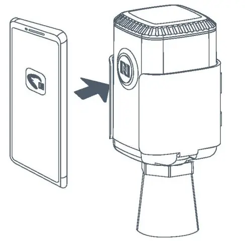
Turn-ON/OFF via Smartphone APP
- Download Ursalink configuration APP “Toolbox” and install it on your smartphone. The smartphone must support NFC.
- Enable NFC on the smartphone and open the APP.
- Attach the smartphone with NFC area to the device.
Note: Ensure the location of your smartphone’s NFC area and it is recommended to take off the phone case before using NFC.
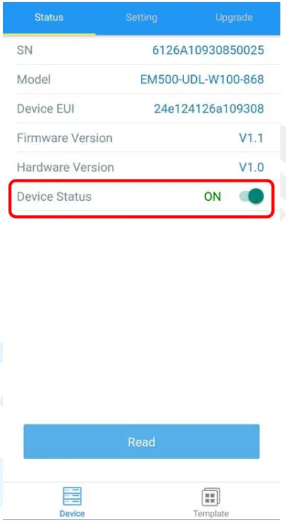
- Device information will be shown on the APP.
- Switch the button of Device Status to turn on or off the device.

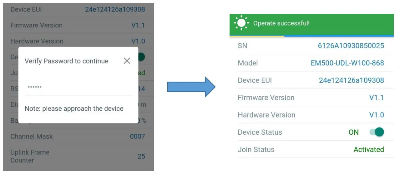
- Enter the correct password (default password: 123456) and wait a few seconds until APP shows “Operate Successfully!”.
Note: Keep the two devices close together and do not move them in order that you can get the best connectivity possible when turning them on or off via NFC. No response can be caused by long-distance, wrong location, or rapid movement.
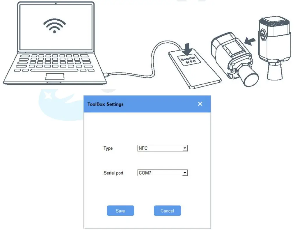
Turn-ON/OFF via PC Software
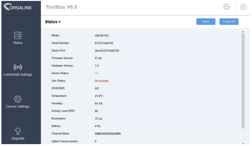
- Download Ursalink configuration software “Toolbox” and open the software.
- Connect the NFC reader to the computer and attach the device to the NFC reader.
- Select type as NFC and the serial port of the NFC reader, then click “save”.

- Device information will be shown on the software.

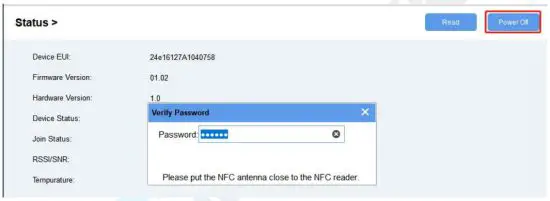
- Click “Power On” to turn on the device or “Power Off” to turn off the device.
- Enter the password (default password:123456) and press Enter key to change the device status.

- Remove screws on the bottom of EM500-UDL and take off the upper enclosure.
- Find the button beside the battery.
- Press the button until the LED blinks to turn on or off the device. (about 3 seconds)
Press the button until LED blinks rapidly to reset the device to factory default. (Over 10 seconds)
Sensor configuration
Ursalink EM500-UDL sensor can be monitored and configured via NFC technology. In order to protect the security of the sensor, password validation is required when turning on/off the sensor or changing configuration. Select one of the following ways to configure EM500-UDL sensors.
Configuration via Smartphone APP
Make sure Ursalink Toolbox APP is downloaded and installed on your smartphone.
Read Configuration
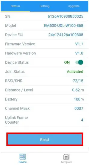
- Open APP “Toolbox” and click “Read” to read the current information of the device.

- Attach the smartphone with NFC area to the device until the APP shows “Read Successful!”.
 Note: Failing to read can be caused by long-distance, wrong location, or rapid movement.
 Note: Failing to read can be caused by long-distance, wrong location, or rapid movement.
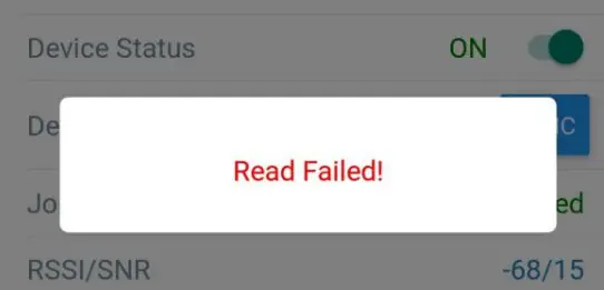
Write Configuration
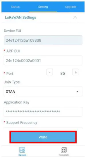
- Open APP “Toolbox” and go to the “Settings” page.
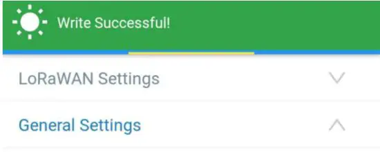
- Change parameters as required and click “Write”.
- Enter a password (default password: 123456).
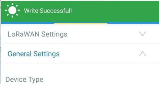
- Attach the smartphone with NFC area to the device and wait a few seconds until the APP shows
“Write Successful!”. The device will automatically re-join the network if LoRaWAN parameters are changed.
Note: Failing to write can be caused by long-distance, wrong location, or rapid movement.
Template Settings
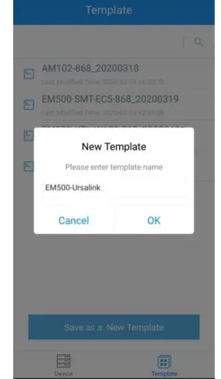
Template settings are used for easy and quick device configuration in bulk.
Note: Template function is allowed only for sensors with the same model and LoRa frequency band.
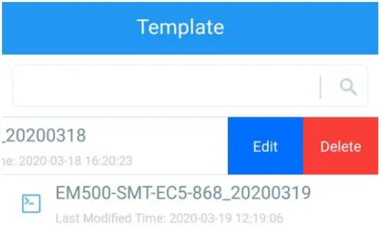
- Go to the “Template” page of the APP and save current settings as a template.

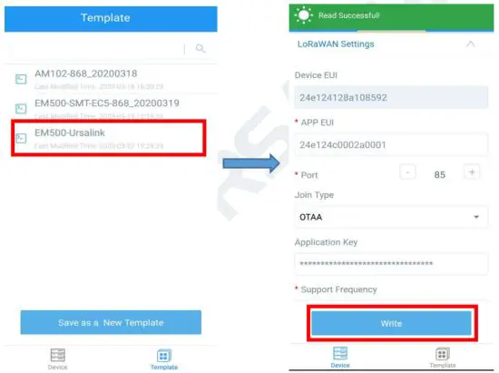
- Attach the smartphone with NFC area to another device.
- Select the template file from Toolbox APP and click “Write”.

- Enter a password for this device and keep the two devices close until the APP shows “Write successful!”.

- Slide the template item left to edit or delete the template.
Read Configuration
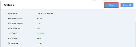
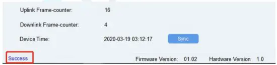
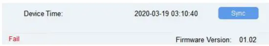
- Open software “Toolbox” and click “Read” to read the current information of the device.

- Attach the device to the NFC reader until Toolbox shows “success”.

Note: Failing to read can be caused by long-distance, wrong location, or rapid movement.
Write Configuration
- Go to the “Settings” page to change parameters as requirements and click “save”.
- Click “Write” and enter the correct password (default password: 123456).

- Press Enter key to write and attach the device close to the NFC reader until the “Write” button disappears. The device will automatically re-join the network if LoRaWAN parameters are changed.
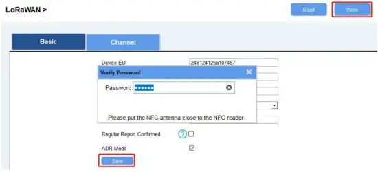
Note: Keep the two devices close and don’t move them in order that you can get the best connectivity possible when writing data via NFC. A bad connection can be caused by long-distance, wrong locations, or rapid movement.
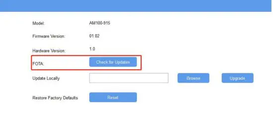
Upgrade
Upgrade Locally
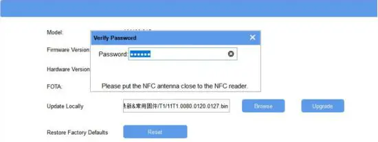
- Download firmware to your computer.
- Go to “Maintenance -> Upgrade” in Toolbox.
- Click “Browse” and select the firmware from the computer.
- Click “Upgrade” and enter the password of the device.
- Press Enter key to start the upgrade. The device will check if the firmware is correct. If it is correct, the firmware will be imported to the device to upgrade.
Note: Keep the two devices close and don’t move them in order that you can get the best connectivity possible when upgrading. Failing to upgrade can be caused by long-distance, wrong location, or rapid movement.
FOTA
- Make sure your computer can access the Internet.
- Click “Check for Updates” to search for the latest firmware via computer Internet and upgrade.
Note: Keep the two devices close and don’t move them in order that you can get the best connectivity possible when upgrading. Failing to upgrade can be caused by long-distance, wrong locations, or rapid movement.
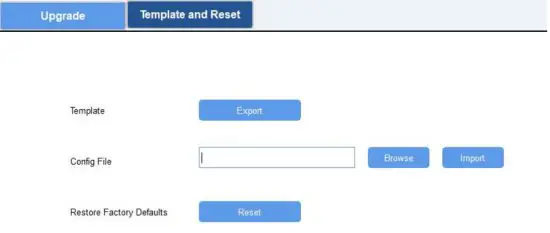
Template and Reset
Template Configuration
- Go to “Maintenance -> Template and Reset” in Toolbox.
- Click “Export” to save the current settings as a template.

- Click “Browse” to select the correct template from the computer.
- Click “Import” to import the template to the device.
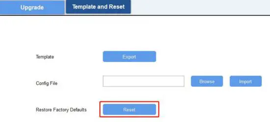
Reset
Click the “Reset” to reset the setting to factory default.
Sensor Parameters (for App and PC)
LoRa WAN Settings
Basic Settings-OTAA
Location:
Ursalink ToolBox(PC): LoRaWAN Settings → Basic
Ursalink ToolBox(APP): Device → Settings → LoRaWAN Settings
Basic Settings-OTAA
| Item | Description | Default |
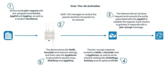
| App EUI | Enter the application EUI. The Network Server receives requests and consults the entity associated with the APP EUI to validate the request. If permission is granted, it responds with a join-accept message. | 24e124c000 2a0001 |
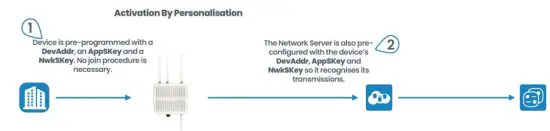
| Join Type | Select from: “OTAA” and “ABP”. OTAA: Over-the-Air Activation. For over-the-air activation, end devices must follow a joint procedure prior to participating in data exchanges with the network server. An end device has to go through a new join procedure every time it loses the session context information. ABP: Activation by Personalization. Under certain circumstances, end devices can be activated by personalization. Activation by personalization directly ties an end device to a specific network bypassing the join request – join accept the procedure. | OTAA |
| Application Key | Enter the application key. Whenever an end device joins a network via over-the-air activation, the application key is used to derive the Application Session key. | 5572404c69 6e6b4c6f526 13230313823 |
| Confirmed Mode | After sending the attribute/data/battery packets to the network server, the device will resend these packets if it does not receive an ACK bit from the Network Server. Note: If the device doesn’t receive ACK for a long time, the device will resend confirmed packets 3 times at most. However, the device will resend the attribute package all the time. | Disabled |
| ADR | ADR: Adaptive Data Rate. Enabled: The Network Server will adjust the data rate by MAC command. Disabled: Whatever how the signal quality is, the Network Server will not adjust the data rate of the device. | Enabled |
Basic Settings-ABP
Location:
Ursalink ToolBox(PC): LoRaWAN Settings → Basic
Ursalink ToolBox(APP): Device → Settings → LoRaWAN Setting
| Item | Description | Default |
| App EUI | Enter the application EUI. The Network Server receives requests and consults the entity associated with the APP EUI to validate the request. If permission is granted, it responds with a join-accept message. | 24e124c0002 a0001 |
| Join Type | Select from: “OTAA” and “ABP”. OTAA: Over-the-Air Activation. For over-the-air activation, end devices must follow a joint procedure prior to participating in data exchanges with the network server. An end device has to go through a new join procedure every time it has lost the session context information. ABP: Activation by Personalization. Under certain circumstances, end devices can be activated by personalization. Activation by personalization directly ties an end device to a specific network bypassing the join request – join accept the procedure. | OTAA |
| Device Address | Enter the device address. The device address identifies the end device within the current network. | The 5th to 12th digits number of SN |
| Network Session Key | Enter the network session key of the device. The network session key is specific for the end device. It is used by the end device to calculate the MIC or part of the MIC (message integrity code) of all uplink data messages to ensure data integrity. | 5572404c696 e6b4c6f5261 3230313823 |
| Application Session Key | Enter the application session key of the device. The AppKey is an application session key specific to the end device. It is used by both the application server and the end device to encrypt and decrypt the payload field of application-specific data messages. | 5572404c696 e6b4c6f5261 3230313823 |
| Confirmed Mode | After sending the attribute/data/battery packets to the network server, the device will resend these packets if it does not receive an ACK bit from the Network Server. Note: If the device doesn’t receive ACK for a long time, the device will resend confirmed packets 3 times at most. However, the device will resend the attribute package all the time. | Disabled |
| ADR | ADR: Adaptive Data Rate. Enabled: The Network Server will adjust the data by MAC command. Disabled: Whatever how the signal quality is, the Network Server will not adjust the data rate of the device. | Enabled |
Channel Settings
Location:
Ursalink ToolBox(PC): LoRaWAN Settings → Channel
Ursalink ToolBox(APP): Device → Settings → LoRaWAN Settings
Note: Make sure the LoRa channel configuration of EM500-UDL matches the LoRaWAN gateway.
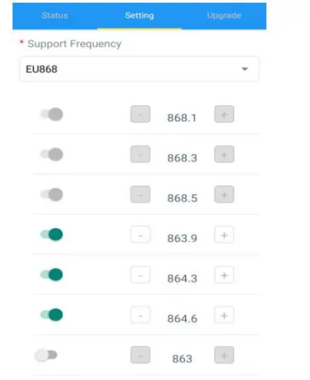
Lora frequency configuration is as follows if the sensor LoRa frequency is one of EU433/EU868/RU864/IN865/AS923/KR920:
Lora frequency configuration is as follows if the sensor LoRa frequency is one of CN470/US915/AU915:
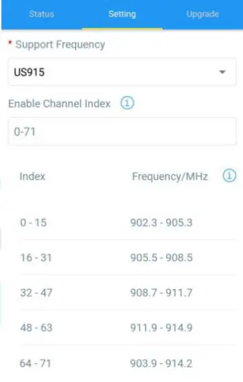
Enter the index of the channel to be enabled in the input box, separated by commas.
Example:
1, 40: Enabling Channel 1 and Channel 40
1-40: Enabling Channel 1 to Channel 40
1-40, 60: Enabling Channel 1 to Channel 40 and Channel 60
All: Enabling all channels
Null: Indicates that all channels are disabled
Note:
For US915:
64 channels numbered 0 to 63 utilize LoRa 125 kHz BW starting at 902.3 MHz and incrementing linearly by 0.2 MHz to 914.9.
8 channels numbered 64 to 71 utilize LoRa 500 kHz BW starting at 903.0 MHz and incrementing linearly by 1.6 MHz to 914.2.
For AU915:
64 channels numbered 0 to 63 utilize LoRa 125 kHz BW starting at 915.2 MHz and incrementing linearly by 0.2 MHz to 927.8.
8 channels numbered 64 to 71 utilizing LoRa 500 kHz BW starting at 915.9 MHz and incrementing linearly by 1.6 MHz to 927.1.
For CN470:
80 channels numbered 0 to 79 utilize LoRa 125 kHz BW starting at 470.3 MHz and incrementing linearly by 0.2 MHz to 486.1.
16 channels numbered 80 to 95 utilize LoRa 125 kHz BW starting at 486.3 MHz and incrementing linearly by 1.6 MHz to 489.3.
Device Settings
General
Location:
Ursalink ToolBox(PC): Device Settings → General
Ursalink ToolBox(APP): Device → Settings → General Settings
Device General Settings
| Item | Description | Default |
| Device Type | Show the type of device. | Null |
| Reporting Interval | The sensor reports the sampling data at regular intervals. Range: 5-30 (mins) | 10 |
| Change Password | Change the password used for changing device status and writing configuration. | Disabled |
Data Calibration
Location:
Ursalink ToolBox(PC): Device Settings → Data Calibration Settings
Ursalink ToolBox(APP): Device → Settings → Data Calibration Settings
Note: It is recommended to do the calibration before using the device.
Data Calibration Settings
| Item | Description | Default |
| Enable | Enable calibration. | Disabled |
| Current Raw | The current value. | Null |
| Distance/Level | Enter the calibration value for distance/level. Note: only two decimal is allowed. | Null |
| Calibration | Adjusted value. | Null |
| Final Value | Enable abnormal value prevention. | Disabled |
| Prevention | ||
| Set Value | Setting value=| A – B | / C * 100%. ( A=current measured value; B=previous measured val ue; C=maximum range) If the current measured value exceeds the set value after calculation by the previous formula, it is abnormal al and the device will measure again. | Null |
Threshold
Location:
Ursalink ToolBox(PC): Device Settings → Threshold Settings
Ursalink ToolBox(APP): Device → Settings → Threshold Settings
Threshold Settings
| Item | Description | Default |
| Distance/Level | Enable: The device will send the latest distance/level value to the network server if it goes above/below distance/level thresholds. | Disabled |
| Over | Enter the maximum distance/level threshold. | Null |
| Below | Enter the minimum distance/level threshold. | Null |
Example: Set the “Lockout Time” for 10min, “Duration” for 5min.
The device will report the detected value immediately when the value reaches the threshold and last for 5mins. After that, the device will check the detected value every 10 mins, and report the value again if it reaches the threshold and lasts for 5mins.
Sensor Management via Ursalink Cloud
Ursalink cloud is a comprehensive platform that provides multiple services including device remote management and data visualization with the easiest operation procedures.
Ursalink Cloud Registration
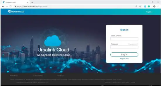
Register and log in to Ursalink Cloud.
Ursalink Cloud URL: https://cloud.ursalink.com/login.html
Add a Ursalink LoRaWAN Gateway
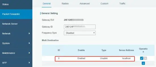
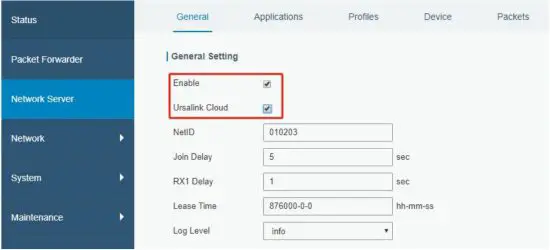
- Enable “Ursalink” type network server and “Ursalink Cloud” mode in gateway web GUI.
Note: Ensure gateway has accessed the Internet.
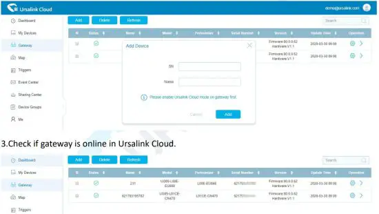
- Go to “My Devices->Gateway” of Ursalink Cloud and click “Add” to add a gateway to Ursalink Cloud via SN.

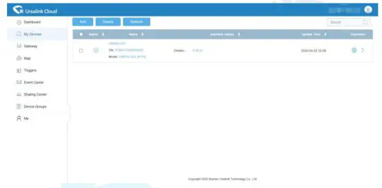
Add EM500-UDL to Cloud
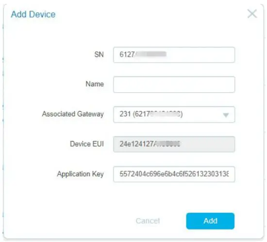
- Go to “Device->My Devices” and click “Add Device”. Fill in the SN of EM500-UDL and select the associated gateway.

- After EM500-UDL is connected to Ursalink Cloud, Click data on Ursalink cloud.

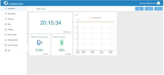
- Go to the “Dashboard” page to add the dashboard.

FCC Caution:
Any changes or modifications not expressly approved by the party responsible for compliance could void the user’s authority to operate the equipment.
This device complies with part 15 of the FCC Rules. Operation is subject to the following two conditions: (1) This device may not cause harmful interference, and (2) this device must accept any interference received, including interference that may cause undesired operation.
IMPORTANT NOTE:
Note: This equipment has been tested and found to comply with the limits for a Class B digital device, pursuant to part 15 of the FCC Rules. These limits are designed to provide reasonable protection against harmful interference in a residential installation. This equipment generates, uses, and can radiate radio frequency energy and, if not installed and used in accordance with the instructions, may cause harmful interference to radio communications. However, there is no guarantee that interference will not occur in a particular installation. If this equipment does cause harmful interference to radio or television reception, which can be determined by turning the equipment off and on, the user is encouraged to try to correct the interference by one or more of the following measures:
- Reorient or relocate the receiving antenna.
- Increase the separation between the equipment and receiver.
- Connect the equipment into an outlet on a circuit different from that to which the receiver is connected.
- Consult the dealer or an experienced radio/TV technician for help.
FCC Radiation Exposure Statement:
This equipment complies with FCC radiation exposure limits set forth for an uncontrolled environment. This equipment should be installed and operated with a minimum distance of 20cm between the radiator& your body.


