![]() USER MANUAL
USER MANUAL
MODEL NUMBER:
FI-EZB-15NV
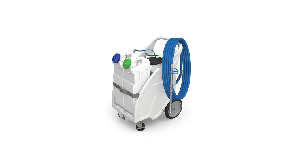
EZBlend™ Foam Unit
Original Instructions)
READ ALL INSTRUCTIONS BEFORE OPERATING EQUIPMENT
FI-EZB-15NV EZBlend Foam Unit
![]() WARNING
WARNING
![]()
Read this manual completely and understand the machine before operating or servicing it.
- Read all instructions before installing or operating unit.
- Always wear appropriate personal protective equipment (PPE) when operating or servicing unit.
- Always follow all chemical safety precautions and handling instructions provided by the chemical manufacturer and Safety Data Sheet (SDS).
- If this unit is modified or serviced with parts not listed in this manual, dilution rates may vary, or the unit may not operate correctly.
- Never point the discharge wand at yourself, another person, or any object you do not want covered in chemical.
- Always depressurize unit after use (as described in the After Use Instructions). Always store unit depressurized, with the discharge ball valve in the closed position.
- Do not exceed an incoming air pressure of 100 psi (7 bar).
- Do not exceed a fluid temperature of 100˚F (37˚C).
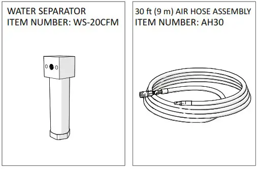
- Only use clean and dry air. Air must be filtered and free of moisture or pump life will be diminished. If needed, install a water separator (WS- 20CFM) before the unit.
- Do not use an air lubricator before the unit.
PROTECT THE ENVIRONMENT
Please dispose of packaging materials, old machine components, and hazardous fluids in an environmentally safe way according to local waste disposal regulations.
![]() Always remember to recycle.
Always remember to recycle.
*Specifications and parts are subject to change without notice.
REQUIREMENTS
| Compressed air requirements | 40-80 psi (3-5 bar) with 5-10 cfm (141- 283 limin) |
| Liquid temperature range | 40-100°F (4.4-37°C) |
| Chemical compatibility | This unit is specifically configured for use with Sterilex liquid products. |
SPECIFICATIONS
| Power type | Compressed air |
| Chemical pickup type | Draws from concentrated product |
| Dilution ratio range (Chemical A:Chemical B: Water)’ | 12.8-16 fl. oz. : 12.8-16 fl. oz. : 1 gallon (378.5-473.2 ml : 378.5-473.2 ml : 3.78 liters) |
| Number of products unit can draw from | Two products, simultaneously |
| Suction line length/ diameter | Two transparent suction lines, one blue and one green, each 4 ft. (1.2 m) long with 1/4 in. (6.4 mm) inside diameter; with quick disconnect fittings for chemical jugs |
| Capacity | 15 gallons (56.78 liters) of water; Up to 10 gallons (37.85 liters) of concentrate |
| Discharge hose diameter/length | 30 ft. (9 m) hose, with 3/4 in. (19 mm) inside diameter |
| Discharge wand/tip type | 12 in. (30.48 cm) stainless steel wand and ball valve with 65′ fan tip; includes stainless quick connects |
| Output distance | 10-12 ft. (3-4.6 m) |
| Output volume | 15-20 gal/min (56.8-75.71/min) |
| Flow rate• | 2 gal/min (7.6 l/min) |
| Pump seals | Viton |
| Wheel type | Two 10 inch non-marking wheels, two 5 inch casters with lock |
*Dilution rates and flow rates given are based on chemical with viscosity of water and factory air pressure settings.
SPECIAL INSTRUCTIONS
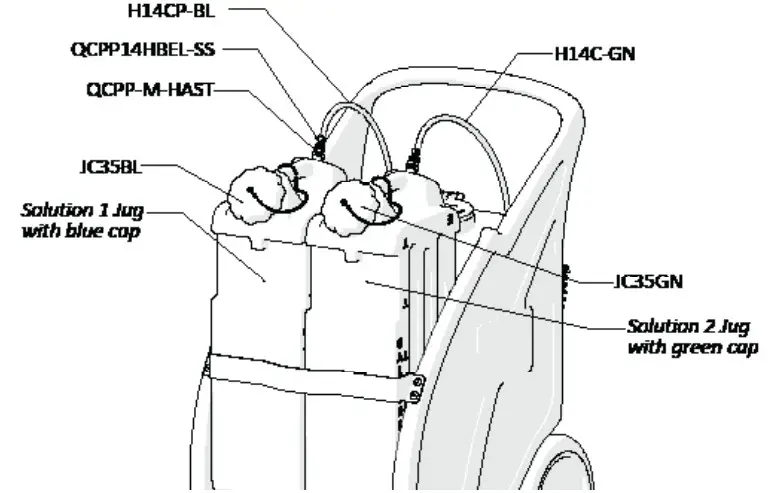
This unit is specifically designed for use with Sterilex two-part liquid products. The unit is calibrated to achieve dilution rates as recommended by Sterilex of 12.8oz-16oz Solution 1: 12.8oz-16oz Solution 2: 1 gal water. One jug with a blue cap is labeled “Solution 1/Disinfectant Products” and should only be used with those Sterilex products categorized as “Solution 1/Disinfectant” products below. The other jug with a green cap is labeled “Solution 2/Activator Products” and should only be used with those Sterilex products categorized as “Solution 2/Activator” products below. Modifications to the unit will result in varied dilution rates that may minimize effectiveness of solutions or result in off label product usage.
ALWAYS AFFIX STERILEX CHEMICAL JUG TAGS TO EACH JUG. CONTACT YOUR STERILEX PRODUCT CHEMICAL VENDOR FOR JUG TAGS.
ACCEPTABLE PRODUCTS
| Sterilex “Solution 1/Disinfectant” Products | Sterilex “Solution 2/Activator” Products |
| Sterilex® Ultra Disinfectant Cleaner Solution 1 (US) | Sterilex® Ultra Activator Solution (US) |
| Sterilex® Ultra CIP (US) | Ultra Soft Metal Activator (US) |
| Sterilex® Ultra-Kleen Solution: Solution 1 (Canada) | Sterilex® Ultra-Kleen Solution: Solution 2 (Canada) |
| Sterilex® Ultra Soft Metal Disinfectant Cleaner (Canada) | Sterilex® Ultra Soft Metal Activator (Canada) |
Operation Instructions:
- Remove unit from packaging.
- Using EZBlend Chemical Dispensing Unit or other dispensing system:
a. Fill 5 gallon jug with blue cap with Sterilex “Solution 1/Disinfectant” product and secure cap.
b. Fill 5 gallon jug with green cap with Sterilex “Solution 2/Activator” product and secure cap.
NOTE: Refer to the Acceptable Products chart if needed. - Connect the chemical intake lines to the chemical containers.
a. Connect the blue chemical intake line to the blue cap jug.
b. Connect the green chemical intake line to the green cap jug. - Fill the 15 gallon tank with water.
- Verify that the valve (PVCV34FM) at the base of the suction line is open, to allow fluid into the suction line.
- With the discharge ball valve (HV60) in the closed position, plug an air line into the air fitting (AP25).
- Slowly open the discharge ball valve (HV60) to begin foaming. The discharge ball valve (HV60) should be completely open while foaming.
- Unit is pre-set to a standard needle valve (NV14Y) setting to deliver product at labeled rate. If adjustment is needed for foam consistency or dilution, see Adjustment for Foam Consistency and Dilution Instructions.
NOTE: It is a best practice to always confirm chemical dilution with titration after adjusting needle valve.
Use titration kit available from Aqua Phoenix Scientific (US part number – TK3319-Z; Canada part number – TK3319FR) when titrating Sterilex products. - To stop foaming, close the discharge ball valve (HV60). Disconnect the air line from the air fitting (AP25) and relieve any remaining pressure in the system by opening the discharge ball valve (HV60).
After Use Instructions:
- It is recommended to flush the unit with fresh water.
- Disconnect both blue and green chemical intake lines from the chemical jugs.
- Connect the air line to the air fitting (AP25) and open the discharge ball valve (HV60) to dispense water for at least one minute.
- Close the discharge ball valve (HV60). Disconnect the air line from the air fitting (AP25) and relieve any remaining pressure in the system by opening the discharge ball valve (HV60).
- Close the ball valve (HV60) after all pressure has been relieved from the system. Store the unit with the discharge ball valve (HV60) in the closed position.
Maintenance Instructions:
To keep your foam unit operating properly, periodically perform the following maintenance procedures:
Note: Before performing any maintenance, ensure that the unit has been disconnected from the air and water supply and depressurized according to the After Use Instructions.
- Inspect the pump (P56V) for wear and leaks.
- Inspect all hoses for leaks or excessive wear. Make sure all hose clamps are in good condition and properly secured.
- Replace the filter (AFR25) located within the air regulator (R25) as needed. Clean by unthreading the air regulator bowl (ABR25) from the air regulator (R25).
- Check the chemical metering tips, suction lines and strainer for debris and clean as needed.
- Drain your air compressor tank on a regular basis to help extend pump life. An air source with a high moisture content will accelerate pump wear. Note: If your air source has a high moisture content, you may wish to install a water separator (WS-20CFM) before the unit.
Troubleshooting Instructions:
- Check to ensure that the discharge hose is uncoiled properly, and that there are no kinks that could obstruct fluid flow.
- Check the air regulator bowl (ABR25) and air filter (AFR25) for debris such as water, oil, or rust particles. Clean by unthreading the air regulator bowl (ABR25) from the air regulator (R25).
- If the needle valve (NV14Y) is open too far, the pump (P56V) may cycle improperly due to lack of air pressure.
- If air passes through the pump (P56V) without cycling, the pump needs to be replaced.
- If solution backs up into the air regulator bowl (ABR25), the check valve (CV38) needs to be replaced.
- If foam comes out wet, no matter where the needle valve (NV14Y) is positioned, the check valve (CV38) may need to be replaced.
- Check for proper air pressure on the air gauge (AG100). The air regulator (R25) is factory set at 50 psi (3.4 bar). Operating range is 40 to 80 psi (3 to 5 bar) with 5 to 10 cfm (141 to 283 l/min).
- If the unit operates at a reduced pressure:
- Check the air compressor supplying the unit. If the pressure is less than 40 psi, turn the unit off until the compressor can catch up.
- If the air supply is 50 psi (3.4 bar) or above, check the air gauge (AG100), which should read near 50 psi (3.4 bar). If the air gauge reads more or less than 50 psi (3.4 bar), adjust the pressure by turning the knob on the top of the air regulator (R25).
- If both of the above are okay, the stainless steel mixing mesh (SS-MESH) could be plugged. Remove and clean it by following the instructions below:
1. Be sure the foam unit is not plugged into an air supply and be sure to relieve all stored pressure in the unit by having the ball valve (HV60) in the open position.
2. Remove the stainless hose barb (HBSS1234) from the tee fitting (SST12HB38).
3. Remove the screen and the mixing mesh from inside the tee fitting (SST12HB38).
4. Clean any particles from the mixing mesh and the screen.
5. Replace the mixing mesh and then the screen into the back of the tee and screw the stainless adaptor back into the tee. It is recommended to use a pipe thread sealant when reinstalling the stainless adaptor back into the tee fitting (SST12HB38). If the mixing mesh has a lot of foreign particles in it, make sure the strainer (STR38-IL) is still in place.
- Check the chemical metering tips, suction lines and strainer for debris or damage. Clean or replace as needed. To prevent damage to the unit, the strainer must always be used.
- If concentrated product is back flowing into the water tank, the check valve (CV38-AP) needs to be replaced.
Adjustment for Foam Consistency and Dilution Instructions:
NOTE: Always confirm chemical dilution with titration after adjusting needle valve.
- If needle valve (NV14Y) adjustment is needed for better foam consistency, while the unit is running and discharging product, adjust the needle valve as needed to regulate the wetness or dryness of the foam following the steps.
- For minor adjustment, turn the needle valve handle (NV14Y) in 1/8 turn increments allowing 30 seconds between adjustments, until desired consistency of foam is achieved.
- Open needle valve in counter-clockwise direction for dryer foam.
- Close needle valve in clockwise direction for wetter foam.
- If your dilution is not within the labeled rate:
- To decrease concentration, open needle valve counter-clockwise.
- To increase concenration, close needle valve clockwise.
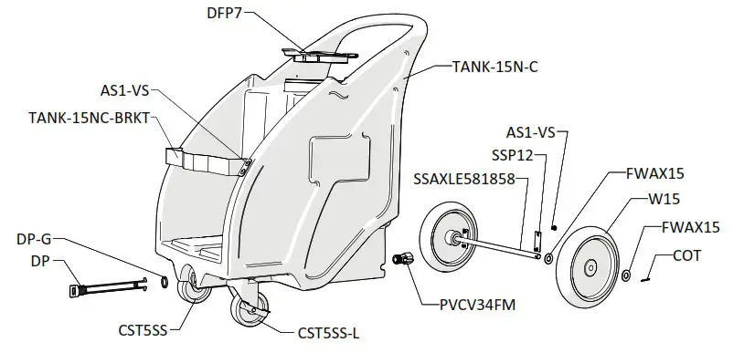
TANK ASSEMBLY
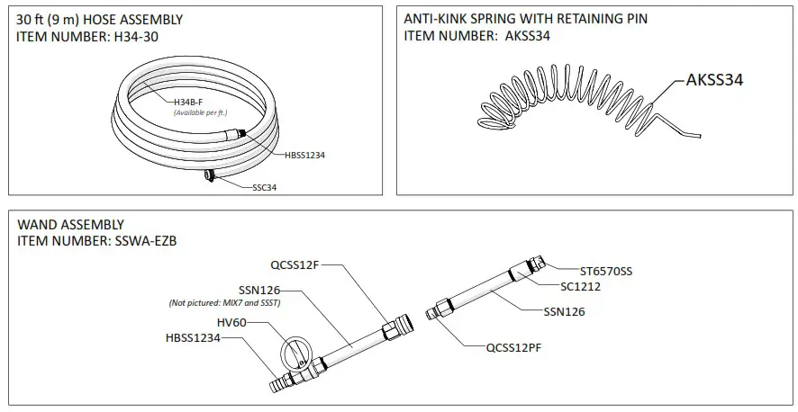
HOSE AND WAND ASSEMBLY
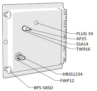
BACK PLATE ASSEMBLY
Inside View
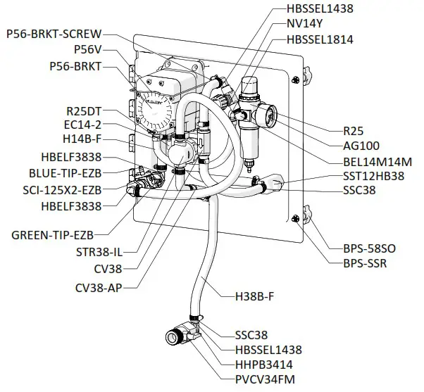
Outside View
OPTIONAL COMPONENTS
CHEMICAL JUGS
Solution 1 Jug: J5BLS
Solution 2 Jug: J5GNS
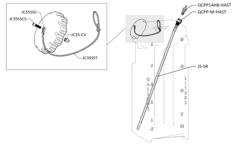
JUG ASSEMBLY
| ITEM NUMBER | DESCRIPTION |
| AG100 | 1.5 INCH DRY MODEL 20 DUAL SCALE GAUGE |
| AKSS34 | SS ANTI-KINK SPRING FOR 3/4 INCH HOSE |
| AP25 | AIR FITTING 1/4 MPT X PLUG-BRASS |
| AS1-VS | 1/4-20 X 1/2 PHIL TRUSS MACH SCREW 19-8 W/516 ORANGE VIBRASEAL PATCH |
| B8X58 | 8-15 x 1/2 FLAT PHIL TY-A 18-8 PLN |
| BEL14M14M | ELBOW 1/4in MPT X 1/4in MPT |
| BLUE-TIP-EZB | BLUE METERING TIP FOR EZB APPLICATION |
| BPS-58S0 | Back Panel Screw – 5/8 inch with Stand Off |
| BPS-SSR | 1/4 INCH PUSHNUT BOLT RETAINER STAINLESS STEEL |
| COT | 1/8 X 1 COTTER PIN 18-8 S/S |
| CSTSSS | 5in S.S. SWIVEL CASTER WITH 4 IN WHEEL |
| CSTSSS-L | 5in S.S. SWIVEL CASTER WITH 4 IN WHEEL AND LOCK |
| CV38 | PVC CHECK VALVE 3/8 BARBS – SS SPRING |
| CV38-AP | WHITE PVC CHECK VALVE 3/8 BARBS – HASTELLOY SPRING – TEFLON BALL |
| DFP7 | 7 INCH HINGED CAP ASSEMBLY – INCLUDES BLACK CAP, LID FLANGE AND HINGE PIN |
| DFP7-C | 7 INCH FILL CAP POLYETHYLENE BLACK |
| DFP7-F | 7 INCH TANK LID FLANGE POLYETHYLENE |
| DFP7-PIN | HINGE PIN FOR 7 INCH FILL CAP AND FLANGE |
| DP-A | DRAIN PLUG ASSEMBLY FOR NATURAL PORTABLE UNITS |
| DP | FRONT DRAIN PLUG FOR PORTABLE UNIT POLYETHYLENE |
| DP-G | FKM LATHE CUT 60 DUROMETER |
| EC14-2 | OETIKER CLAMP 13.8 |
| EC75 | OETIKER CLAMP FOR 3/4IN HOSE |
| F34SS-L | SS CRIMP FERRULE 1.90inches X 1.5 inches LONG |
| FWAX15 | FLAT AXLE WASHER |
| FWP12 | 7/8 ID X 1.5 OD X 0.05 THK SSFW |
| FWP14 | C-816 1/2in SS WASHER |
| GREEN-TIP-EZB | GREEN METERING TIP FOR EZB APPLICATION |
| H14B-F | 1/4 INCH BLUE HOSE-HYBRID TPE-Available per ft. |
| H14C | 1/4in ID (3/8 in OD) CLEAR POLYVINYL TUBING -Available per ft. |
| H14C-BL | 1/4in ID (3/8 in OD) CLEAR BLUE POLY TUBING -Available per ft. |
| H14C-GN | 1/4in ID (3/8 in OD) CLEAR GREEN POLY TUBING -Available per ft. |
| H34B-F | 3/4 INCH BLUE HOSE-HYBRID TPE-Available per ft. |
| H38B-F | 3/8 INCH BLUE HOSE-HYBRID TPE-Available per ft. |
| H38C | 3/bin CLEAR PVC TUBING – Available per ft. |
| HBELF3838 | HOSE BARB ELBOW 3/8″ BY FPT 3/8″ |
| HBSS1234 | STAINLESS HOSE BARB 1/2 MPT X 3/4 BARB |
| HBSS1438 | STAINLESS HOSE BARB 1/4 MPT X 3/8 BARB |
| SC1212 | S.S. COUPLER 1/2in BY 1/2in |
| SCI-125X2-EZB | STAINLESS CHEMICAL INJECTOR-.125 ORFICE-DUAL BARB GREEN & BLUE-EZBLEND |
| SSA14 | STAINLESS ADAPTOR 1/4 MPT X 1/4 FPT |
| SSAXLE581858 | SS AXLE .625 DIA x 18.62 IN |
| SSC14 | STAINLESS SCREW BAND CLAMP FOR 1/4 IN HOSE |
| SSC38 | STAINLESS SCREW BAND CLAMP FOR 3/8 IN HOSE |
| SSN126 | STAINLESS PIPE NIPPLE 1/2 MPT X 1/2 MPT- 6 IN LONG |
| SSP12 | STAINLESS STEEL AXLE PLATE – 2.5 inch X 1 inch – 2 HOLE |
| SST12HB38 | STAINLESS TEE 1/2 FPT 3/8 BARB – WITH SSST AND SSMESH |
| SS-MESH | STAINLESS STEEL MESH WITH SSST FOR REPLACEMENT |
| HBSSEL1438 | STAINLESS HOSE BARB 1/4 MPT X 3/8 BARB ELBOW |
| HBSSEL1814 | STAINLESS HOSE BARB 1/8 MPT X 1/4 BARB ELBOW |
| HHPB3414 | HEX HEAD POLY BUSHING 3/4 MPT X 1/4 FPT |
| HV60 | 1/2IN STAINLESS BALL VALVE – WELDED NUT |
| 15 | 5 GALLON NATURAL JUG |
| 15-SR | 5 GALLON SUCTION REPLACEMENT (INCLUDES QUICK CONNECTS) |
| JC35BL | BLUE 3.5 INCH ONE WAY VENTED CAP POLYPROPYLENE WITH GASKET AND CHECK VALVE |
| JC35-CV | EPDM CHECK VALVE FOR NON LOCKING JUG CAP |
| JC35GN | GREEN 3.5 INCH ONE WAY VENTED CAP POLYPROPYLENE WITH GASKET AND CHECK VALVE |
| JC35SSC | 304 SS END COUPLING FOR SIZE 8-10, ROUND BEAD CHAIN |
| JC35SSCS | SOCKET HEAD CAP SCREW-10-32 MPT-3/4IN LONG-VENTED |
| JC35SST | ROUND BEAD CHAIN, TYPE 304 STAINLESS STEEL, #10 |
| JC-G35 | JUG CAP GASKET 3.5 INCH CAP EPDM |
| MIX7 | 7 INCH WIRE TWISTED BRUSH-STAINLESS STEEL-13.SIN OVERALL LENGTH |
| NV14Y | FLOW CONTROL VALVE – INCLUDES BLACK KNOB |
| P203CT-FS | FOOT STRAINER FOR THE P203CT |
| P56V | PUMP WITH VITON SEALS – INCLUDES HOSE BARBS, AIR FITTING, AND EXHAUST BARB |
| 20756103B | Polypro G57 Air Port x HB Straight, w/ Viton o-ring |
| HB14P | 1/4in BRASS HB AIR FITTING /G57/P56 |
| SSST | SCREEN DISC .687 DIA. 10 X 10 MESH @ .020 DIA. 300 SERIES |
| ST6570SS | SPRAY TIP-65 DEGREE-7.0 GPM-1/2 MPT-STAINLESS STEEL |
| STR38-IL | IN LINE STRAINER-3/8 BARB-EPDM GSKT-20 MESH SS |
| TANK-15N-C | 15 GALLON CONCENTRATE TANK NATURAL IN COLOR |
| TANK-15NC-BRKT | SS BRACKET FOR TANK-15NC |
| TLCLAMP12 | Tefzel Loop Clamp for 1/2″ Outside Diameter |
| TW916 | 1/2 INT TOOTH L/W 410SS |
| W15 | NONMARKING WHEEL FOR PORTABLE UNITS |
Model No.: FI-EZB-15NV
10052022


