ECOLAB XP Foamer User Manual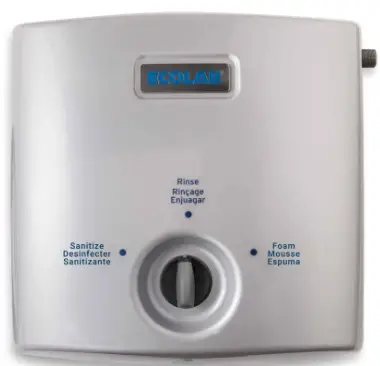
IMPORTANT SAFETY INSTRUCTIONS
WARNING
When using electric appliances, basic precautions should always be followed, including the following:
- Read all instructions before using the appliance.
- To reduce the risk of injury, close supervision is necessary when an appliance is used near children.
- Do not touch moving parts.
- Only use attachments recommended or sold by the manufacturer.
- Do not use outdoors.
Exception: This item is not required if the appliance has been evaluated for outdoor ude. - For a cord-Connected appliance, the following shall be included:
- To disconnect, turn all controls to the off (“O”) position, then remove plug from outlet.
- Do not unplug by pulling the cord. To unplug,grasp the plug, not the cord.
- Unplug from outlet when not in use and before servicing or cleaning.
- Do not operate any appliance with a damaged cord or plug, or after appliance malfunctions or if dropped or damaged in any manner. Return appliance to the nearest authorized service facility for examination, repair, or electrical or mechanical adjustment.
- For a portable appliance – To reduce the risk of electrical shock, do not put XP Foamier in water or other liquid. Do not place or store appliance where it can fall or be pulled into a tub or sink.
- For a grounded appliance – connect to a properly grounded outlet only. See Grounding Instructions.
Symbol
 | Instruction for Use – read before Us |
 | Wear glasses when using the unit. |
 | Wear gloves and suitable clothing when using the unit. |
 | Note: A potentially damaging situation. Possible consequences: The product or something in its vicinity could be damaged. Prevention. |
 | Caution: A dangerous situation. ‘Possible consequences: light or minor injuries. Can also be used in warn against damage to property or other goods prevention. |
| Warning: A Potentially dangerous situation. Possible consequences: Death or severe injury Prevention. |
| Danger: A dangerous situation. ‘Possible consequences: Death or severe injury Prevention. |
 | Danger of Electrocution Hazard and Electric shock. |
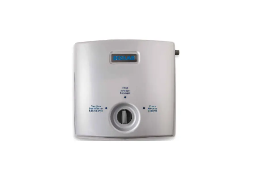
Description
The XP Foamier unit is a complete hygiene station for foaming, rinsing and disinfecting. The unit requires sufficient supply of water, compressed air and detergent or disinfectant.
The unit is tested and approved to operate with a wide range of chemical products.
Using Hygiene Chemicals:
The Griff unit can be used with foam detergents and disinfectants.
Do not change the settings made or recommended by the supplier of the hygiene chemicals.
The supply of detergents and disinfectants is done from cans with chemical products, mounted below the unit.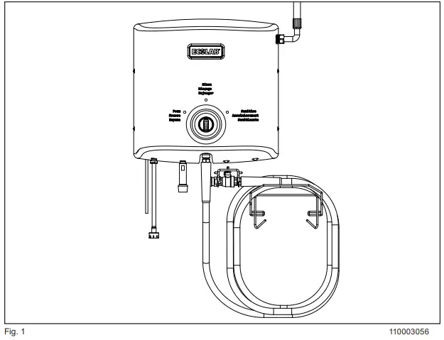
Layout for XP FOAMER.
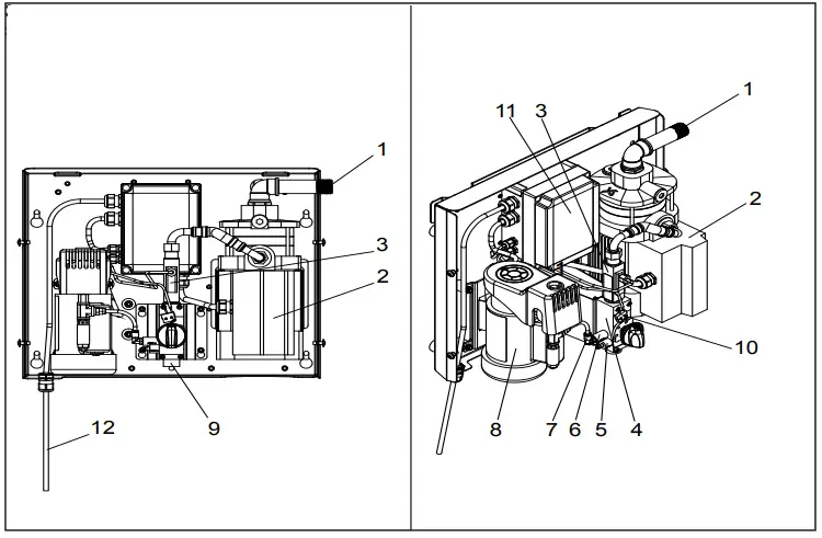
- Water inlet
- Pump
- Flow Switch
- Injector block
- Chemical inlet, block
- Sanitizer inlet, block
- Air inlet, block
- Compressor
- Water outlet
- Switch, Compressor
- Control box
- Power supply
Operating Diagrams
according to ISO14617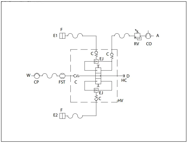
- F. Filter.
- FST. Flow-switch and -trigger.
- C. Check valve.
- CP. Centrifugal pump.
- EJ. Ejector.
- HV. Hydraulic valve.
- HC. Hose connection.
- A. Air supply.
- D. Outlet.
- E. Inlet, detergent.
- W. Water inlet.
- CO. Compressor
- RV. Regulating valve
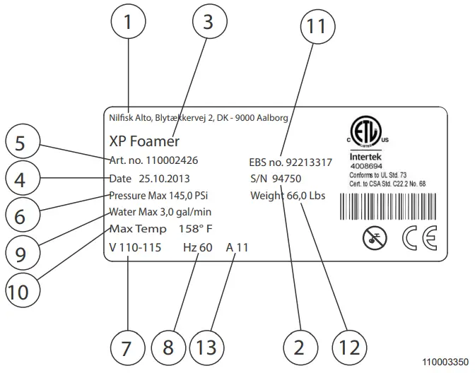
Identification Plate
- Producer
- Serial No.
- Type
- Date
- Article No.
- Maximum pressure
- Supply voltage
- Frequency
- Maximum water consumption
- Maximum temperature
- Customer Article no
- Weight

General information
For safety reasons it is important to read this manual before mounting this equipment. In addition, the legislation in force at the time of purchase must always be considered in connection with the installation and mounting of this equipment, no matter the contents of this manual.
If there are matters of dispute please contact your dealer. This equipment is produced and tested by specially qualified personnel, following approved instructions to ensure our high level of product quality. After the product is finished and tested it is manually inspected with the ultimate test carried out just before the product is released for shipping. To obtain our high level of quality
and long life we use stainless steel parts. These parts, in defiance of our manual inspections may still have some sharp edges, which can present a cut hazard. Therefore it is advised always to use protective gloves and show caution when installing the equipment.
The unit is UL/CSA listed.
Preparation
Wall version:
Identify what type of wall the unit will be mounted on.
The installation procedure for the most common wall types is described in the installation guide.
Make sure that the walls carrying capacity is sufficient.
Mobile version:
Identify a suitable place for the unit within the reach of the inlet hose.
Make sure the floor is level.
| Note: The pipeline must be rinsed through before the system is connected. |
| Note: Remove cover before the system is mounted on the wall. |
| Note: The weight of the unit is listed in the specification section. |
Placing/application
- Do not use the unit outdoors.
- The unit must be placed in frost-free rooms only.
- The free space around the unit should be as much as possible to make operation of the unit as easy as possible.
- Max. ambient temp. 104°F- 40°C.
- Non vibrating surface.
Water supply
| Min. Pressure | 29 PSI@5 gal/min – 0,2 MPa@20l/min |
| Max. Pressure | 72 PSI – 0,5 MPa |
| Max. Temperature | 158°F – 70oC |
The supply line must be sized so that it can supply the minimum indicated pressure and water volume when connected to this equipment.
When dimensioning the water supply, it is recommended to increase the available volume with 15-20 % compared to the minimum requirements listed in the table.
| Note: Recemented water hardness 100 – 129 PPM / 14 – 18 °dH. |
The equipment will operate with water hardness exceeding this level. However, descaling of pump system, injectors and like must be expected depending on use
pattern and water quality. Furthermore, wear of the mechanical parts will increase as well. If not supplied, filter should be mounted.
| Note: Descaling frequency see section 15. |
Air supply
The unit is equipped with an internal compressor.
Power supply
The power installation must always be in accordance with local legislation regardless what this manual says.
The 60 HZ version is equipped with a GFCI plug that must be connected to an power outlet.
| 60 Hz version | |
| Voltage: | 1×110 Vac ±10% |
| Frequency: | 60 Hz ±2% |
| Motor load Pump/Compressor: | 1 kW |
| Nominal current: | 11.1 A |
| Fuse | 12 A |
Installation Guide
- For all grounded, cord-connected appliances:
GROUNDING INSTRUCTIONS
This appliance must be grounded. In the event of malfunction or breakdown, grounding provides a path of least resistance for electric current to reduce the risk of electric shock. This appliance is equipped with a cord having an equipment-grounding conductor and a grounding plug. The plug must be plugged into an appropriate outlet that is properly installed and grounded in accordance with all local codes and ordinances.
If there is any doubt whether the outlet box is properly grounded a qualified electrician must be consulted.
DANGER: Improper connection of the equipment grounding conductor can result in a risk of electric shock. The conductor with insulation having an outer surface that is green with or without yellow stripes is the equipment-grounding conductor. If repair or
replacement of the cord or plug is necessary, do not connect the equipment-grounding conductor to a live terminal. Check with a qualified electrician or serviceman if the grounding instructions are not completely understood, or if in doubt as to whether the appliance is properly grounded. Do not modify the plug provided with the appliance – if it will not fit the outlet, have a
proper outlet installed by a qualified electrician.
Exception: For products employing date code marking on power supply cord attachment plug blade in accordance with 70.1.19, the instructions above shall be replaced with the following:
DANGER: Improper connection of the equipment grounding conductor can result in a risk of electric shock. Check with a qualified electrician or serviceman if the grounding instructions are not completely understood, or if in doubt as to whether the appliance is properly grounded. Do not modify the plug provided with the appliance – if it will not fit the outlet, have a proper outlet installed by a qualified electrician.
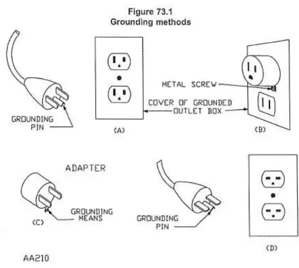
b) For grounded, cord-connected appliances rated less than 15 A and intended for use on a nominal 120 V supply circuit:
This appliance is for use on a nominal 120 V circuit, and has a grounding plug that looks like the plug illustrated in sketch A in Figure 73.1. A temporary adaptor, which looks like the adaptor illustrated in sketches B and C, may be used to connect this plug to a 2-pole receptacle as shown in sketch B if a properly grounded outlet is not available. The temporary adaptor should be used only until a properly grounded outlet can be installed by a qualified electrician. The green colored rigid ear, lug, and the like, extending from the adaptor must be connected to a permanent ground such as a properly grounded outlet box cover. Whenever the adaptor is used, it must be held in place by the metal screw.
c) For grounded, cord-connected appliances other than as mentioned in (b) To reduce the Risk of Electric Shock, this appliance
has a polarized plug. This plug will fit in a polarized outlet only one way. If the plug does not fit fully in the outlet, reverse the plug. If it still does not fit, contact a qualified electrician to install the proper outlet. Do not change the plug in any way
Connecting the unit
Before the unit can be put in to operation Water, Cleaning products and Electricity must be connected to the unit.
Connections
Water:
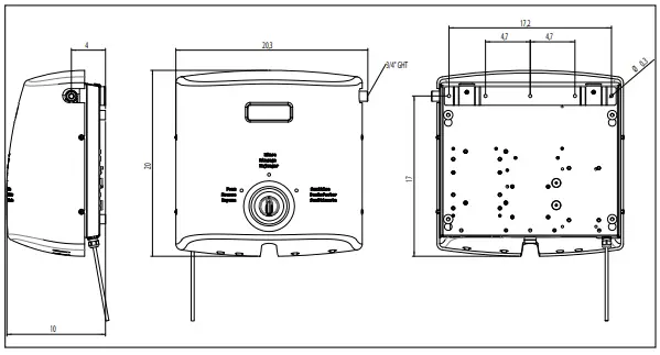
Connect the inlet water hose to the unit, a 3/4″ GHT male connector is required for connection.
Products:
Install pick up hoses on both check valves, connect the pick up hoses to the product cans by using a cap adaptor, use appropriate color-coded cap adaptors.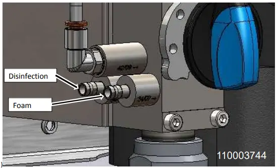
Electricity
| WARNING: ALLWAYS CONNECT ELECTRICITY LAST. |
Connect the plug to the wall socket, make sure the plug is properly connected.
| NOTE: Red LED will illuminate. If not, press red re-set button. |
Preparing the unit
| NOTE: Before use, the unit must be filled with water. |
| NOTE: Make sure the power supply to the unit is not connected. |
Turn on the water supply to the unit.
Open the Ball Value on the outlet hose until no air or dirt comes out. The unit is now ready for use, reconnect the power supply. Bleed the piping system.
Testing the unit
- Make sure water, product and electricity are connected to the unit.
- Pull the outlet to the desired length.
- Connect the desired nozzle foam (white), rinse nozzle (blue) or sanitize(red).
- Connecting the nozzle is done by pulling back the quick connector/ coupler (Fig. 11). Connect the nozzle by pushing the nozzle into opening in the quick connector.
| NOTE: Make sure the nozzle is “clicked” properly in to the coupling, you will hear a small click when the nozzle slips in to place. |
Testing the Rinse function
Hold the ball valve / pistol over sink for testing.
- Turn the selector knob on the unit to rinse position.
- Connect the rinse wand to the ball valve / pistol.
- Open the ball valve / pistol and the pump will start, it may take several seconds for the outlet hose to be filled completely with water.
- The unit is now rinsing.
- Close the ball valve / pistol to stop rinsing. The unit will automatically stop a few seconds after the ball valve / pistol is closed.
Testing the Foam function:
Hold the ball valve / pistol over sink for testing.
- Turn the selector knob on the unit to foam position.
- Connect the foam nozzle to the ball valve / pistol.
- Open the ball valve / pistol. First the pump and then the compressor will start, it will take about 10-15 seconds for the outlet hose to be filled completely with foam.
- The unit is now foaming.
- Close the ball valve / pistol to stop foaming, the unit will automatically stop, it can take up to 10 – 20 seconds after the ball valve / pistol is closed before the unit stops.
- We recommend maximum 20 min. continuous operation of the compressor (foam mode).
| WARNING: When opening the ball valve / pistol after unit has stopped in Foam position, a burst of Foam/Air/Water will come out. This as the outlet hose is filled with foam. The burst will disappear after 3-5 seconds, point the ball valve towards the floor when opening. |
Testing the Sanitise function
Hold the ball valve / pistol over sink for testing.
- Turn the selector knob on the unit to sanitise position.
- Connect the blue sanitise nozzle to the ball valve / pistol.
- Open the ball valve / pistol and the pump will start, it may take several seconds for the outlet hose to be filled completely with sanitiser.
- The unit is now sanitising.
- Close the ball valve / pistol to stop sanitizing, the unit will automatically stop a few seconds after the Bball valve / pistol is closed.
If all 3 tests perform correctly the unit is ready for use.
Checking the unit for leaks
- Remove the cover by loosening the 4 screws on both side of the unit using a 4mm Allen key.
- Check all connections and hoses for leaks.
- Once you have determined that there are no leaks mount the cover again, tighten the 4 screws.
Service/Maintenance instructions
| WARNING: Service/Maintenance may only be carried out by authorized and qualified personnel. |
Recycling and scrapping
Recycle the wrapping and scrap the unit according to recommendations from the local authorities.
Descaling
The following descaling internals must be observed to prevent lime build up in the unit, that can discontinue operation of the unit
| °dH | ppm | Time between Descaling |
| 0-5 | 18-90 | 12 months |
| 5-10 | 90-180 | 6 to 12 months |
| 10-15 | 180-270 | 3 to 6 months |
| 15-20 | 270-360 | 3 to 6 months |
| >20 | >360 | 1 to 3 months |
Troubleshooting
For details regarding troubleshooting see troubleshooting guide.
| WARNING: Service/Maintenance may only be carried out by authorized and qualified personnel. |
Specifications
| Technical Data | ||
| Water | Units | 110Vac 60 Hz version |
| Max.Outlet pressure. | PSI – MPa (Bar) | 124 – 0,85 (8,5) |
| Comsumption during rinsing. | Gal/min. – L/min. | 3-11 |
| Consumption during foaming. | Gal/min. – L/min. | 1.3 – 5 |
| Min. pressure. | PSI – MPa | 29 @5gal/min – 0,2@20 l/min |
| Max. pressure. | PSI – MPa | 72 – 0,5 |
| Max. water temp. | °F – °C | 158 / 70 |
| Pipe dimension inlet Ø | inch | 3/4“ GHT |
| Compressed air (build-in compressor) | ||
| Air pressure. | PSI – MPa (Bar) | 72 – 0,5 (5) |
| Compressed air consumption. | Gal./min – NL/ min | 6 – 23 |
| Electricity | ||
| Supply voltage. | V | 1/PE 110 Vac ±10% |
| Frequency. | Hz | 60 Hz ± 2 |
| Motor load (kW) | kW | 1 |
| Nominal current. | A | 11,1 |
| Fuse. | A | 12 |
| L1, L2, L3, PE | mm2 | 1.5 |
| General | ||
| Sound level ISO 11202 | dB | Below 70 |
| IP class | IP | 54 |
| Dimensions H x B x D | in – mm | 19,7 x 19,7 x 10,2 500 x 500 x 260 |
| Weight. | lbs – kg | 66 -30 |
| Max hose length | Ft – m | 82 Ft – 25 m |
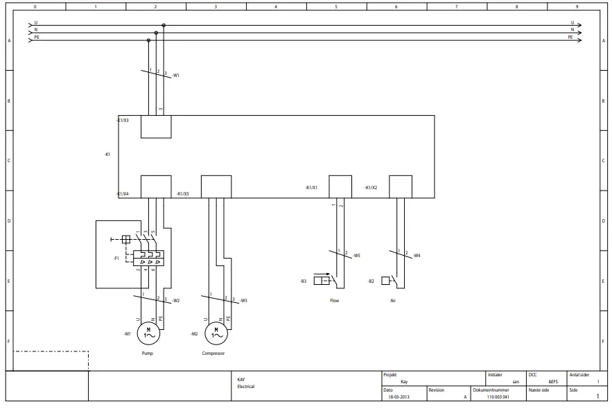
Electric diagram
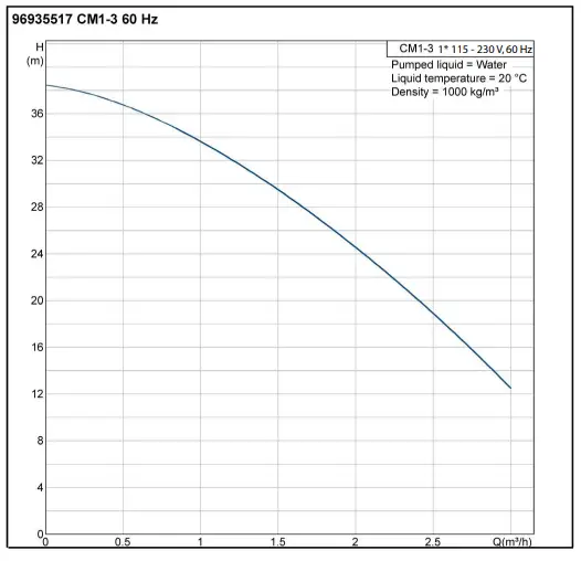
Pumpecurve
Overview
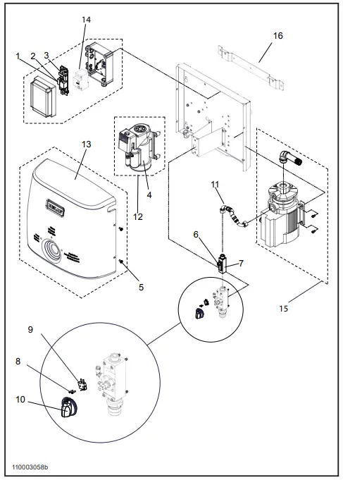
| Pos./Ref. | No. | No. | Description |
| 1 | 110003166 | 83900071 | Fuse 12 A |
| 2 | 110003167 | 83900070 | Fuse 0,315 A |
| 3 | 110002644 | 92214059 | Controller board Carte |
| 4 | 110003159 | 92214026 | Hose Teflon |
| 5 | 110003168 | 88020017 | Screws for Cover Vis |
| 6 | 110003165 | 83050051 | Reed switch for Flow switch |
| 7 | 110002638 | 83050050 | Flow switch |
| 8 | 110003170 | 88020018 | Screws for compressor switch |
| 9 | 110002636 | 83055100 | Compressor switch |
| 10 | 110003156 | 92214011 | Selector knob |
| 11 | 110005172 | 85032013 | SS braided hose |
| 12 | 110002632 | 84550001 | Compressor |
| 13 | 110002630 | 92214058 | Cover |
| 14 | 110002622 | 83000800 | Thermal overload |
| 15 | 110002650 | 8460087 | Pumpe cpl. |
| 16 | 110002629 | 92213793 | Wall bracket Support mural |
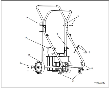
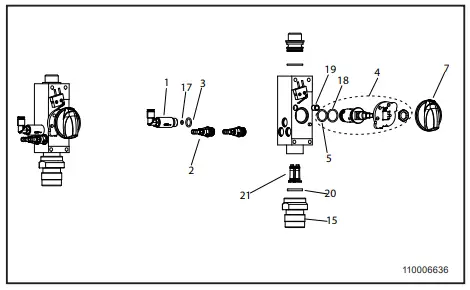
Installation Diagram
| Pos./Ref. | No. | No. | Description |
| 1 | 110003096 | Air Check valve | |
| 2 | 110004434 | Product check valve | |
| 3 | 110005516 (110002952) | O-ring kit | |
| 4 | 110002501 | Selector valve axel | |
| 5 | 110005516 (110002956) | O-ring kit | |
| 6 | 110005516 (110003172) | O-ring kit | |
| 7 | 110003156 | Selector knob | |
| 110002633 | Block cpl. | ||
| 8 | 110003205 | Mounting kit for cart | |
| 9 | 110003204 | Mounting kit for unit on cart | |
| 10 | 110003197 | Mounting kit productholder | |
| 11 | 110003207 | Mounting kit for caster | |
| 12 | 110003206 | Mounting kit for wheels | |
| 13 | 110003177 | Castor cpl. | |
| 14 | 110003176 | Back wheel cpl. | |
| 15 | 110002985 | Coupler | |
| 16 | 110004658 | Bracket for nozzles and cables | |
| 17 | 110005516 (0635021) | O-ring kit | |
| 18 | 110005516 (110002955) | O-ring kit | |
| 19 | 110002392 | Flexible pressure piece | |
| 20 | 110005516 (110002961) | O-ring kit | |
| 21 | 110004219 | Injector kit | |
Customer Support
ECOLAB
KAY CHEMICAL COMPANY
8300 Capital Drive
Greensboro, NC. 27409
USA
(800) 529-5458


