
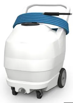
FOAMit FI-50N-SM 50 Gallon Smart Foam Unit
READ ALL INSTRUCTIONS BEFORE OPERATING EQUIPMENT
WARNING

Read this manual completely and understand the machine before operating or servicing it.
- Read all instructions before installing or operating unit.
- Always wear appropriate personal protective equipment (PPE) when operating or servicing unit.
- Always follow all chemical safety precautions and handling instructions provided by the chemical manufacturer and Safety Data Sheet (SDS).
- If this unit is modified or serviced with parts not listed in this manual, the unit may not operate correctly.
- Never point the discharge wand at yourself, another person, or any object you do not want covered in chemical.
- Always keep the air trigger port clean and free of blockages or debris. If the port becomes dirty or blocked, disconnect the compressed air source from the unit immediately and clean out the port before proceeding.
- Always keep the discharge hose free of kinks or obstructions.
- Always rinse and drain unit after use (as described in the After Use Instructions). Always store unit disconnected from the compressed air source.
- Do not exceed an incoming air pressure of 100 psi (7 bar).
- Do not exceed a fluid temperature of 100˚F (37˚C).
- Always flush the unit with fresh water for 5 minutes when switching from an alkaline to an acid or an acid to an alkaline.
- Only use clean and dry air. Air must be filtered and free of moisture or pump life will be diminished. If needed, install a water separator (WS-20CFM) before the unit.
- Do not use an air lubricator before the unit.
PROTECT THE ENVIRONMENT
Please dispose of packaging materials, old machine components, and hazardous fluids in an environmentally safe way according to local waste disposal regulations.
Always remember to recycle.
*Specifications and parts are subject to change without notice.
| REQUIREMENTS | |
| Compressed air requirements | 40-80 psi (3-5 bar) with 5-10 cfm (141-283 l/min) |
| Liquid temperature range | 40-100˚F (4.4-37˚C) |
| Chemical compatibility | Chemical products used with this equipment must be formulated for this type of application and compatible with unit materials and pump seals. For more information on chemical compatibility, consult the manufacturer or SDS for your product or contact our customer service department. |
| SPECIFICATIONS | |
| Power type | Compressed air |
| Chemical pickup type | Draws from pre-mixed solution |
| Number of products unit can draw from | One product |
| Capacity | 50 gallons (189.27 liters) |
| Discharge hose diameter/length | 30 ft. (9.1 m) bonded hose, with 5/8 in. (15.9 mm) and 1/4 in. (6.4 mm) inside diameter |
| Discharge wand/tip type | Ultra high molecular weight (UHMW) polyethylene handle and wand extension, with 65 fan tip and built-in zero tip |
| Output distance | With zero tip: 17-21 ft. (5.2 m – 6.4 m) With fan tip (ST65150): 16-20 ft. (4.9 m – 6.1 m) |
| Output volume | With zero tip: 20-32 gal/min (75-121 l/min) of foam With fan tip (ST65150): 20-32 gal/min (75-121 l/min) of foam |
| Flow rate* | 2 gal/min (7.6 l/min) |
| Pump seals | Santoprene, Viton, or Kalrez |
| Wheel type | Two 10 inch non-marking wheels, two 5 inch casters with lock |
*Dilution rates and flow rates given are based on chemical with viscosity of water and factory air pressure settings.
Operation Instructions
- Verify that the drain plug (DP-A) is securely closed.
- Follow all instructions from the chemical manufacturer. Fill the tank with water and the advised percentage of chemical concentrate.
- Verify that the valve (PVCV34FM) at the base of the suction line is open, to allow fluid into the suction line.
- Verify that the air trigger port is clean and free of blockages or debris, and the discharge hose is not kinked or obstructed.
- With the wand pointed in a safe direction, connect an air line to the air inlet fitting (AP25).
Note: When you connect the air line, listen for any sound from the unit. If you hear the pump activate and begin to cycle, disconnect the air line immediately. This indicates that there is a blockage or other problem somewhere
in the system, which could cause the unit to activate spontaneously. The problem must be addressed before proceeding (see “Troubleshooting Instructions”). - Place thumb over the air trigger to activate the unit and begin foaming.
- While the unit is running and discharging product, adjust the needle valve (NV14Y) as needed to regulate the wetness or dryness of the foam following the steps below:
- Close needle valve completely in clockwise direction.
- Open needle valve in counter-clockwise direction 2 complete turns.
- Continue to open needle valve in ¼ turn increments, allowing 30 seconds between adjustments, until desired consistency of foam is achieved.
- Release the air trigger to stop foaming.
Note: When you release the air trigger, the unit will shut off and depressurize. Foam that is already in the discharge hose may seep out, but no more foam will be created until you cover the air trigger again.
After Use Instructions
- Open the drain plug (DP-A) and drain the unit tank.
- Rinse the unit tank thoroughly with fresh water. Then replace the drain plug and fill the tank with fresh water.
- Activate the unit and allow it to run for 2-4 minutes, or until all chemical has been flushed from the system.
- Open the drain plug (DP-A) and drain any water remaining in the unit tank. Then replace and secure the drain plug.
- Disconnect the air line from the air fitting (AP25).
- Allow any liquid remaining in the discharge hose to drain out through the discharge wand before storing the unit.
Maintenance Instructions
To keep your unit operating properly, periodically perform the following maintenance procedures:
Note: Before performing any maintenance, ensure that the unit has been disconnected from the air supply according to the “After Use Instructions.” Also ensure that the unit tank is empty, and/or close the valve (PVCV34FM) at the base of the suction line to shut off the flow of liquid from the tank. Reopen the valve after maintenance is complete.
- Inspect the air pump (P56/P56K/P56V) for wear and leaks.
- Inspect all hoses for leaks or excessive wear. Make
sure all hose clamps are in good condition and properly secured. - Check the air trigger port on the handle for debris and clean as needed. When cleaning, be careful not to push debris into the port, as it may become lodged inside and create a blockage.
- Clean and replace the filter (AFR25) located within the air regulator (R25) as needed. Access the filter by unthreading the air regulator bowl (ABR25) from the air regulator (R25).
- Check the suction line and strainer (STR38-IL) for debris or blockages, and clean as needed.
- Drain your air compressor tank on a regular basis to help extend pump life. An air source with a high moisture content will accelerate pump wear. Note: If your air source has a high moisture content, you may wish to install a water separator (WS-20CFM) before the unit.
Troubleshooting Instructions
- Check to ensure that the discharge hose is uncoiled properly, and that there are no kinks that could obstruct fluid flow.
- Check the suction line and strainer for debris or damage. Clean or replace as needed. To prevent damage to the unit, the strainer (STR38-IL) must always be used.
- If the pump is cycling but will not pull product, and the suction line is clear, make sure the valve (PVCV34FM) at the base of the suction line is open.
- Check the air regulator bowl (ABR25) and air filter (AFR25) for debris such as water, oil, or rust particles. Clean by unthreading the air regulator bowl (ABR25) from the air regulator (R25).
- If the needle valve (NV14Y) is open too far, the pump (P56/P56K/P56V) may cycle improperly due to lack of air pressure. If this occurs, close and readjust the needle valve (NV14Y) as described in the Operation Instructions.
- Make sure proper foaming chemical and concentration are being used.
- If air passes through the pump (P56/P56K/P56V) without cycling, the pump needs to be replaced.
- If solution backs up into the air regulator bowl (ABR25), the check valve (CV38) needs to be replaced.
- If foam comes out wet, no matter where the needle valve (NV14Y) is positioned, the check valve (CV38) may need to be replaced.
- Check for proper air pressure on the air gauge (AG100). The air regulator (R25) is factory set at 50 psi (3.4 bar). Operating range is 40 to 80 psi (3 to 5 bar) with 5 to 10 CFM (141.6 to 283.3 l/min).
- If the unit operates at a reduced pressure:
- Check the air compressor supplying the unit. If the pressure is less than 40 psi, turn the unit off until the compressor can catch up.
- If the air supply is 50 psi (3.4 bar) or above, check the air gauge (AG100), which should read near 50 psi (3.4 bar). If the air gauge reads more or less than 50 psi (3.4 bar), adjust the pressure by turning the knob on the top of the air regulator (R25).
- If the problem persists, the stainless steel mixing mesh (SS-MESH) inside the tee fitting (SST12HB38) could be plugged. Remove and clean the mesh following the instructions below:
- Ensure that the unit has been flushed and disconnected from the air supply according to the “After Use Instructions.” Also ensure that the unit tank is empty, and/or that the valve (PVCV34FM) at the base of the suction line is closed.
- Remove the stainless hose barb (HBSS1258) from the tee fitting (SST12HB38).
- The stainless steel mixing mesh (SS-MESH) is located inside the tee fitting (SST12HB38). Remove the old mesh and the screen that holds it in place. If the mesh and screen are in good condition, they can be cleaned and re-used. If not, they should be replaced with new parts.
- Insert the new mesh (SS-MESH).
- Insert the new screen (SSST). Make sure it is seated securely, but not bent or deformed.
- Reconnect the hose barb (HBSS1258) to the tee fitting (SST12HB38). Attach the 5/8 inch hose to the hose barb (HBSS1258) and secure it with the screw band clamp (SSC58).
- If you found a lot of particles or blockages inside the mesh, check the suction line strainer (STR38-IL) to make sure it is in place and operating correctly.
- If the unit activates when the air trigger port is not covered:
- Verify that the air trigger port is clean and free of blockages or debris, and the discharge hose is not kinked or obstructed.
- If the problem persists, try bypassing the air trigger. To do this, disconnect the 1/4 inch hose from
the wand. Point the wand in a safe direction and connect an air line to the unit. Then, use your thumb or finger to seal the open port of the 1/4 inch hose at the wand.- If the unit activates when you connect the air line, the valve block (SM-PV) may need to be replaced.
- If the unit does not activate when you connect the air line, the hose or wand assembly may need to be replaced.
- If the unit does not activate when the air trigger port is covered:
- Confirm the incoming air supply is consistently 50 psi (3.4 bar) on the air guage (AG100).
- If the problem persists, the valve block (SM-PV) may need to be replaced.
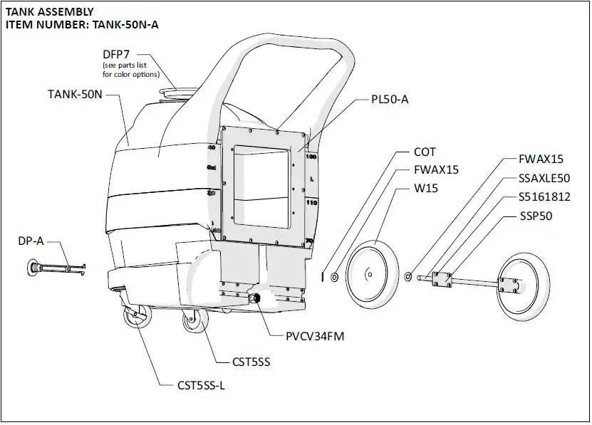
TANK ASSEMBLY ITEM NUMBER: TANK-50N-A

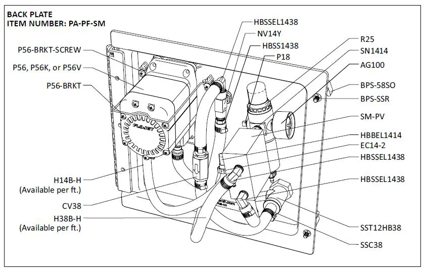
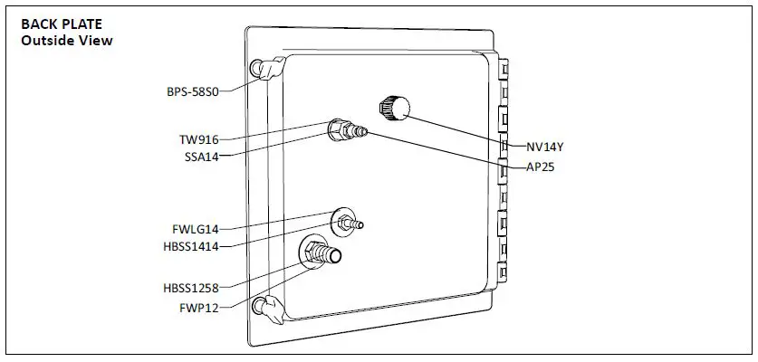
BACK PLATE ITEM NUMBER: PA-PF-SM

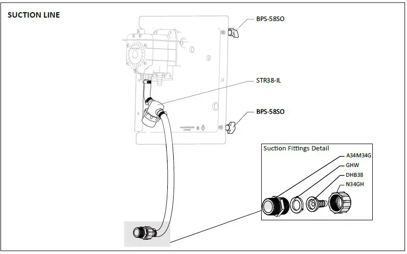
SUCTION LINE
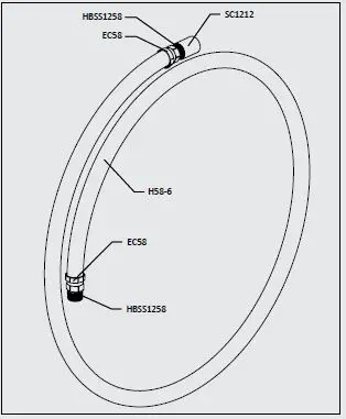
OPTIONAL HOSE ATTACHMENT (INCLUDED) ITEM NUMBER: SM-EA
Installation Instructions
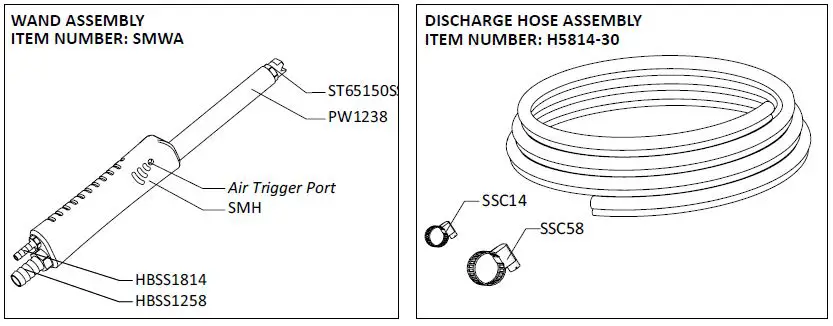
- Remove wand (PW1238) from handle (SMH)
- Thread HBSS1258 from hose attachment into handle (SMH)
- Thread wand (PW1238) onto coupler (SC1212) at the end of hose attachment.
ITEM NUMBER EC58 OETIKER CLAMP 0.625 ID H58-6 6 FT. OF 5/8 INCH BLUE HOSE HBSS1258 STAINLESS STEEL HOSE BARB 1/2 MPT BY 5/8 INCH BARB SC1212 S.S. COUPLER 1/2in BY 1/2in 
READ ALL INSTRUCTIONS BEFORE OPERATING EQUIPMENT
| ITEM NUMBER | DESCRIPTION |
| A34M34G | 3/4 GHT X 3/4 MPT ADAPTOR |
| AG100 | 1.5 INCH DRY MODEL 20 DUAL SCALE GAUGE |
| AKSS34-P | SS ANTI-KINK SPRING FOR 3/4 INCH HOSE |
| AP25 | PLUG 1/4 NPTM AIR FITTING – BRASS |
| B103234 | 10-32 X 3/4 PHIL TRUSS MACH SCR 18-8 |
| B8X58 | 8-15 x 1/2 FLAT PHIL TY-A 18-8 PLN |
| BPS-58SO | Back Panel Screw – 5/8 inch with Stand Off |
| BPS-SSR | 1/4 INCH PUSHNUT BOLT RETAINER STAINLESS STEEL |
| COT | 1/8 X 1 COTTER PIN 18-8 S/S |
| CST5SS | 5in S.S. SWIVEL CASTER WITH 4 IN WHEEL |
| CST5SS-L | 5in S.S. SWIVEL CASTER WITH 4 IN WHEEL AND LOCK |
| CV38 | PVC CHECK VALVE 3/8 BARBS – SS SPRING |
| DFP7 | 7 INCH HINGED CAP ASSEMBLY – INCLUDES BLACK CAP, LID FLANGE AND HINGE PIN |
| DFP7-C | 7 INCH FILL CAP POLYETHYLENE BLACK |
| DFP7-F | 7 INCH TANK LID FLANGE POLYETHYLENE |
| DFP7-PIN | HINGE PIN FOR 7 INCH FILL CAP AND FLANGE |
| DFP7-C-BL | 7 INCH FILL CAP POLYETHYLENE BLUE PANTONE |
| DFP7-C-GN | 7 INCH FILL CAP POLYPRO GREEN PANTONE |
| DFP7-C-RD | 7 INCH FILL CAP POLYPRO RED PANTONE |
| DFP7-C-YL | 7 INCH FILL CAP POLYPRO YELLOW PANTONE |
| DHB38 | 3/4 FLAT SEAT 3/8 HOSE BARB |
| DP-A | DRAIN PLUG ASSEMBLY INCLUDES DRAIN PLUG & GASKET |
| DP | FRONT DRAIN PLUG FOR PORTABLE UNIT POLYPRO |
| DP-G | FKM LATHE CUT 60 DUROMETER FKM |
| EC14-2 | OETIKER CLAMP 13.8 |
| EC58 | OETIKER CLAMP 0.625 ID |
| FWAX15 | FLAT AXLE WASHER |
| FWP12 | 7/8 ID X 1.5 OD X 0.05 THK SSFW |
| FWP14 | C-816 1/2in SS WASHER |
| GHW | GARDEN HOSE WASHER – D-#102 |
| H14B-H | 1/4 INCH BLUE HOSE – Available per ft. |
| H38B-H | 3/8 INCH BLUE HOSE – Available per ft. |
| H5814 | BONDED HOSE 5/8in ID – 1/4in ID |
| H58-6 | 6 FT. OF 5/8 INCH BLUE HOSE |
| HBBEL1414 | 1/4 MPT X 1/4 HOSE BARB BRASS 90 DEG |
| HBSS1258 | STAINLESS STEEL HOSE BARB 1/2 MPT BY 5/8 INCH BARB |
| HBSS1414 | HOSE BARB STAINLESS STEEL 1/4 MPT X 1/4 BARB |
| HBSS1438 | STAINLESS HOSE BARB 1/4 MPT X 3/8 BARB |
| HBSS1814 | 1/8 MPT X 1/4 STAINLESS HOSE BARB |
| HBSSEL1438 | STAINLESS HOSE BARB ELBOW 1/4 INCH NPT X 3/8 HOSE BARB |
| KI1420 | KNOCK INSERT 1/4 -20X11M TS INSERT NUT |
| N34GH | 3/4 GARD HSE SWIVEL NUT |
| NV14Y | FLOW CONTROL VALVE – INCLUDES BLACK KNOB |
| NV14Y-HNDL | BLACK KNOB FOR NEEDLE VALVE – 2839-1/4 |
| P18 | PLUG 1/8 MPT HEX HEAD 304 SS |
| P56 | PUMP WITH SANTOPRENE SEALS – INCLUDES HOSE BARBS, AIR FITTING, AND EXHAUST BARB |
| P56K | PUMP WITH KALREZ SEALS – INCLUDES HOSE BARBS, AIR FITTING, AND EXHAUST BARB |
| P56V | PUMP WITH VITON SEALS – INCLUDES HOSE BARBS, AIR FITTING, AND EXHAUST BARB |
| P56-BRKT | PUMP BRACKET- STAINLESS STEEL |
| P56-BRKT-SCREW | HI LO SCREW FOR RETAINING P56-BRKT |
| PL50-A | FI-50 ADAPTOR PLATE |
| PLPF | PORTABLE FOAMER BACK PLATE W/ HINGE AND HOLES |
| PLPF-PIN | 302 STAINLESS PORTABLE PLATE HINGE PIN |
| PVCV34FM | PVC VALVE 3/4in FPT X 3/4in MPT |
| PW1238 | POLY WAND – 1/2 MPT X 3/8 FPT – UHMW |
| R25 | AIR REGULATOR – 1/4fpt TWO PORT 1/8fpt TWO PORT – INCLUDES FILTER AND BOWL |
| ABR25 | METAL AIR BOWL for R25 |
| AFR25 | AIR FILTER for R25 |
| S142034 | 1/4-20 X 3/4 PHIL TRUSS M/S 18-8 |
| S5161812 | 5/16-18 x 1/2 Phil Pan 18-8 |
| SC1212 | S.S. COUPLER 1/2in BY 1/2in |
| SM-PV | PNEUMATIC VALVE FOR SMART TECHNOLOGY UNITS |
| SMH | HANDLE FOR BONDED HOSE – 1/2in FPT AND 1/8in FPT – UHMW |
| SN1414 | STAINLESS 1/4MPT X 1/4MPT NIPPLE |
| SSA14 | SS304 MALE/FEMALE ADAPTOR 1/4 NPT X 1/4 NPT |
| SSAXLE50 | SSAXLE – 50 GAL 5/8 x 23.05 |
| SSC14 | WORM GEAR CLAMP, SS 1/4IN |
| SSC38 | WORM GEAR CLAMP, S/S (.25-.63) |
| SSC58 | WORM GEAR CLAMP, SS 5/8IN |
| SSP50 | STAINLESS STEEL AXLE PLATE (50 GAL) |
| SSP50-CSTR | STAINLESS STEEL PLATE FOR CASTER SUPPORT |
| SST12HB38 | STAINLESS TEE COMBO 1/2in FPT X 3/8 in BARB WITH SSST AND S.S. MESH |
| SS-MESH | STAINLESS STEEL MESH WITH SSST FOR REPLACEMENT |
| SSST | SCREEN DISC .687 DIA. 10 X 10 MESH @ .020 DIA. 300 SERIES S.S. |
| ST65150 | VEEJET NOZZLE 65150 – 3/8 MPT |
| STR38-IL | IN LINE STRAINER 3/8 BARB 20 MESH 304 STAINLESS EDPM GSKT |
| TANK-50N | 50 GALLON PORTABLE UNIT NATURAL IN COLOR |
| TW916 | 1/2 INT TOOTH L/W 410SS |
| W15 | NONMARKING WHEEL FOR PORTABLE UNITS |
NOTE: All products covered by this patent made for you under any license, should be marked with the notice “U.S.
Patent No. 10,076,760”
20221110 Model No.: FI-50N-SM, FI-50NK-SM, FI-50NV


