![]() Mars M1 Wireless Transceiving Monitor
Mars M1 Wireless Transceiving Monitor
User Manual
Introduction
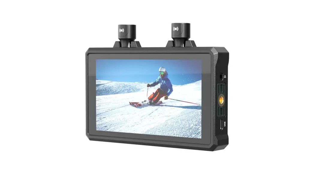
Thank you for purchasing Hollyland Mars M 1 Wireless Transceiving Monitor.
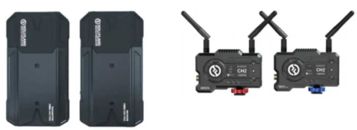
This wireless transceiving monitor system adopts the latest image encoding and decoding technology supporting 5G frequency band transmission. It can work either at the transmitting or receiving end, rendering a unique long-range and low-latency video monitoring experience This User Manual will guide you through the installation and use of the equipment.
Packing List
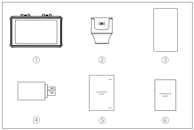
Packing List
| 1 | Monitor | X1 |
| 2 | Lollipop Stubby Antenna | X.2 |
| 3 | Tempered Glass Film | X1 |
| 4 | OTG Adapter | X1 |
| 5 | User Manual | X1 |
| 6 | Warranty Card | X1 |
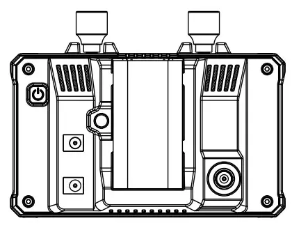
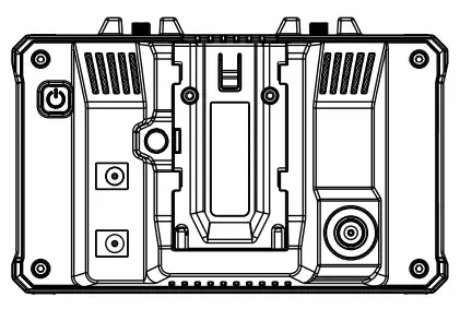
Product Interfaces
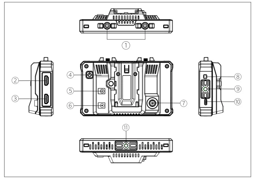
| 1 | RP-SMA Antenna Male Connector | 7 | SDI Input |
| 2 | HDMI Input | 8 | 3.5mm Headphone Jack |
| 3 | HDMI Output/Loop out | 9 | 1/4 Threaded Hole |
| 4 | Power Button | 10 | USB Type-C Port |
| 5 | DC Output (supply power to an external device) | 11 | 1/4 Threaded Hole |
| 6 | DC Input (power supply to the monitor) |
Quick Guide
Power On
Step 1: Install the F970 battery or connect to the DC power supply
Step 2: Press and hold the power button for 3 seconds to turn on the device
Setting up as Transmitting Monitor
Step 1: Connect the device to the video source via the SDI or HDMI interface, wait for the screen to display normally
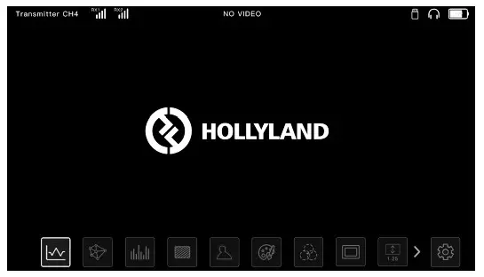
Step 2: Tap on the icon on the lower right corner of the screen to enter the settings menu.
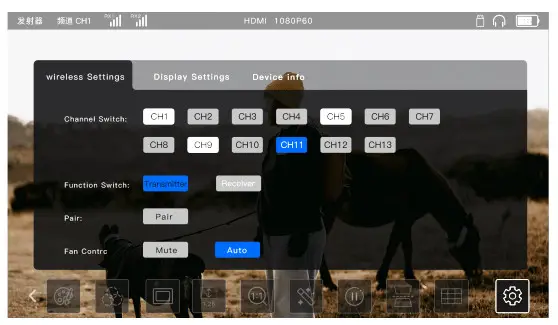
Step 3: Tap Pair to start pairing with the receiver end; the system is compatible with any Hollyland Mars series receiver device.
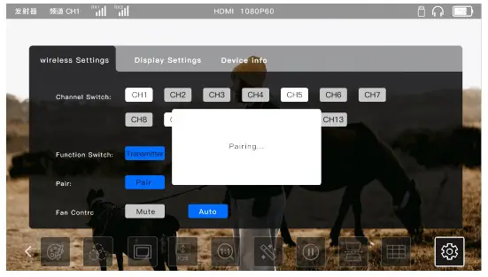
Step 4: The receiver will indicate that the connection is successful when the pairing completes. After proper setup, both the Mars M1 monitor and the receiver end will be able to display the video source image.
Setting up as Receiving Monitor
![]()
Step 1: Tap Pair on the settings menu to start pairing with the transmitter end, which can be any Hollyland Mars series transmitter device.
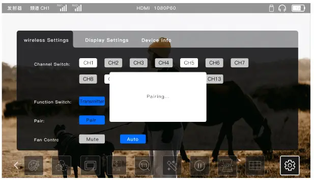
Step 2: When the pairing completes, and if the transmitter end has a video source input, the Mars M1 monitor as the receiving end will display the received image normally.
Unlock/Lock Screen
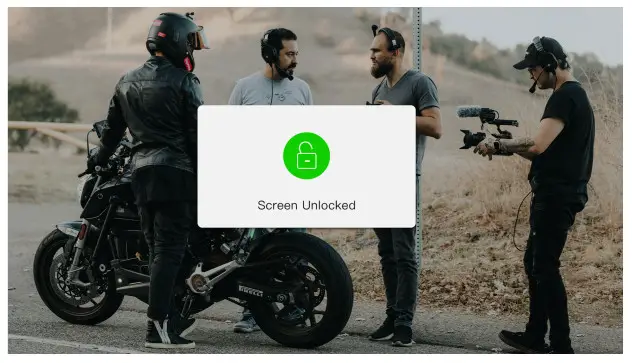
Unlock screen Click the Power Button to unlock the device when it’s in the locked state.
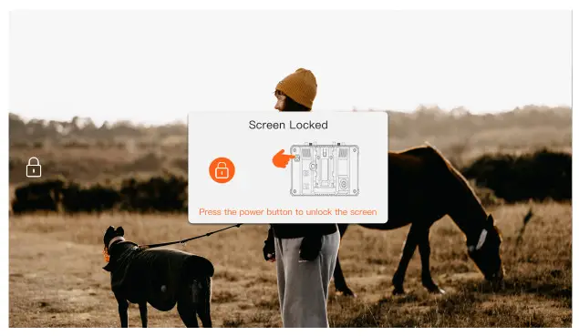
Lock screen: When the device is powered up, click the Power Button to lock the screen
Settings
Frequency Setting Tap to select the channel number in the frequency list to change the connection frequency for the device. Note: Some mobile devices do not support WiFi connection under CH3-CH1 0 frequency. Please switch to other frequencies for WiFi connection.
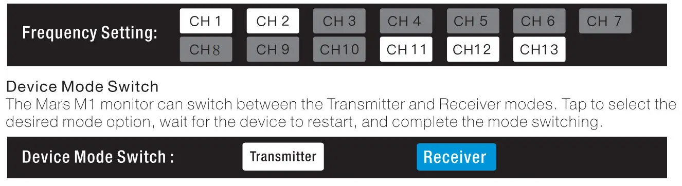
Pairing
After the device is powered on and the screen displays the frequency point number, it’s ready to operate the pairing. One-to-one pairing: Press the pairing buttons of both the transmitter and receiver at the same time to activate pairing. One-to-two pairing: After the transmitter is paired with receiver 1, the transmitter is then paired with receiver 2. The transmitter cannot be paired with two receivers at the same time. Note: Compatible with Mars 300 Pro and Mars 400s Pro
Firmware Upgrade
- Copy the reward upgrade e to a0$8 0ik.
- Turon the 0orioe, attach the USB is with the 0TG Adaptor, ad connect the latter to tho Mars M monitor via the US8 y0er-G port.%
- Wat forth8 y$tom to enter the $y$tor up9rad interface au0atic.ally,
- After the upgrade is complete, wait for the device tore. start automatically to complete the Upgrade
Note. Fleas ensure an st.a0e power $up0/y luring the upgrade process to avoid power failure
APP Operations
APP installation and Monitoring on i0S and Android Systems
- Search for the Hollyview APP on APP Store or Google Play, and download and install the APP on the mobile device.
- Pairing with auto-scan: Launch the APP and start auto-scanning to pair up with the Mars M1 monitor. Once paired, the APP screen will display the video image from the monitor.
- Pairing with manual ID input: Launch the APP and manually enter the device ID number to pair up. Once paired, the APP screen will display the video image from the monitor.
LUT Settings
Tap the LUT icon in the main menu at the bottom of the Mars M1 main screen to open the LUT settings menu and perform the following operations:
Import LUT
- Put the LUT files in a USB disk formatted as FAT32, and attach it to the OTG adapter connecting to the Mars M1 monitor via the USB Type-C port.
- Tap the LUT icon in the main menu, select the Import LUT option from the settings menu, and wait for the system to retrieve and import the LUT files from the USB disk.
Note: The suffix of the LUT file must be .cube, and the file name cannot exceed 128 characters - Tap select a file for import, then tap the desired position from the F1, F2, F3, F4, or F5 buttons in the menu to locate the file.
- Tap Import LUT” to import the corresponding LUT file to the corresponding button option.
RGB and BGR Color Charts: The system’s default option is the RGB color chart.
Tap on the toggle icon in the menu to switch to the BGR color chart.
LUT Application:
Tap the LUT icon in the main menu activates the function. The LUT file on the F 1 button will be applied by default.
Tap to select the corresponding LUT file on the F2, F3, F4, or F5 button to change Tap the selected F1F5 button again to deselect the corresponding LUT file Tap on the LUT icon or elsewhere on the screen to close the LUT settings menu.
Check LUT File Name: After the selected LUT file is applied, the corresponding LUT file name will be displayed on the top info bar.
Note: The five camera LUT files by factory default are as follows:
F1: Canon_CO-Log.cube
F2: Canon_C-Log2.cube
F3 Sony_S-Log.cube
F4 Sony_SL0g2.cube
F5 Slog3to709TypeA.cube
Parameter
| Transmitter Mode | Receiver Mode | |
| Video Input Interface | SDI input (BNC female) FIDMI input (Type-A female) | |
| Video Output Interface | HDMI output (Type-A female) | HDMI output (Type-A female) |
| Antenna Interface | Two RP-SMA male interfaces | Two RP-SMA male interfaces |
| Power Input Interface | DC power input | DC power input |
| Power Output Interface | DC power output | DC power output |
| Headphone Jack | 3.5mm jack | 3.5mm jack |
| Firmware Upgrade Interface | USB Type-C | USB Type-C |
| Screen Size | 5.5″ touchscreen | 5.5″ touchscreen |
| Screen Resolution | 1920×1080 pixels | 1920×1080 pixels |
| Pixel Density | 403PPI | 403PPI |
| Aspect Ratio | 16:09 | 16:09 |
| Brightness | 1000nits | 1000nits |
| Contrast Ratio | 1000:1 | 1000:1 |
| Supply Voltage Range | 7-16V DC, nominal 12V | 7-16V DC, nominal 12V |
| Power Consumption | <14. 5W(without DC output) | <10W(without DC output) |
| Net Weight | 380g excluded) | 380g (antennas excluded) |
| Dimension | (LxWxH) :152x96x40mm (antennas excluded) | (LxWxH) :152x96x40mm (antennas excluded) |
| HDMI: | / | |
| 720P50/59.94/60 Hz | / | |
| 1080150/59.94/60 Hz | / | |
| 1080P23.98/24/25/29.97/30/50 | / | |
| /59.94/60 Hz | ||
| 3840x2160P23.98/24/25/29.97/ | / | |
| 30 Hz | ||
| Input Video Formats | 4096x2160P23.98/24/25/29.97/ | |
| 30 Hz | ||
| SDI: | ||
| 7201%0/59.94/60 Hz | / | |
| 1080150/59.94/60 Hz | / | |
| 10801’323.98/24/25/29.97/30/50 | / | |
| /59.94/60 Hz | ||
| HDIvIl in HDMI out: | HDMI out: | |
| 120P50/59.94/60 Hz | 720P50/59.94/60 Hz | |
| 1080150/59.94/60 Hz | 1080150/59.94/60Flz | |
| 1080P23.98/24/25/29.97/30/50 | 1080P23.98/24/25/29.97/30/ | |
| /59.94/60 Hz | 50/59.94/60 Hz | |
| Output Video Formats | 3840x2160P23.98/24/25/29.97/ | 1080P50/59.94/60 |
| 30 Hz | ||
| 4096x2160P23.98/24/25/29.97/ | 1080P50/59.94/60 | |
| 30 Hz | ||
| SDI in HDMI out: | ||
| 720P50/59.94/60 Hz | 720P50/59.94/60 Hz | |
| 1080150/59.94/60 Hz | 1080i50/59.94/60Hz | |
| 1080P23.98/24/25/29.97/30/50/ | 1080P23.98/24/25/29.97/30 | |
| 59.94/60 Hz | /50/59.94/60 Hz | |
| Operating Frequency | 5.1-5.9GHz | 5.1-5.9GHz |
| Codec Technology | H.264 | H.264 |
| Bit Rate | 12Iv1bps | 12tv1Icips |
| Transmit Power | Max. 22dBm | Max. 22dBm |
| Receiver Sensitivity | -80dBm | -80dBm |
| Transmission Delay | <80ms | <80ms |
| Bandwidth | 20MHz | 20MHz |
Note: The frequency band and transmit power varies by country and region
Safety Precautions
Do not place the product near or inside heating devices (including but not limited to microwave ovens, induction cookers, electric ovens, electric heaters, pressure cookers, water heaters, and gas stoves) to prevent the battery from overheating and exploding.
Support
lf you encounter any problems in using the product or need any help, please contact
Hollyland Support Team via the following ways:
If encounter any problems in using the product or need any help, please follow these ways to get more technical support:
![]() Hollyland Products User Group
Hollyland Products User Group![]() HollylandTech
HollylandTech![]() HollylandTech
HollylandTech![]() [email protected]
[email protected]![]() www.hollyland-tech.com
www.hollyland-tech.com
Statement
All copyrights belong to Shenzhen Hollyland Technology Co, .LTD. Without the written approval of Shenzhen Hollyland Technology Co,.LTD, no organization or individual may copy or reproduce part or all of the content of the text without authorization, and may not disseminate it in any form.
Trademark Statement
All trademarks are owned by Shenzhen Hollyland Technology Co, LTD.
Note: Due to product version upgrades or other reasons, this quick guide will be updated from time to time. Unless otherwise agreed, this document is provided as a guide for use only. All representations, information, and recommendations in this document do not constitute warranties of any kind, express or implied.
FCC Requirement
Any changes or modifications not expressly approved by the party responsible for compliance could void the user’s authority to operate the equipment. This device complies with Part 15 of the FCC Rules. Operation is subject to the following two conditions·
- this device may not cause harmful interference.
- this device must accept any interference received, including interference that may cause undesired operation.
FCC Radiation Exposure Statement:
The device has been tested and complies with FCC SARR limits.
Note: This equipment has been tested and found to comply with the limits for a Class B digital device, pursuant to Part 15 of the FCC Rules. These limits are designed to provide reasonable protection against harmful interference in a residential installation.
This equipment generates, uses, and can radiate radio frequency energy, and if not installed and used in accordance with the instructions, may cause harmful interference to radio communications. However, there is no guarantee that interference will not occur in a particular installation. If this equipment does cause harmful interference to radio or television reception, which can be determined by turning the equipment off and on, the user is encouraged to try to correct the interference by one or more of the following measures:
- Reorient or relocate the receiving antenna.
- Increase the separation between the equipment and receiver.
- Connect the equipment to an outlet on a circuit different from that to which the receiver is connected.
- Consult the dealer or an experienced radio/TV technician for help.
![]()


