![]()
Martec C900 FL-TG Wireless Monitor
Information in this document is subject to change without notice. All rights reserved.
Please send comments to:
- E-mail: [email protected]
- Phone: 908.233.0101
- Fax: 908.233.4111
- 1 Revision History
| REV | ECN | Description | Date | By |
| 1.0 | Initial release | 2020/01/20 | CM | |
| 1.01 | Added Channel Frequency Table | 2020/01/28 | CM | |
| 2.0 | 10585 | Added Required FCC information | 2020/08/11 | DJS |
Device Overview
The wireless monitor (also called radio) is a transceiver that monitors the health of a light and wirelessly provide status to a central location. It will also provide the health of a battery backup in light. In an ideal condition, the 915 MHz frequency band (sub 1GHz) signal has a range of up to 4,000 feet. Device has an interface 4 wire assembly harness to power up with 5 Volt / Ground and TTL serial transmit and receive interface data lines. Device can also be adapted to connect to a digital addressable lighting interface (DALI) for network based systems that control lighting applications. A provision application tool is included with the wireless monitor for viewing and setting the device parameters.
Applications
- Internet of Things (IoT)
- Sensor networks
- Metering
- Industrial Automation
- Smart city
Hardware/ Software Needed
- Computer or Tablet (Windows 10 or Higher), not included with product
- Provision Application, included with product
- 6 Feet Custom Cable (USB B to Mini USB), sold separately
Warning
Important device safety and handling information. Follow and comply with site safety policies. RF Frequency Notice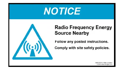
Electrostatic sensitive device
There is an electrostatic sensitive device (ESD) inside equipment. 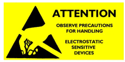 Prior to handling equipment, electrically discharge yourself by momentarily touching an unpainted metal ground object.
Additional Notice
- Terminate device RF port with a 50 Ohm load using antenna.
- Maximum RF input level is 10 dBm at the device RF port.
Installation
Power up wireless monitor with 5 Volts and Ground. With a current capability of at least 250 milli-amps.
Provision Application
- 8880-027_Application_Provision_Tool_CVL
- 8880-029_AutoFirmwareProgramming
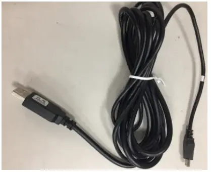
Connect the Computer / Tablet to the wireless monitor using custom cable, shown in pictures below.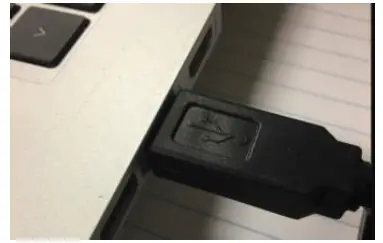
- Tablet with cable (Connection End 1)
- Custom Cable USB-B to Mini-USB

- MGL Light Fixture with cable (Connection End 2)
- Make sure the wireless monitor amber LED turns “On” located (in underside) next to the mini USB connector. The LED will blink the firmware code revision. Run the ApplicationTo open application, click the executable file called “cvprovision.exe” located in the “8880-027_ Application_ Provision_ Tool_ CVL”. Create a shortcut to this application exe file on your desktop. Screen LayoutThe provision application has the 3 tabs.
- Provision Tab: The Provision tab is to provision wireless monitor in which has fields updated by electrician.
- Status Tab: The Status tab is to check the firmware version and to report back problems to engineer.
- Advanced Tab: The Advanced tab is to load firmware upgrade and for a Super User to make changes.
- On the application provision tab, click the > Refresh button. The COM port that the wireless monitor is connected to will appear on the left field. Click the > Connect button.Figure


Connect Button
Application will connect to the wireless monitor and display the MAC Address. Confirm MAC Address is displayed which is unique identifier for every wireless monitor.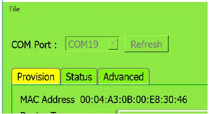
This is the default view of the application Provision tab, shown in figure below.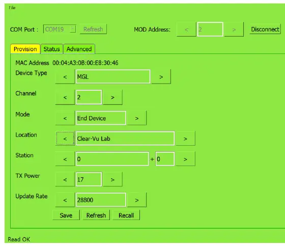
Factory Defaults
The provision tab has the following factory default settings.
| Field | Default Settings | Fields updated at site by Installer | Comment |
| Device Type | MGL | X |
| Channel | 2 | ||
| Mode | End Device | ||
| Location | Your location name | X | |
| Station | 0 + 0 | X | |
| TX Power | 17 | ||
| Update Rate | 28,800 | Unit in seconds 28,800 =8 Hours It can be set as low as 60 seconds. |
User Updates
User shall update the following fields with information from the device assigned location information:
- Device Type
- Station
- Channel
- Location
After any change click the [Save] Button.
In this example: this is the app for a node set as a Station light with station field designator set to “P” “111”.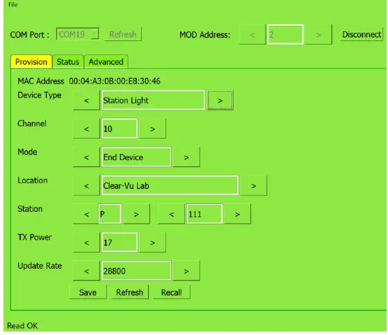
This is the default view of the application Status tab.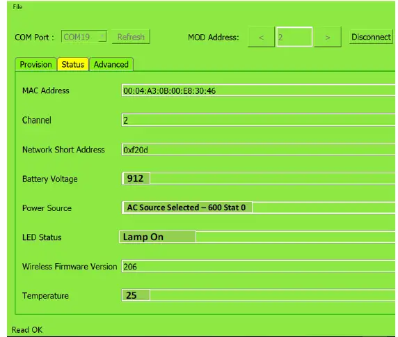
| Field Name | Definition | Comment |
| MAC Address | Unique Identifier | Every unit has a unique value |
| Channel | Radio Frequency Channel | |
| Network Short Address | Use to ping device | |
| Battery Voltage | Internal Battery Charge / Discharge Voltage | |
| Power Source | Which source is powering up light fixture | |
| LED Status | External Luminaire | |
| Wireless firmware version | Active wireless monitor firmware installed. | |
| Temperature | Sensor in underside ambient temperature | Default value in Celsius |
This is the default view of the application Advanced tab.  You must be a Super User to use the Advanced tab.
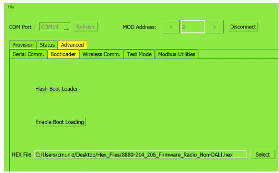 To activate the Super User mode perform the following: Temporarily click the >Disconnect button. On the window top left corner click Settings, checkmark the box next to Super User, click the >Save button. Connect back to the wireless monitor by clicking the > Connect button.ff
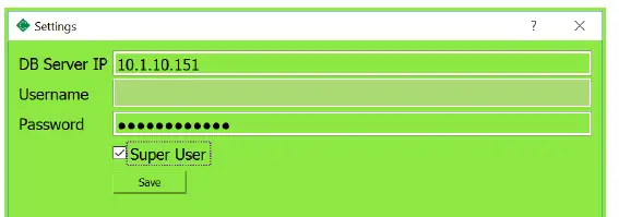 For safety reasons, on the re-opening app, the Super User box has to be check mark and settings re-saved. Load Firmware The next step is generally not required as the wireless monitor comes with the latest firmware code loaded. How to load firmware in radio. Click the > Advanced tab, a warning window will pop up, click > Yes to proceed.
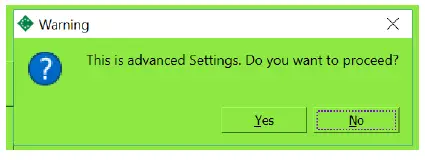 Click the > Bootloader tab.
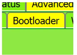 Get the latest hex file(firmware).
 Click the [Select] button. Filename cannot have spaces.Next, click [Flash Boot Loader] button
 Wait while file is uploading. Status bar will pop up.
Status bar will reach 100% and on the bottom left corner it will say Flashing Success. Click the Disconnect and then Connect button. Click the [Status] tab and confirm that the correct firmware version is displayed.Successful firmware upload has been executed. The amber LED will blink the firmware version.
For example: version 206, will blink twice, then pause, then blink six times, and then stay on.
First Time Connection
Click the > File, Click > Fetch Settings.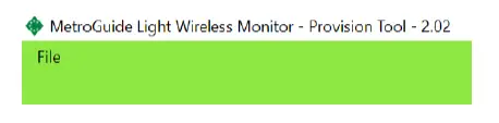 This step is performed once. After each use cover the mini-USB port with cap to protect it from damage.
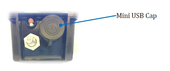
Troubleshooting Guide
The following window will pop up when application is not connected to wireless monitor. Application is ghosted when not connected to a wireless monitor. 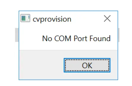 The bottom left corner will state “Not Connected”.
 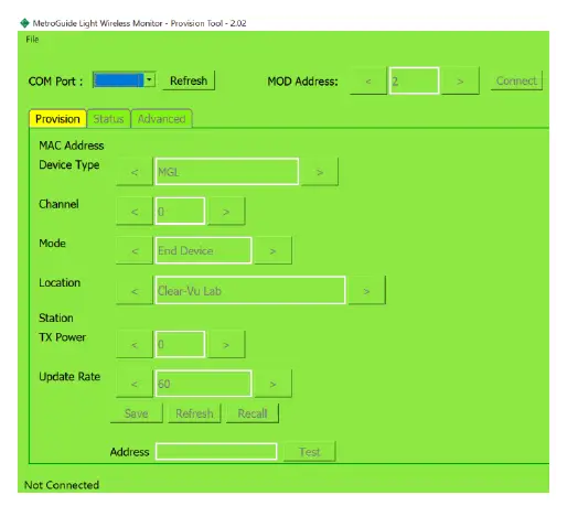 Wireless monitor does not transmitThe update rate is too long. Speed up the update rate by entering a lower value. Be careful as the system configuration will dictate the update rate field value.
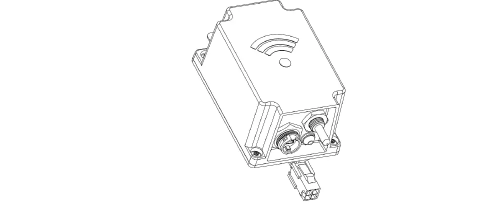
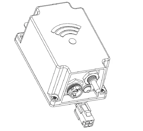
Device Details
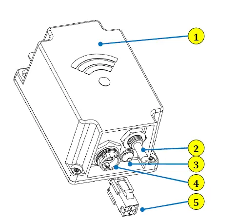
The wireless monitor consist of the following parts:
- Antenna Inside (2in2 )
- Temperature Sensor
- LED (Amber)
- Mini-USB
- Interface Connector
Specification
- Operating Voltage: 5 Volts +/ – 0.25 Volts (250 milli-amps)
- Operating Temperature: -30 °C to 55 °C
RF Specifications
| Frequency band of operation | 902 to 928 MHz |
| Transmit Power | 17 dBm Maximum |
| Frequency RF Channels of operation | See Table 3 |
| Channel | Frequency (MHz) |
| 0 | 903.08 |
| 1 | 905.24 |
| 2 | 907.4 |
| 3 | 909.56 |
| 4 | 911.72 |
| 5 | 913.88 |
| 6 | 916.04 |
| 7 | 918.2 |
| 8 | 920.36 |
| 9 | 922.52 |
| 10 | 924.68 |
| 11 | 926.84 |
| 12 | 915.00 |
RF Frequency Channel Setting
To set the wireless monitor frequency (MHz) signal, click the left or right arrow next to the Channel field located on the Provision tab, click the Save button. For channel and frequency cross-reference, see Table 3 above.Receive Sensitivity: (-) 146 dBm at the pc board RF port.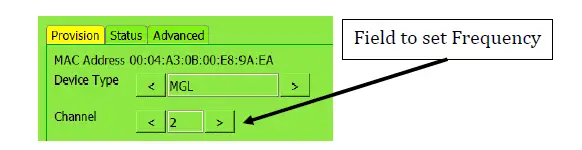
Mechanical
| Dimensions | 2.55 W x 3.89 H x 1.87 L inches Excludes ground tab |
| Approximate Weight | 8 Oz. (226.8 Grams) |
| Power / Communication Interface type | 4 Wires VCC Input (5V), Ground, Transmit, Receive |
Antenna RF Connector type: MMCX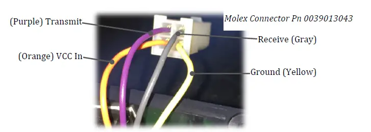
Outline Drawing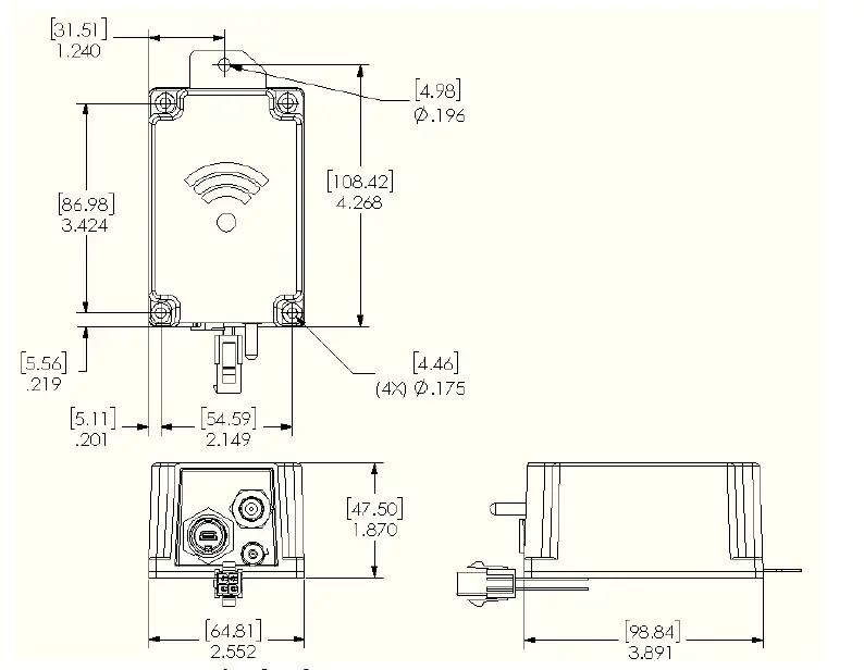
Tools
The following tools are used to install device.
- Tamper-resistant Torx Key T10
- #1 Phillips Screwdriver For pc board installation in housing. The device mounting screws can be change to meet your product overall requirements.
Block Diagram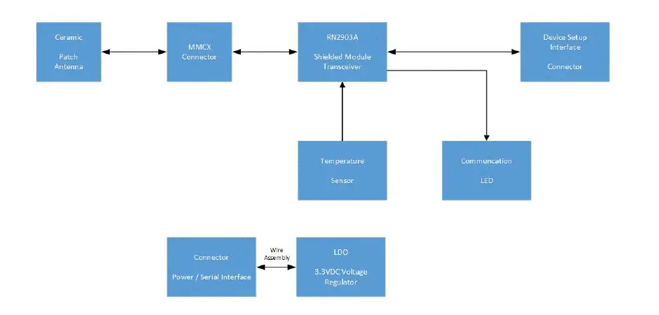
Wireless Monitor The components that make up a wireless monitor are depicted in Figure 26.
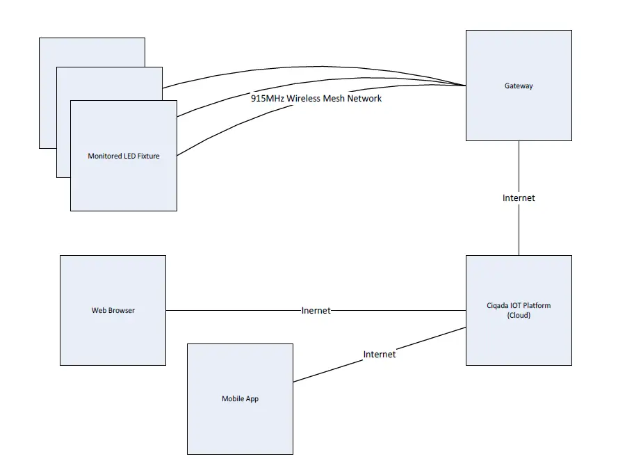
Architecture Overview
A system can consist of the following major component.
- Wireless Monitor

- Gateway
- Ciqada IoT Platform
- Web Browse
- Mobile App
FCC Notice
This device complies with Part 15 of the FCC Rules Operation that is subject to following conditions:
- This device may not cause harmful interference.
- This device must accept any interference received, including interference that may cause undesired operation.Note 1: An FCC ID label must be conspicuously visible on the wireless radio exterior surface.
Note 2: FCC Information to user:Any product changes or modifications not expressly approved by the party responsible for compliance could void the user’s authority to operate the C900 FL-TG.
Note 3: Maximum Permissive Exposure Statement: The C900 FL-TG must be used in a way that a separation distance of at least 20 cm is normally maintained between the transmitter’s radiating structure(s) and the body of the user or nearby persons.
FCC Statement of Information to User
Warranty Information
The wireless monitor has a standard 1 year limited warranty unless otherwise indicated on the shipping package as noted in the purchase agreement.
Warranty Limitations
The warranty is limited to the repair or replacement of the defective product. Mars Int’l will decide which remedy to provide for the defective components as its own discretion. Mars Int’l shall have a reasonable time after determining that a defective product exists to repair or replace the problem unit. The warranty applies to repaired or replaced products for the balance of the applicable period of the original warranty or ninety (90) days from the date of shipment of a repaired or replaced component, whichever is longer. The Mars Int’l standard warranty does not cover products which have been received improperly packaged, altered, or physically damaged. For example, broken warranty seal, labels exhibiting tampering, physically abused enclosure, broken pins on connectors, any alterations made without Mars Int’l authorization, will void all warranty.
Limitation of Damage
The liability for any defective product shall in no event exceed the purchase price for the defective product. Mars Int’l has no liability for general, consequential, incident or special damages.
Limitation of Liability
© Copyright 2020 Mars International. All rights reserved. No part of this publication, or any software included with it may be reproduced. Stored in a retrieval system, or transmitted in any form or by any means, including photocopying, electronic, mechanical, recording or otherwise, without the prior written permission of the copyright holder. Mars International provides this document as is, without any warranty of any kind either expressed or implied including, but not limited to, the implied warranties of merchantability and fitness of a particular purpose. Mars Int’l may makes changes or improvements in the equipment, software or specifications described in this document at any time and without notice. These changes will be incorporated in new releases of this document. This document may contain technical inaccuracies or typographical errors. Mars Int’l waives responsibility for any labor, materials, or costs incurred by any person or party as a result of using this document. Mars Int’l and any of its affiliates shall not be liable for any damages (including, but not limited to, consequential, indirect or incidental, special damages or loss of profits or date) even if they were foreseeable and Mars Int’l has been informed of their potential occurrence, arising out of or in connection with this document or its use.
17 Return Material Authorization (RMA)
No product may be returned directly to Mars Int’l without first getting an approval from Mars. If it is determined that the product may be defective, you will be given an RMA number and instructions in how to return the product. An unauthorized return, i.e., one for which an RMA number has not been issue, will be returned to you at your expense. Authorized returns are to be ship to the address on the RMA in an approved shipping container. It is suggested that the original box and packaging materials should be kept if a defective product needs to be shipped back to Mars. To request an RMA, please call 908.233.0101 and type the extension of the product account manager.
18 Product Identification Scheme
To order wireless monitor or obtain product information use the following table.
| Model | Space | System Topology | Hyphen | Antenna Type | Package |
| C900 | FL | – | TG | ||
| LR | – | TG |
FL= Flood Mesh LR= LoRa


