
FNI ECT-508-105-M IO Link Master IO Link Master Module

Product Information: FNI ECT-508-105-M IO Link Master Module
The FNI ECT-508-105-M IO Link Master Module is a decentralized input and output module designed for connection to an industrial network. It is manufactured by Fuyansheng Electronic (Fujian) Co. LTD and comes with a user manual.
Manual Structure
The manual is organized by organization and the chapters are interconnected. Section 2 covers basic security information, Chapter 3 provides a getting started guide, and Chapter 4 contains technical data.
Typography and Symbols
The manual uses front triangles to represent action descriptions and arrows to show the result of the action. Step programs can also be displayed numerically in parentheses. Decimal numbers are displayed without additional indicators, while hexadecimal numbers are displayed with an additional indicator or with the prefix 0X. Cross-references indicate where to find additional information on a topic. The manual also uses symbols to indicate general comments and important safety notices.
Safety Precautions
Only approved cables should be used with the module. If a defect or equipment failure cannot be corrected, the operation of the equipment must be stopped to prevent damage caused by unauthorized use. Dangerous voltage precautions must be taken and all power sources should be disconnected before using the equipment.
Technical Data
The module has a specific size and mechanical data, as well as operating conditions and electrical data. It also features a network port and function indicator. ECT Node address settings are included in Chapter 4 of the manual.
Product Usage Instructions
To use the FNI ECT-508-105-M IO Link Master Module, follow these steps:
Step 1: Installation
Ensure that only approved cables are used and that the enclosure is fully installed to ensure intended use. Disconnect all power sources before using the equipment.
Step 2: Getting Started
Refer to Chapter 3 of the manual for a module overview, including mechanical and electrical connections. The manual also provides a PLC Integration Tutorial in Chapter 5, which includes Omron Sysmac studio integration, BECKHOFF TwinCAT Xae integration, and integration of InproShop.
Step 3: Technical Data
Refer to Chapter 4 of the manual for technical data, including size, mechanical data, operating conditions, electrical data, network port, function indicator, and ECT Node address settings.
Notes
Manual structure
This manual is organized by organization, so the chapters are interconnected.
Section 2: Basic Security Information.
Chapter 3: Getting Started Guide
Chapter 4: Technical Data
Typography
The following typographic conventions are used in this manual.
Enumerate
The enumeration is displayed as a list with bullets.
- Headword 1
- Headword 2
Action
Action descriptions are represented by a front triangle. The result of the action is represented by an arrow.
- Action description 1
- Action result
- Action description 2
Step programs can also be displayed numerically in parentheses.
- Step1
- Step2
Grammar number:
Decimal numbers are displayed without additional indicators (eg 123)
Hexadecimal numbers are displayed with an additional indicator hex (eg: 00hex) or with the prefix “0X” (eg: 0x00)
Cross reference
Cross-references indicate where to find additional informtion on this topic.
Symbol
Notes
This symbol indicates a general comment.
Notice!!
This symbol indicates the most important safety notice.
acronym
- FNI: FAS Network Interface
- I :standard input port
- ECT: EtherCAT EMC
Electromagnetic Compatibility
- FE: functional ground
- O standard output port
Perspective Deviations The product views and explanations in this manual may deviate from the actual product. They are used only left and right to explain the material。
Expected usage
This manual describes as a decentralized input and output module for connection to an industrial network.
Install and start Precautions!
Installation and start-up should only be carried out by trained an d specialized personnel. A qualified individual is one who is familiar with the installation and operation of the product and has the necessary qualifications to do so. Any damage caused by unauthorized operation or illegal and improper use is not covered by the manufacturer’s warranty. Equipment operators are responsible for ensuring compliance with appropriate safety and accident prevention regulations.
General security Debug and check
Notes
Before debugging, you should read the contents of the user manual carefully.
The system cannot be used in applications where the safety of personnel depends on the functionality of the equipment.
intended use
The manufacturer’s warranty coverage and limited liability statement do not cover damage caused by:
- Unauthorized tampering
- Improper use
- Handling, installation and operation that do not conform to the instructions provided in t he user manual
Owner/Operator Obligations
This device is an EMC Class A compliant product. This device generates RF noise.
The owner/operator must take proper precautions when using the equipment. This device can only use
Use a power supply compatible with this equipment, and connect only approved cables’ be stopped in order to
protected from possible damage caused by unauthorized use. Intended use can only be ensured when the enclosure is fully installed.
Corrosion resistance Precautions!
FNI modules generally have good chemical and oil resistance characteristics. When used in aggressive media (e.g. high concentrations of chemicals, oils, lubricants and coolants (i.e. very low water content)), these media must be checked before the corresponding application material compatibility confirm. If the module fails or is damaged du e to this corrosive medium, no claim for defects can be claimed.
Dangerous voltage Precautions! Disconnect all power sources before using the equipment!
Getting Started Guide
Module overview
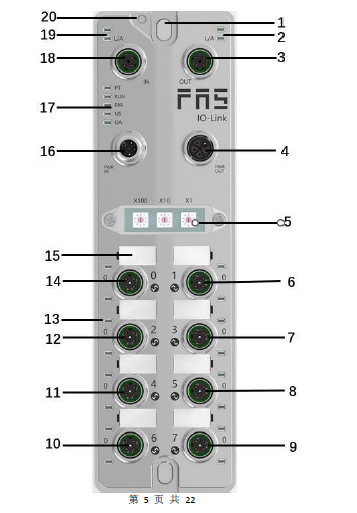
Mechanical connection
The modules are attached using 2 M6 bolts and 2 washers. Isolation pads are available as accessories.
Electrical connections
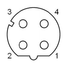
Power interface(L-code)
Definition of power input port
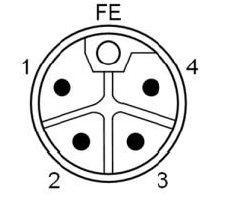
Definition of power outlet
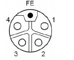
| Pin | Features | Describe |
| 1 | Us+ | +24V(BR) |
| 2 | Ua-* | 0V(WH) |
| 3 | Us- | 0V(BL) |
| 4 | Ua+* | +24V(BK) |
| FE | Functional ground* | FE(yellow-green) |
Notes:
- If possible, supply sensor/module power and actuator power separately. Total current <9A, even if the actuator power supply is daisy chained, the total current of all modules is <9A.
- The FE connection from the housing to the machine must be low impedance and kept as short as possible.
Network Interface(D-code)
| pin | features | |
| 1 | Tx+ | Send data+ |
| 2 | Rx+ | receive data+ |
| 3 | Tx- | Send data+ |
| 4 | Rx- | receive data+ |
Notes: Unused I/O port sockets must be covered with end caps to meet IP67 rating.
I/O-port(A-code)
Port0~Port7 define:
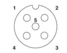
| pin | Features |
| 1 | +24V(BR) |
| 2 | Input Output(White) |
| 3 | 0V(BL) |
| 4 | Input/Output/IOLINK(BK |
| 5 | FE |
Notes:
- For digital sensor input, please follow the input guidelines of EN61131-2, Type 2.
- The maximum output current of pins 2 and 4 is 2A. The total current of the module is <9A.
- Unused I/O port sockets must be covered with end caps to meet IP67 protect
Size
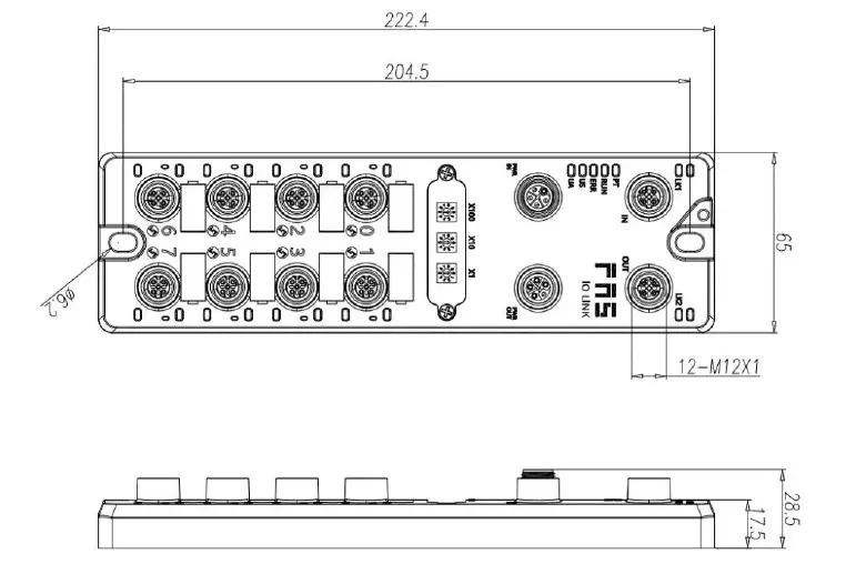
Mechanical data
| Shell material | Die-cast aluminum case, pearl nickel plated |
| Enclosure rating according to IEC 60529 | IP67(Only in plug-in or plug-in style) |
| Power interface | L-Code(male and female) |
| Input port/output port | M12,A-Code(8* female) |
| Size(W*H*D) | 65mm*222mm*25.8mm |
| Installation type | 2-Through hole mounting |
| Ground Bus Accessories | M4 |
| weight | Make an appointment670g |
Operating conditions
| Operating temperature | -5°C ~ 70°C |
| Storage temperature | -25°C ~ 70°C |
Electrical data
| voltage | 18~30V DC,symbol EN61131-2 |
| voltage fluctuation | <1% |
| Input current when supply voltage is 24V | <130mA |
Network port
| port | 2 x 10Base-/100Base-Tx |
| port connection | M12,D-Code |
| IEEE 802.3 Compliant Cable Types | Shielded twisted pair, minimum STP CAT 5/STP CAT 5e |
| Data transfer rate | 10/100 M bit/s |
| Maximum cable length | 100m |
| Flow control | Half condition/full condition (IEEE 802.3- PAUSE) |
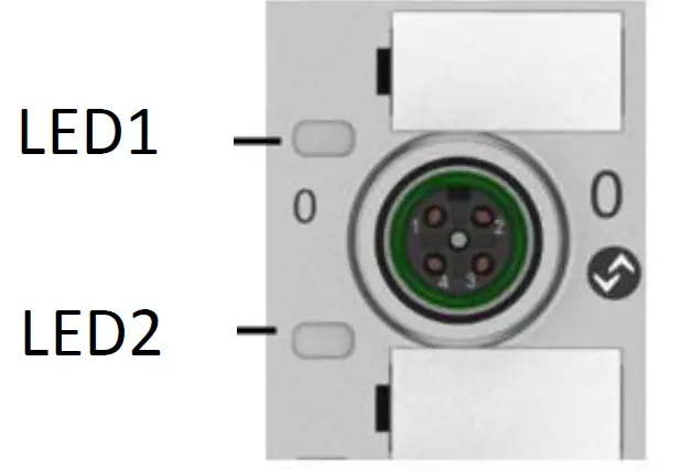
function indicator
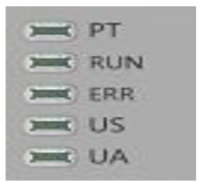
| PT | BLUE | EtherCat letter of agreement |
PN Communication protocol module status
| LED | show | Function |
| RUN | green light off | work normally |
| green light flashing 2.5HZ | Pre-running: The device is in a pre- running state | |
| green light flashing 1HZ | Safe operation: The device is in safe operation | |
| Steady green | Running: The device is running | |
| ERR | off | Device EtherCAT communication is active |
| Red light flashing 2.5HZ | Invalid configuration | |
| Red light flashing 1HZ | local error | |
| red double flash | Application watch timeout | |
| US | green | input voltage is normal |
| Res light flashing | input voltage is normal (< 18 V) | |
| UA | green | The output voltage is normal |
| Res light flashing | low output voltage (< 18 V) | |
| Red always on | no output voltage (< 11 V) |
| I/O port status LED | State | Features |
| 1 | Closure | The status of Pin4 input or output is 0 |
| 1 | Yellow | The status of Pin4 input or output is1 |
| 1 | Red | Port is configured as input:Pin1 overcurrent Port configured as output:Pin4 overcurrent |
| 1 | Flashing red | Port configured as output:Pin1 overcurrent |
| 1 | Green | IO Link connected |
| 1 | Flashing green | IO Link not connected |
| 2 | Closure | The status of Pin2 input or output is0 |
| 2 | Yellow | The status of Pin2 input or output is1 |
| 2 | Red | Port is configured as input:Pin1 overcurrent Port configured as output:Pin2 overcurrent |
| 2 | flashing red | Port configured as output:Pin1 overcurrent |

Network port status
| LED | State | Features |
| IN(L/A) | Flashing green | Data transmission |
| OUT(L/A) | Flashing green | Data transmission |
EtherCAT node address setting
- Set by dial code (1~192 or 401~499)
- Switch to the EtherCAT communication protocol, the X100 dial is the hundreds digit of the address, the X10 dial is the tens digit of the address, and the X1 dial is the ones digit of the address
- After dialing the code in the power-on state, it needs to be powered on again.
- Set by PLC
- Switch to the EtherCAT communication protocol, the X100 dial is 0, the X10 dial is 0, and the X1 dial is 0
- Set node address through PLC software
Technical data
PLC integrated
OmronNX1P2 Sysmac Studio integrated 这里,You will see how to integrate this module into an Omron PLC Example, take Omron NX1P2 PLC as an example
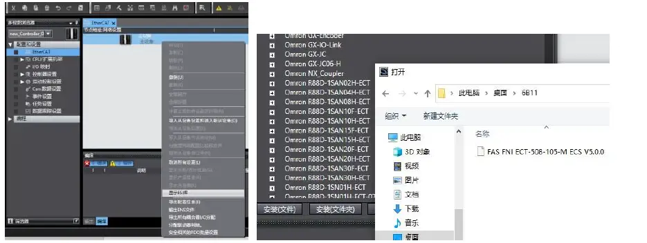
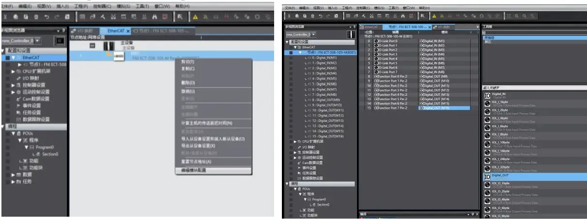
Install the ESI file: Configuration and Settings — EtherECT — Right-click the main device — Click to display the ESI library — Click “Install File” in the pop-up window — Select the corresponding product ESI file
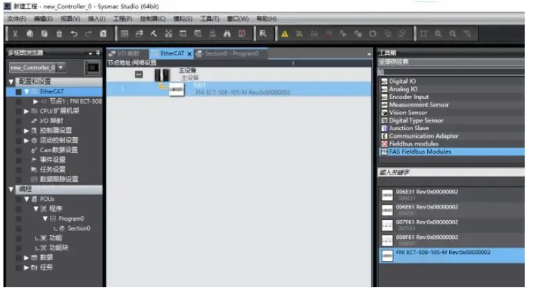
Create a module: Click on the right toolbox—find FAS Fieldbus Modules—select the product model FNI ECT-508-105-M
Double-click the corresponding product to add it to the main device
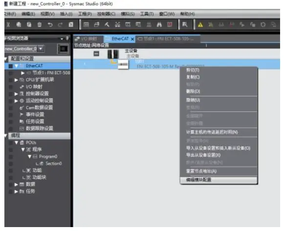
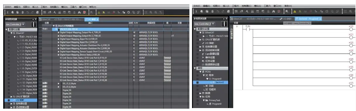
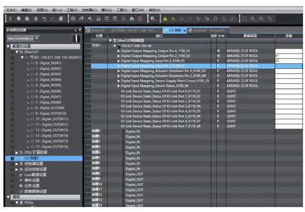
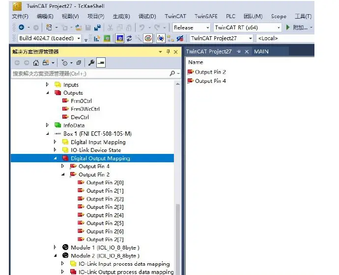
Module slot data (IOLINK mode): Right click on the module — select edit module configuration — drag the required data into the module slot — if the slave station has an output signal, open the master station PIN2 — Click on I/O Mapping — Give Digital Output Mapping_Output Pin 2 a variable — Set Output Pin 2, the port that uses output signals in the program, to 1 — the configuration is successful!
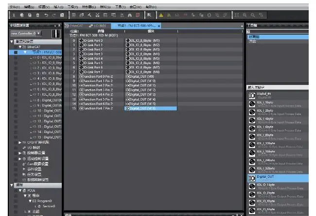
Module I/O Variables:
- Digital Output Mapping_Output Pin 4
- Digital Output Mapping_Output Pin 2
- Digital Input Mapping_Input Pin 4
- Digital Input Mapping_Input Pin 2
- Digital Input Mapping_Actuator Shutdown Pin 4
- Digital Input Mapping_Actuator Shutdown Pin 2
- Digital Input Mapping_Sensor Supply Short circuit
- Digital Input Mapping_Device Status
| byte | Equipment Process Input State Functional | ||||||||
| Function Description | Bit7 | Bit6 | Bit5 | Bit4 | Bit3 | Bit2 | Bit1 | Bit0 | |
| 0 | Standard IO input 0= no signal 1=have no | Port7 Pin4 | Port6 Pin4 | Port5 Pin4 | Port4 Pin4 | Port3 Pin4 | Port2 Pin4 | Port1 Pin4 | Port0 Pin4 |
| 1 | Standard IO input 0= no signal 1=have signal | Port7 Pin2 | Port6 Pin2 | Port5 Pin2 | Port4 Pin2 | Port3 Pin2 | Port2 Pin2 | Port1 Pin2 | Port0 Pin2 |
| 2 | short circuit detection (Pin4 overcurrent) 0= no overcurrent 1= overcurrent | – | – | – | Port3 Pin4 | Port2 Pin4 | Port1 Pin4 | Port0 Pin4 | |
| 3 | short circuit detection (Pin2 overcurrent ) 0= no signal 1=have signal | – | – | – | – |
Port3 Pin2 |
Port2 Pin2 |
Port1 Pin2 |
Port0 Pin2 |
| 4 | short circuit detection (Pin1 overcurrent ) 0= no signal 1=have signal |
Port7 Pin1 |
Port6 Pin1 |
Port5 Pin1 |
Port4 Pin1 |
Port3 Pin1 |
Port2 Pin1 |
Port1 Pin1 |
Port0 Pin1 |
| 5 | IOLink communication status 0=unconnected 1=connected | Port7 | Port6 | Port5 | Port4 | Port3 | Port2 | Port1 | Port0 |
| 6 | IOLink PD efficient 0= prohibit 1= Enable | Port7 | Port6 | Port5 | Port4 | Port3 | Port2 | Port1 | Port0 |
| 7 | module status | – | – | – | Usovervo ltage | Ua overvolt age | overvo ltage | Us undervol tage | Ua undervol tage |
Module slot data (common IO mode): right click on the module — select edit module configuration — drag the required data into the module slot (0~7: Pro0~7 PIN4 pin function, 8~15: Pro0~7 PIN2 pin function) — click I/O mapping — set the input and output variables of PIN2 and PIN4 pins of the port
As shown above, Pro0~7 PIN4 is the input setting, and Pro0~7 PIN2 is the output setting, that is, in the I/O var iable
Digital Output Mapping_Output Pin 2 Digital Input Mapping_Input Pin 4 Fill in the variables and then program in the program —- Configuration is complete!
In BECKHOFF TwinCAT XAE
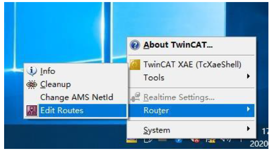
Add PLC path: Right-click the TwinCAT icon in the lower right corner to open Edit Routes
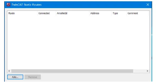
Click Add…; Add Route (Add Route Dialog)
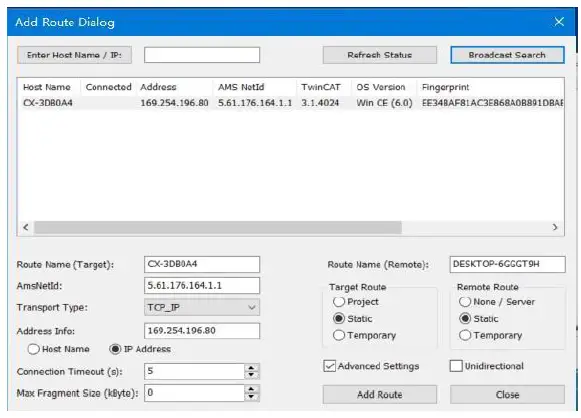
Broadcast Search-select PLC(CX-3D0A4)-Add Route
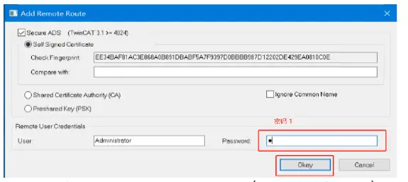
Enter the default password “1” – click OK to complete adding the PLC path
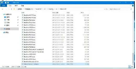
Add device configuration file: FAS FNI-ECT-508-105 (provided by FAS) Copy the file to the following path to complete the configuration file addition:
C:\TwinCAT\3.1\Config\IO\EtherCAT
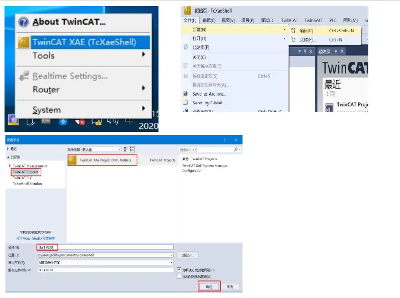
New Construction:
Open TwinCAT XAE software—File-New-Project—select TwinCAT XAE Project-enter name-OK
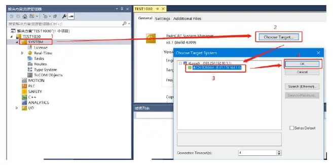
Select target system:
SYSTEM-Choose Target System-slect PLC(CX-3DB0A4)-OK
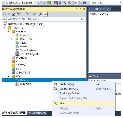
add module:
Pull down the IO option-DEVICES-SCAN; search for the master station, select Device 2(EtherCAT)-OK
Module slot data (IOLINK mode):
Find the module FNI-ECT-508-105-M under the resource manager, select Slots, select the required slot data for configuration, slots 0~7 are PIN4 functions, slots 8~15 are PIN2 functions
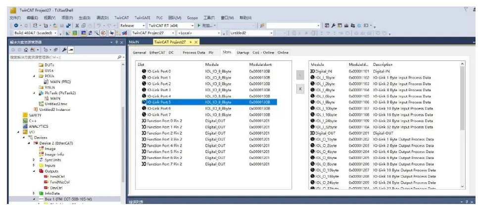
Module slot PIN2 data setting:
If the slave station module has output signal access, the master station module PIN2 must be opened, and assigned in the program —– configuration is complete! When the variable Output PIN2 is set to 1, PIN2 is enabled; when it is set to 0, PIN2 is disabled
Module slave station data setting (COE setting):
Find the module FNI-ECT-508-105-M under the resource manager and click COE-On-line
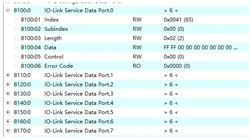
- 8100:0 :master Pro 0 Port Data Settings
- 8110:0 :master Pro 1 Port Data Settings
- 8120:0 :master Pro 2 Port Data Settings
- 8130:0 :master Pro 3 Port Data Settings
- 8140:0 :master Pro 4 Port Data Settings
- 8150:0 :master Pro 5 Port Data Settings
- 8160:0 :master Pro 6 Port Data Settings
- 8170:0 :master Pro 7 Port Data Settings
Set parameters and data according to the manual of the slave station
- moduleIndex: index
- Subindex: sub-index
- Length: Data length BYTE Type (When reading or writing, fill in the data length first)
- Data: data mapping
- Control: 1= read 2= to write
- Error code: error code
IOLINK slave station configuration (this function is online configuration, the slave station and the master station should maintain normal communication)
- When you need to configure the IOLINK slave station, you should write to set Pin4 as the IOLINK function, and write Control 2 to complete the configuration of the slave station;
Note that the input value of Index and Subindex is decimal, and the input and output value of Data is hexadecimal; - Commonly used indexing functions of FAS slaves:
Example: a. Input and output configuration: Index =65, Subindex=0; the following figure is an example of slave station configuration:
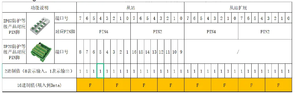
For example: the DI/DO requirement of the slave station module is full output (FFFF) Index=65 (from the station manual) Subindex=0
Length=2 Data=FFFF
Control=2 →Enter
The writing is successful, and the module configuration becomes full output
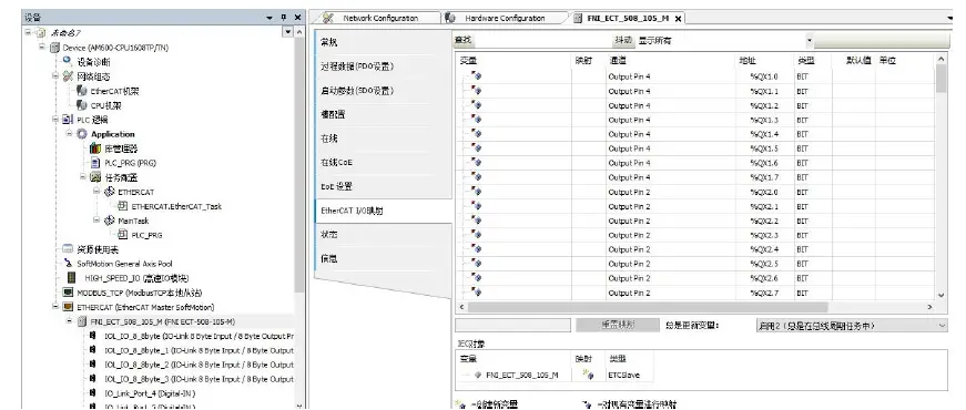
In Huichuan AM600- CPU1608TP/TN
integrated
Here you will see an example of how to integrate this module into Inproshop, taking AM600-CPU1608TP/TN PLC as an example:
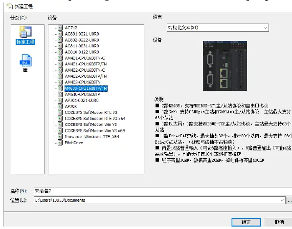
Add new project:
Select the corresponding PLC model for the new project
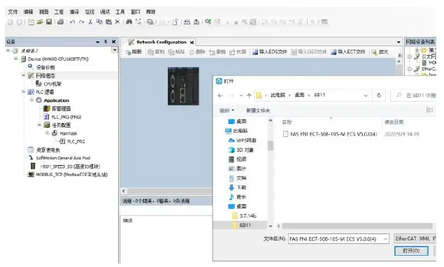
Add module:
Double-click the network configuration—-click to import ECT file—-select the master station description file FNI-ECT-508-105-M
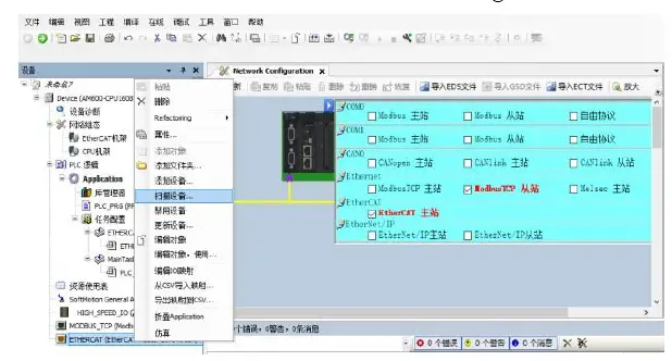
Click PLC—check the EtherCAT master station—choose the device on the left side —- -right click ETHERCAT——scan the device
Module slot data:
Double-click the left device frame module FNI-ECT-508-105-M ——Slot configuration ——Select the required slot data to configure Slot 0~7 is PIN4 function Slot 8~15 For PIN2 function
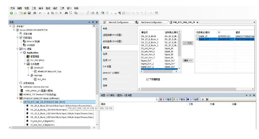
Module slot PIN2 data setting
If the slave station module has output signal access, the PIN2 of the master station module must be opened, and assigned in the program——configuration is complete! When the variable Output PIN2 address is set to 1, PIN2 is enabled; when set to 0, PIN2 is disabled
Appendix
Included materials FNI ECT contains the following components
- I/O-blocks
4 blind plugs M12 - Ground busbar
- Thread M4x6
- 20 tags
order code
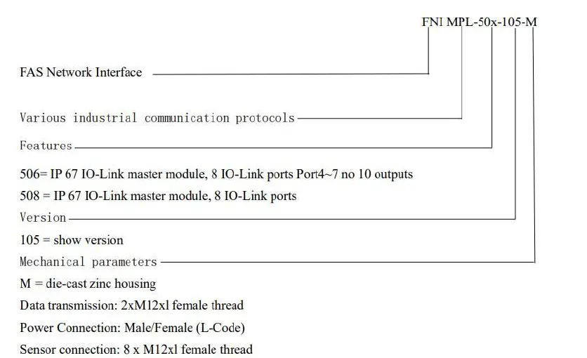
ordering information
| Product order code | order code |
| FNI ECT-508-105-M | 006B11 |


