![]()
Installation instructions
RFID compact unit
DTE601 DTE602
DTE604 DTE605
80293711 / 00 04 / 2020
Preliminary note
Technical data, approvals, accessories, and further information → www.ifm.com.
1.1 Symbols used
| ► | Instruction |
| Reaction, result | |
| […] | Designation of keys, buttons, or indications |
| → | Cross-reference |
 | Important note Non-compliance may result in malfunction or interference. |
 | Information Supplementary note |
1.2 Warnings used
ATTENTION!
Kind and source of the hazard
> Possible consequences.
► Actions to refrain from.
► Measures to take.
1.3 Copyright and trademarks
© All rights reserved by ifm electronic gmbh. No part of these instructions may be reproduced and used without the consent of ifm electronic gmbh.
All product names, pictures, companies, or other brands used on our pages are the property of the respective rights owners.
Safety instructions
- The device described is a subcomponent for integration into a system.
– The manufacturer is responsible for the safety of the system.
– The system manufacturer undertakes to perform a risk assessment and to create documentation in accordance with legal and normative requirements to be provided to the operator and user of the system. This documentation must contain all necessary information and safety instructions for the operator, the user, and, if applicable, for any service personnel authorized by the manufacturer of the system. - Read this document before setting up the product and keep it during the entire service life.
- The product must be suitable for the corresponding applications and environmental conditions without any restrictions.
- Only use the product for its intended purpose (→ Functions and features).
- If the operating instructions or the technical data are not adhered to, personal injury and/or damage to property may occur.
- The manufacturer assumes no liability or warranty for any consequences caused by tampering with the product or incorrect use by the operator.
- Installation, electrical connection, set-up, operation, and maintenance of the product must be carried out by qualified personnel authorized by the machine operator.
- Protect the device and the cables against damage.
- Use the device outside petrol stations, fuel depots, chemical plants, or blasting operations.
- Do not transport and store any flammable gases, liquids, or explosive substances near the device.
- Operation of the device can affect the function of electronic devices that are not correctly shielded.
– Disconnect the device in the vicinity of medical equipment.
– Contact the manufacturer of the corresponding device in case of any interference. - Because of the requirements for electromagnetic interference emissions, the device is intended for use in industrial environments.
The device is not suitable for use in domestic areas. - Device safety: Use the device indoors only.
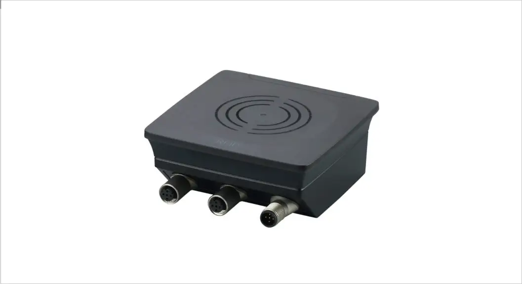
Functions and features
The DTE60x device is composed of an evaluation unit and an integrated RFID compact unit with the following functions:
- read and write ID tags that conform to the system without contact,
- DTE601: communication with the control level via PROFINET IO,
- DTE602: communication with the control level via EtherNet/IP,
- DTE604: communication with the control level via Ethernet TCP/IP,
- DTE605: communication with the control level via EtherNet IoT protocol,
- can be configured via a web server.
Example applications: - material flow control in production lines
- warehouse management by the automatic detection of stored products
- tank management, order picking, or product tracking
 The device may only be used under the operating conditions specified in the datasheet.
Configuration via Ethernet interface
- 10 Mbps and 100 Mbps
- TCP/IP – Transport Control Protocol / Internet Protocol
- IT functionality: HTTP server
- M12, twisted pair
Items supplied
- DTE60x RFID compact unit
- Installation instructions
 The device is supplied without installation and connection accessories. In the event of incomplete or damaged items supplied, please contact if electronic.
Function
5.1 Operating principle
The ID tags are operated passively, i.e. without a battery. The energy required for operation is supplied by the RFID compact unit.
The physical principle of energy transfer is based on inductive coupling. The integrated antenna coil in the RFID compact unit generates a magnetic field
that partly penetrates the antenna coil of the ID tag. A voltage is generated by induction that supplies the data carrier with energy.
5.2 Overview DTE601
 | Art. no.: | DTE601 |
| Function: | RFID compact unit | |
| Type designation: | DTRHF HLRWPNUS03 | |
| Operating frequency: | 13.56 Mhz | |
| Type: | rectangular | |
| Max. transmitter power: | 2 watts |
Fig. 1: Overview DTE601
5.3 Overview DTE602
| Art. no.: | DTE602 |
| Function: | RFID compact unit | |
| Type designation: | DTRHF HLRWEIUS03 | |
| Operating frequency: | 13.56 Mhz | |
| Type: | rectangular | |
| Max. transmitter power: | 2 watts |
Fig. 2: Overview DTE602
5.4 Overview DTE604
| Art. no.: | DTE604 |
| Function: | RFID compact unit | |
| Type designation: | DTRHF HLRWENUS03 | |
| Operating frequency: | 13.56 Mhz | |
| Type: | rectangular | |
| Max. transmitter power: | 2 watts |
Fig. 3: Overview DTE604
5.5 Overview DTE605
| Art. no.: | DTE605 |
| Function: | RFID compact unit | |
| Type designation: | DTRHF HLRWITUS03 | |
| Operating frequency: | 13.56 Mhz | |
| Type: | rectangular | |
| Max. transmitter power: | 2 watts |
Fig. 4: Overview DTE605
Installation
6.1 General installation instructions
![]() When mounting several RFID compact units adhere to the minimum distances between the systems.
When mounting several RFID compact units adhere to the minimum distances between the systems.![]() Installing an RFID compact unit in or on metal reduces the read and write distance.
Installing an RFID compact unit in or on metal reduces the read and write distance.![]() The immediate vicinity of powerful HF emission sources such as welding transformers or converters can affect the operation of the RFID compact units. Available accessories: www.ifm.com
The immediate vicinity of powerful HF emission sources such as welding transformers or converters can affect the operation of the RFID compact units. Available accessories: www.ifm.com
6.2 Notes on ID tag mounting
![]() Installation of the ID tags in and on metal reduces the read and write distances.
Installation of the ID tags in and on metal reduces the read and write distances.![]() For positioning the ID tags the RFID compact units are marked with an antenna symbol on the active face. It designates the middle of the integrated antenna coil and has to correspond with the middle of the ID tag.
For positioning the ID tags the RFID compact units are marked with an antenna symbol on the active face. It designates the middle of the integrated antenna coil and has to correspond with the middle of the ID tag.![]() The orientation of the RFID compact unit axis must correspond with the axis of the ID tag coil.
The orientation of the RFID compact unit axis must correspond with the axis of the ID tag coil.
6.3 Avoiding interference
The device generates a modulated electrical field with a frequency of 13.56 MHz. To avoid interference of the data communication no other devices generating interference emission in this frequency band must be operated in its vicinity. Such devices are for example frequency converters and switched-mode power supplies.
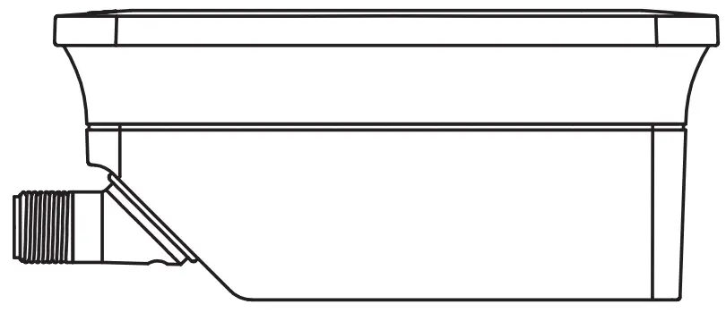
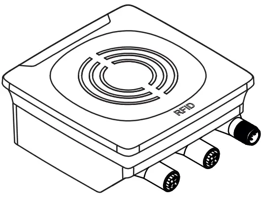
6.4 Mechanical design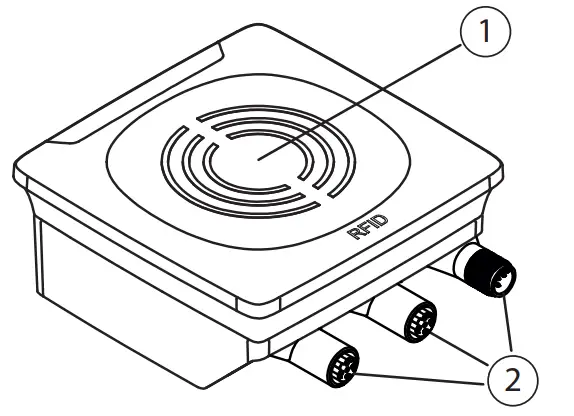
Fig. 5: Mechanical design
- sensing face
- connection (can be rotated by 270°)
6.5 Installation options
For installation, the following optional accessories are available.
The device can be mounted without the accessories. For installation, please use the threaded sleeves on the back of the device. The necessary screws are not supplied with the device.
6.5.1 Installation with angle bracket E80335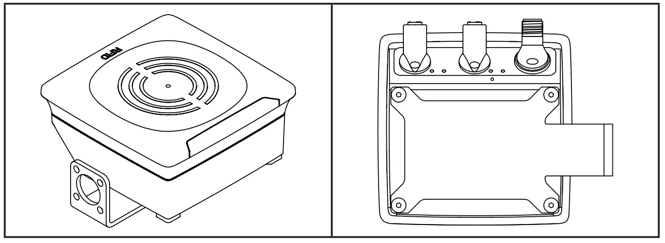 Fig. 6: Installation with angle bracket E80335
6.5.2 Installation with mounting device E80336
The mounting device is used to fix the device to a clamp. The following clamps can be used:
- E21110 with a rod diameter of 12 mm
- E20795 with a rod diameter of 14 mm
- E21109 with a rod diameter of 14 mm
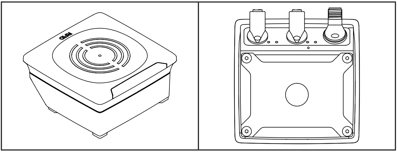
Fig. 7: Installation with mounting device E80336
6.5.3 Installation with fixing bars E80337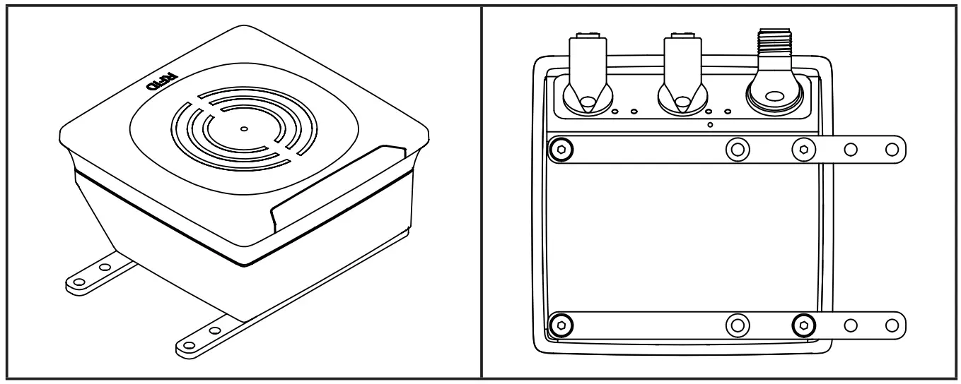
Fig. 8: Installation with fixing bars E80337
► Fix the device by fixing screws to the designated location.
6.6 Mounting distances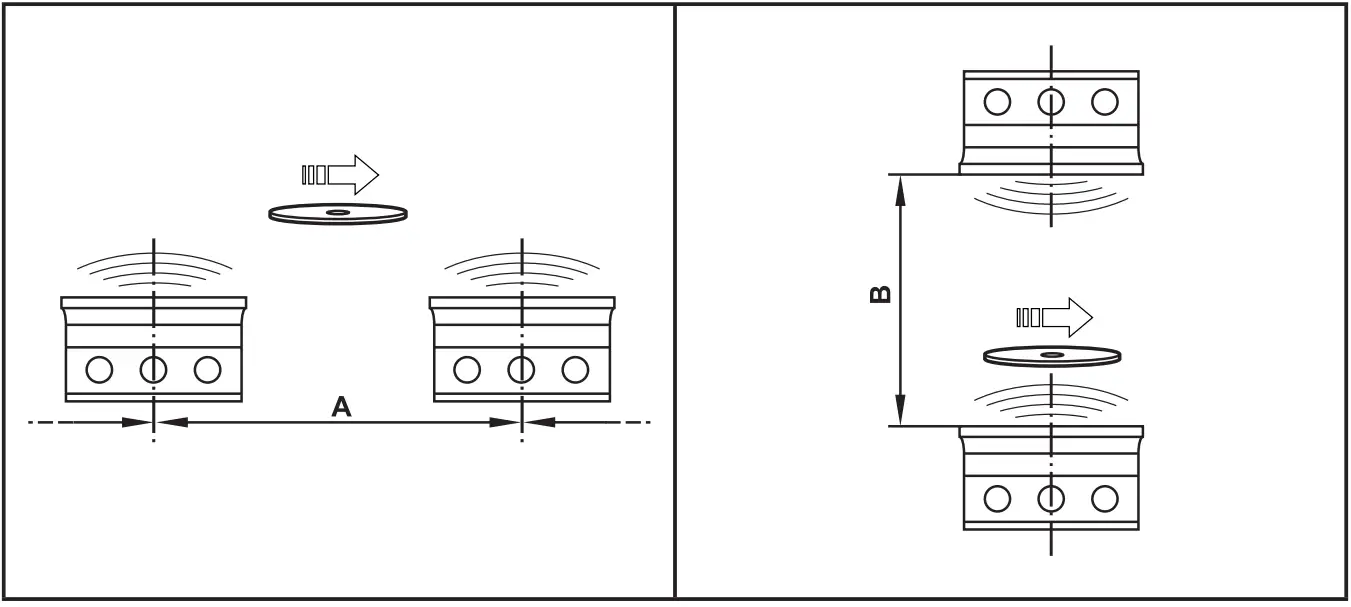
Fig. 9: Mounting distances
| Operating mode | Distance side (A) | Distance front (B) |
| Read and write (at 100% transmitter power) | ≥ 850 mm | ≥ 600 mm |
6.7 Positioning of the ID tags

Fig. 10: Position of the ID tag
► Align the ID tag on the antenna central axis.
> Distance D see datasheet
Electrical connection
NOTE
The device must be connected by a qualified electrician. The device of protection class III (PC III) is Electric supplied via SELV circuits only.
► Disconnect power before connecting the device.
► For cable lengths,> 30 m use additional protection against surge voltages to IEC 61000-4-5.
► Total current consumption of the device of 0.5 A must not be exceeded.
NOTE
The IP rating indicated in the data sheet is only guaranteed if the M12 connectors are firmly screwed.
The unit can be damaged by insufficiently tightened M12 connectors.
► Firmly screw the M12 connectors to the device.
7.1 Voltage supply PWR
► Connect the device to the voltage supply using an M12 connection cable.
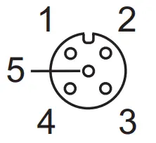 | Pin | Connection |
| 1 | 24 V DC | |
| 2 | digital input / output 2 | |
| 3 | 0 V | |
| 4 | digital input / output 1 | |
| 5 | not connected |
Fig.11: Pin connection voltage supply
Matching connection cables are available: www.ifm.com
7.2 Ethernet
► Connect the device to a PC using a suitable M12 Ethernet connection cable. The M12 Ethernet cable must be screened to ensure interference-free operation.
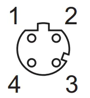 | Pin | Connection |
| 1 | TD+ | |
| 2 | RD+ | |
| 3 | TD- | |
| 4 | RD- |
Fig. 12: Pin connection Fieldbus connection
7.2.1 Factory setting of the Ethernet parameters
The following values are preset at the factory:
| Parameter | Factory setting |
| IP address | 192.168.0.79 |
| Gateway address | 192.168.0.100 |
| Subnet mask | 255.255.255.0 |
| Auto-negotiation | on |
| DHCP | off |
The settings can be changed via the web server of the device or via the PC.
7.3 Functional earth connection![]() To ensure interference-free operation, the device must be connected to an earth potential free from external voltage.
To ensure interference-free operation, the device must be connected to an earth potential free from external voltage.
7.3.1 Mounting plate
When the device is fixed on a mounting plate, the connection is made via one of the four mounting bolts on the back. Note that the plate must be connected with the earth’s potential.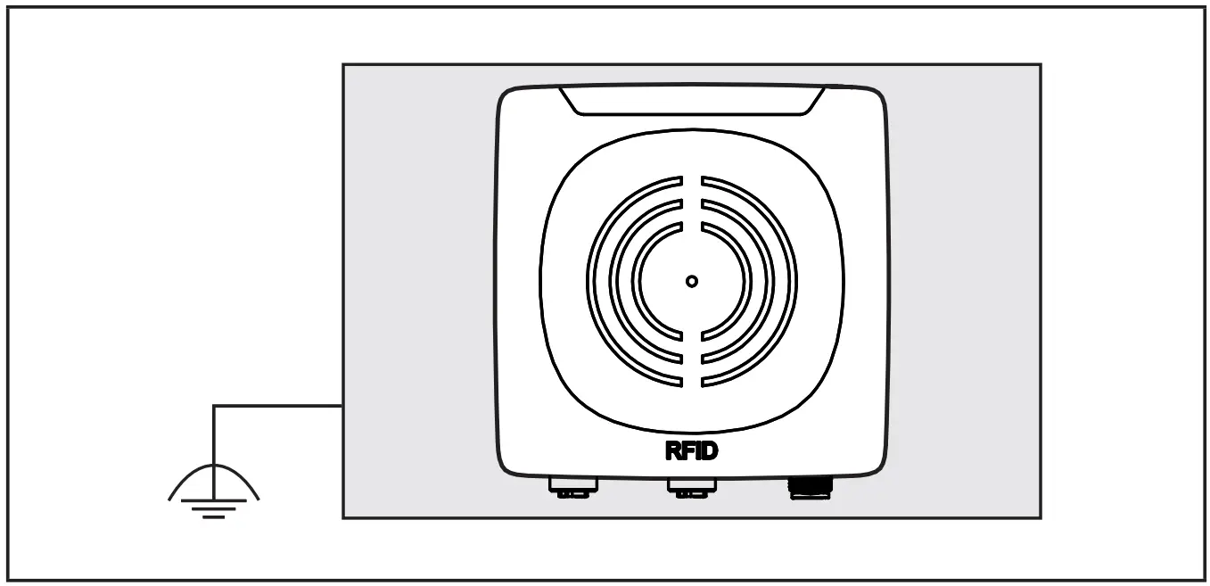
Fig. 13: Mounting plate
Operating and display elements
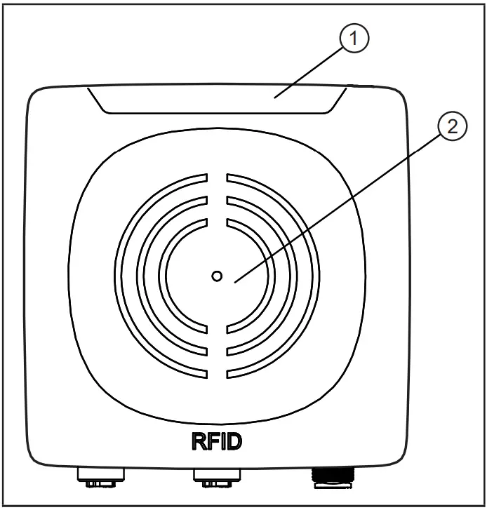
Fig. 14: Operating and display elements
- power LED (green) 4 LEDs on the signal bar (yellow)
- Fieldbus LEDs (green/red) sensing face
8.1 Reset to factory settings
The Ethernet parameters can be reset to the factory setting. To do so, proceed as follows:
► Remove all cable connections from the device.
► Insert an electrically conductive bridge between pin 2 and pin 4 on the process connection voltage supply PWR.
► Connect the device to the voltage supply.
> The LEDs of the signal bar (yellow) are on one after the other. Then LED 4 of the signal bar (yellow) flashes at 8 Hz.
► As soon as the LEDs of the signal bar (yellow) flash at 8 Hz, disconnect the device.
► Remove the bridge.
► Connect the device to the voltage supply.
> The parameters are reset.
8.2 LED indicators
The following LED indicators to apply to all DTE60x devices.
8.2.1 Power LEDs and signal bar
| LED PWR (1x green) | LED signal bar (4x yellow) | Status | Note |
| on | off | voltage supply OK | 18 V ≤ UAUX ≤ 36 V |
| flashing at 2 Hz | off | antenna (HF field) is deactivated | |
| on | flashes twice | ID tag read/written successfully | |
| on | flashing quickly | ID tag read/written incorrectly |
![]() If the ID tag has a high receive signal strength, all LEDs of the signal bar are on (configurable).
If the ID tag has a high receive signal strength, all LEDs of the signal bar are on (configurable).
![]() The maximum receive signal strength depends on the type of the ID tag.
The maximum receive signal strength depends on the type of the ID tag.
8.2.2 LED LINK/ACT ETH 1 / ETH 2
| LED green | LED yellow | Status | Note |
| off | off | no connection to another Ethernet counterpart | link status “no link”” |
| on | off | connection to Ethernet counterpart exists, no data exchange | link status “link”, “no traffic” |
| on | flashes sporadically | connection to Ethernet counterpart exists, data exchange running | link status “link”, “traffic” |
8.2.3 Special device LED indicators
| LED | Status | Note |
| PWR LED (green) on LEDs of the signal bar (yellow) flashing at 8 Hz | the device is in the service mode “emergency system started” | A firmware update is necessary and can be executed via the webserver. |
| PWR LED (green) on LEDs of the signal bar (yellow) flashing at 8 Hz | major error, the device has to be returned | hardware fault or permanent data in the device are corrupt |
| PWR LED (green) on The LEDs of the signal bar (yellow) are on one after the other. Then LED 4 of the signal bar (yellow) flashes at 8 Hz. | reset to factory settings | – |
8.3 LED indicators DTE601
The following LED indicators only apply to DTE601.
8.3.1 LED SF
| LED red | LED green | Status | Note |
| off | off | no voltage supply | check the voltage supply |
| off | flashing | “node flash test”, initiated by PROFINET 10 controller | – |
| off | on | normal operation | – |
| flashing | off | error at channel level | – overload – temperature – internal fault |
| on | off | error at the device level | – undervoltage – temperature |
| flashing | flashing | self-test | starting phase of the device |
8.3.2 LED BF
| LED red | LED green | Status | Note |
| off | off | no voltage supply | check the voltage supply |
| off | flashing | PROFINET IO controller is in STOP mode | – |
| off | on | PROFINET IO controller is in RUN mode | – |
| flashing | off | connection to the PROFINET 10 controller is established, no valid configuration | check configuration |
| on | off | no connection to the PROFINET 10 controller | check connection |
| flashing | flashing | self-test | starting phase of the device |
8.4 LED indicators DTE602
The following LED indicators only apply to DTE602.
8.4.1 LED Mod (module status)
| LED red | LED green | Status | Note |
| off | off | no voltage supply | check the voltage supply |
| off | flashing | ready for operation | The device is not configured. There is no exchange of data: ►Check the connection of the Ethernet/IP scanner. ►Check the parameter setting of the configuration assembly. |
| off | on | normal operation | Connection to the EtherNet/ IP scanner is established. The device is configured. The data transfer is running. |
| flashing | off | minor error | A connection to the EtherNet/ IP scanner was not established: ►Check the voltage supply. ►Check the configuration of the device. |
| on | off | major error | Software/hardware error of the device: ►Reboot the device. > If the error remains, send the device to the service. |
| flashing | flashing | self-test | starting phase of the device |
8.4.2 LED Net (network status)
| LED red | LED green | Status | Note |
| off | off | no IP address or no voltage supply | ►check the voltage supply ►If DHCP is activated, check the presence of a DHCP server in the network. |
| off | flashing | no connection | The device has received an IP address. An EtherNet/ IP connection was not established. ►Check the configuration of the device via EtherNet/IP scanner. |
| off | on | connection exists | At least one EtherNet/IP connection to the device was established. |
| flashing | off | timeout of the connection | A timeout was found with one of the existing EtherNet/IP connections. ►Check the status of the connection in the EtherNet/IP scanner. |
| on | off | IP address exists already | The same IP address as that of the device was detected in the EtherNet/IP network. ►Activate DHCP. |
| flashing | flashing | self-test | starting phase of the device |
8.5 LED indicators DTE604 / DTE605
The following LED indicators only apply to DTE604 / DTE605.
8.5.1 LED SF
| LED red | LED green | Status | Note |
| off | off | no voltage supply | check the voltage supply |
| off | on | normal operation | – |
| flashing | off | error at channel level | – overload – temperature – internal fault |
| on | off | error at the device level | – undervoltage – temperature |
| flashing | flashing | self-test | starting phase of the device |
8.5.2 LED BF
| LED red | LED green | Status | Note |
| off | off | no voltage supply | check the voltage supply |
| off | flashing | connection to host controller exists, there is no data exchange | – |
| off | on | connection to host controller exists, data exchange running | – |
| flashing | off | connection to host controller exists, there is no valid configuration | check configuration |
| on | off | no connection to the host controller | check connection |
| flashing | flashing | self-test | starting phase of the device |
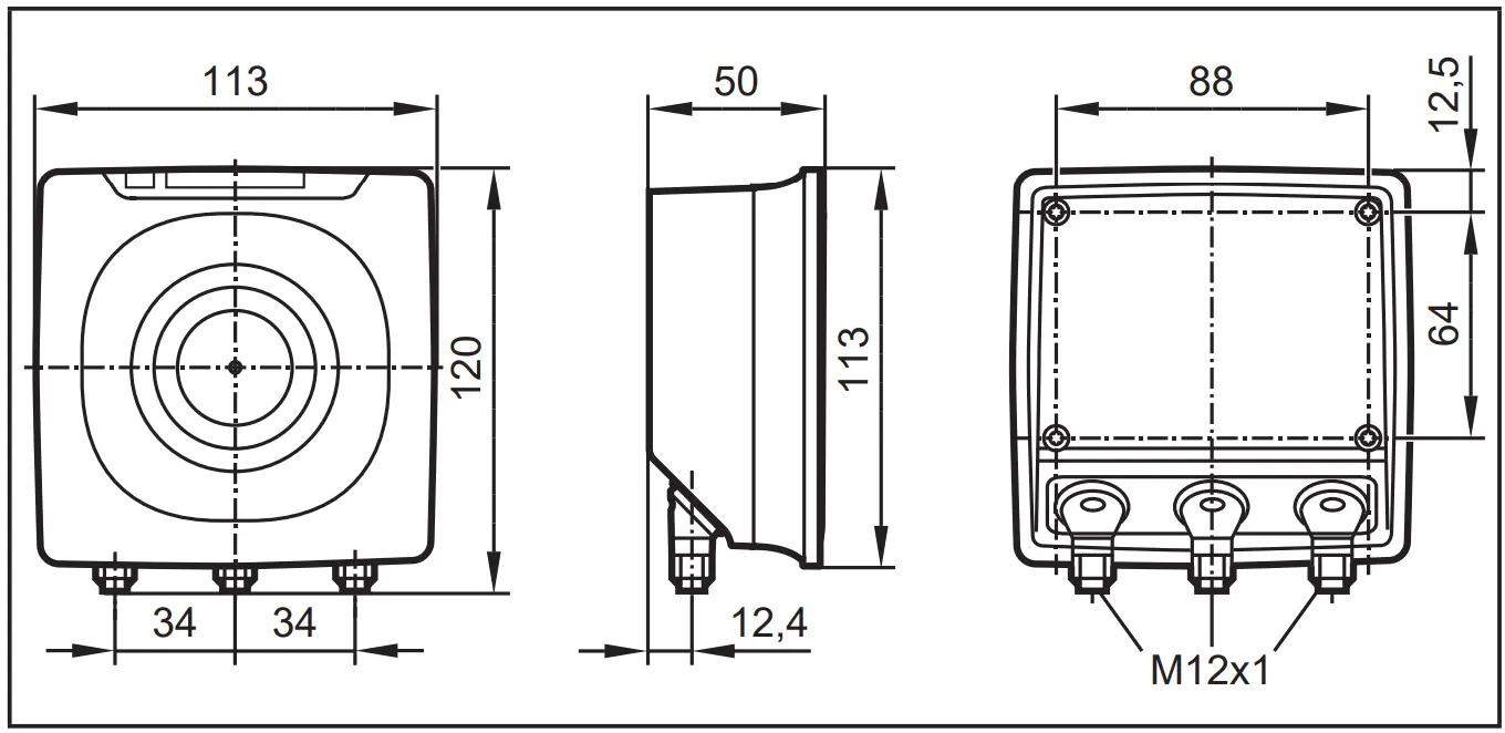
Scale drawing
Technical data
10.1 Datasheet
The datasheet is available on our website: www.ifm.com
10.2 Device manual
The device manual is available on our website: www.ifm.com
Maintenance, repair, and disposal
If used correctly, no maintenance and repair measures are necessary.
► The device must only be repaired by the manufacturer.
► After use disposes of the device in an environmentally friendly way in accordance with the applicable national regulations.
► Keep the device free from soiling.
► Use glass cleaner as a cleaning agent.
► Do not open the device.
Approvals/standards
![]() If approval is granted the approval text of the respective countries applies (→ 12 Approvals/standards). Information about the approvals granted: www.ifm.com
If approval is granted the approval text of the respective countries applies (→ 12 Approvals/standards). Information about the approvals granted: www.ifm.com
12.1 Radio approvals
12.1.1 Overview
The overview of the approval status of a unit is available on our website at www.ifm.com.
12.1.2 Europe / EC declaration of conformity
if electronic gmbh hereby declares that the DTE60x radio system corresponds to the directive 2014/53/EU. You can find the EC declaration of conformity on our website at: www.ifm.com
12.1.3 the USA
FCC note:
This device complies with Part 15 of the FCC Rules. Operation is subject to the following two conditions:
- This device must not cause harmful interference, and
- this device must accept any interference received, including interference that may cause undesired operation. Changes or modifications made to this equipment not expressly approved by ifm may void the FCC authorization to operate this equipment.
NOTE: This equipment has been tested and found to comply with the limits for a Class A digital device, pursuant to part 15 of the FCC Rules. These limits are designed to provide reasonable protection against harmful interference when the equipment is operated in a commercial environment. This equipment generates, uses, and can radiate radio frequency energy and, if not installed and used in accordance with the instructions, may cause harmful interference to radio communications. Operation of this equipment in a residential area is likely to cause harmful interference in which case the user will be required to correct the interference at his own expense.
IC note:
IC note:
This device complies with Industry Canada license-exempt RSS standards. Operation is subject to the following two conditions:
- The device may not cause interference, and
- the user of the device must accept any interference received, including interference that may cause undesired operation.
12.1.5 Taiwan
Administrative Regulations on Low Power Radio Wave Devices warning
Article 12
Unless granted permission by NCC, no company, firm, or user shall alter the frequency, increase the transmitting power or alter the original design characteristics or operating functions of an approved low-power radio-frequency device.
Article 14
Low-power radio-frequency devices shall not affect aircraft security nor interfere with legal communications. If such interference occurs, the user shall immediately cease operating the device until improvement is made and the interference no longer exists. Legal communications refer to the wireless telecommunication operations that comply with the Telecommunications Act. Low-power radio-frequency devices must accept any interference received from legal communications and ISM radio wave devices. Below are the Taiwanese legal regulations in Chinese.
![]()
12.1.6 Australia Use in Australia:
12.1.7 Singapore Complies with
IDA Standards DB 103032
The “Equipment Registration” is available on our website at: www.ifm.com


