STAHL YL6S GRP Flameproof Combination Signal

General Information
R. STAHL Schaltgeräte GmbH Business Unit Lighting & Signalling Nordstr. 10 99427 Weimar Germany
Phone:+49 3643 4324
Fax:+49 3643 4221-76
Internet:www.r-stahl.com
E-mail:[email protected]
R. STAHL Schaltgeräte GmbH Am Bahnhof 30 74638 Waldenburg Germany
Phone:+ 49 7942 943-0
Fax:49 7942 943-4333
Internet:www.r-stahl.com
E-mail:[email protected]
Information regarding the operating instructions
ID-No.:221664 / YL6S60300010
Publication Code:2018-05-24·BA00·III·en·03
- The original instructions are the English edition.
- They are legally binding in all legal affairs.
Further documents
Data sheet
For documents in additional languages, see www.r-stahl.com.
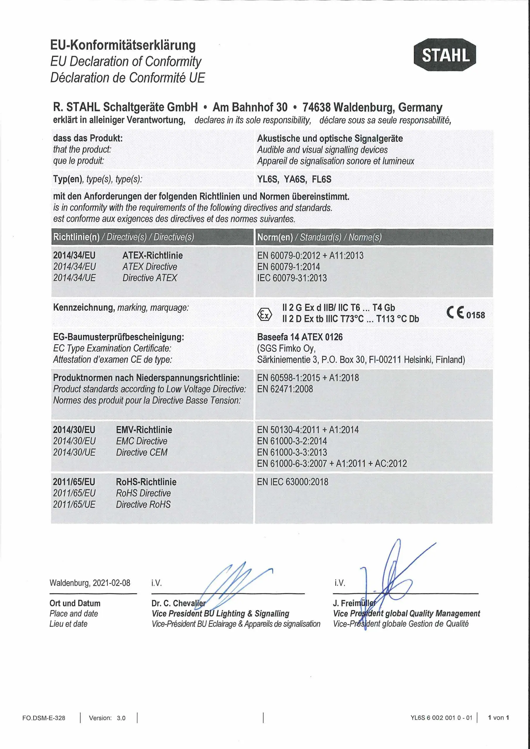
Conformity with standards and regulations
- See certificates and EC Declaration of Conformity: www.r-stahl.com.
- The device has IECEx approval. For certificate please refer to the IECEx homepage: http://iecex.iec.ch/
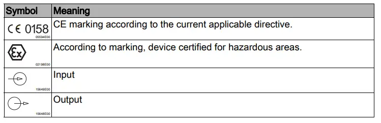
Explanation of the symbols
Symbols in these operating instructions
- Tips and recommendations on the use of the device
- General danger
- Danger due to explosive atmosphere
- Danger due to energised parts
Explanation of the symbols

Warning notes
Warnings must be observed under all circumstances, in order to minimize the risk due to construction and operation. The warning notes have the following structure:
- Signalling word: DANGER, WARNING, CAUTION, NOTICE
- Type and source of danger/damage
- Consequences of danger
- Taking countermeasures to avoid the danger or damage
DANGER
Danger to persons
Non-compliance with the instruction results in severe or fatal injuries to per-sons.
WARNING
Danger to persons
Non-compliance with the instruction can result in severe or fatal injuries to persons.
CAUTION
Danger to persons
Non-compliance with the instruction can result in light injuries to persons.
NOTICE
Avoiding material damage
Non-compliance with the instruction can result in material damage to the device and / or its environment.
Symbols on the device
Safety notes
Operating instructions storage
- Read the operating instructions carefully and store them at the mounting location of the device.
- Observe applicable documents and operating instructions of the devices to be connected.
Safe use
- Read and observe the safety notes in these operating instructions!
- Observe characteristic values and rated operating conditions on the rating and data plates!
- Observe additional information plates on the device!
- Use the device in accordance with its intended and approved purpose only!
- We cannot be held liable for damage caused by incorrect or unauthorized use or by non-compliance with these operating instructions.
- Before installation and commissioning, make sure that the device is not damaged!
- Work on the device (installation, maintenance, overhaul, repair) may only be carried out by appropriately authorized and trained personnel.
Modifications and alterations
DANGER
Explosion hazard due to modifications and alterations to the device! Non-compliance results in severe or fatal injuries.
- Do not modify or alter the device.
No liability or warranty for damage resulting from modifications and alterations.
Function and device design
DANGER
Explosion hazard due to improper use! Non-compliance results in severe or fatal injuries.
- Use the device only according to the operating conditions described in these operating instructions.
Function
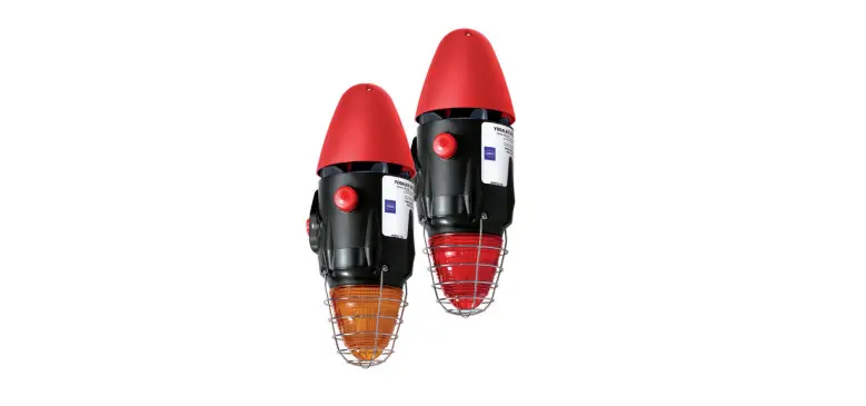
Product Series YL6S is designed to provide both an audible and visual alarm which can be used to alert, warn or draw attention to machine malfunction/start up or any number of safety related issues. The audible and visual signals can be operated independently or as a combination unit. Corrosion resistance is a key feature of the device which is ideally suited for applications in the harshest of environments both onshore and offshore. The optical element of the device must be regarded as a supplementary alarm indicator when used for alerting/evacuating the occupants of the buildings/structures.
In hazardous areas the devices have explosion protection for ATEX/IECEx Zones 1 & 2 for gas and 21 & 22 for dust. Gas groups covered are IIB & IIC, dust protection for IIIC.
- The device is not intended for continuos use.
- The life of the xenon flash tube is guaranteed for the following number of flashes:
Variant Number of flashes 5 J 2 million
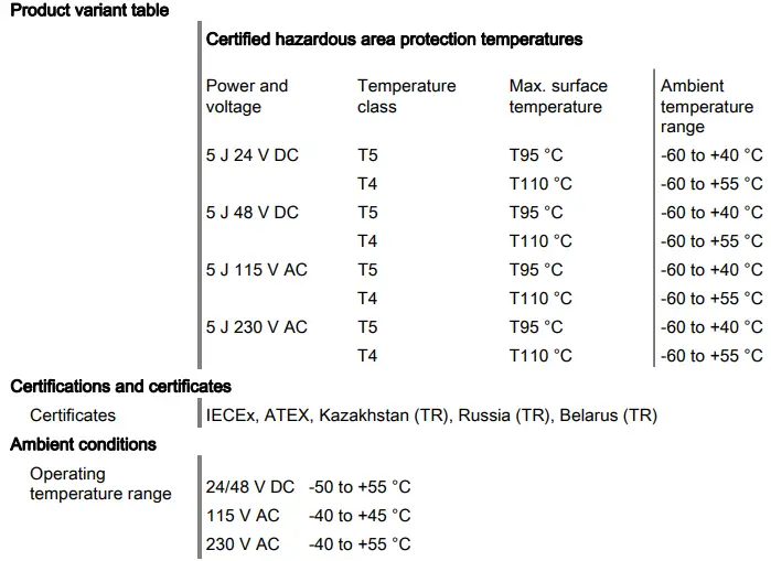
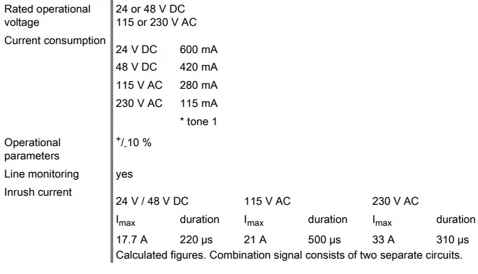
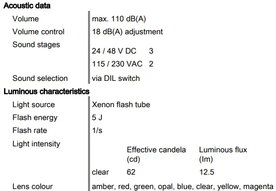
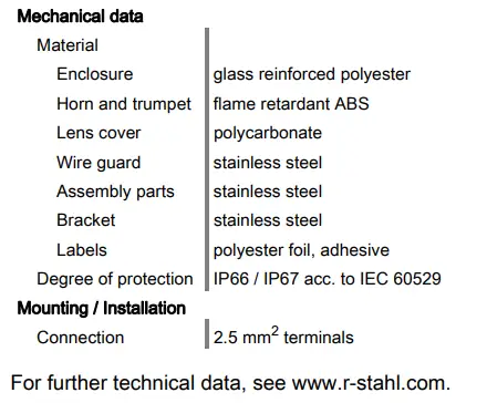
Technical data
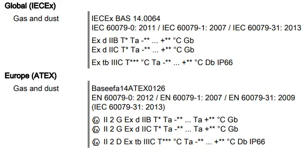
Explosion Protection
Transport and storage
- Transport and store the device only in the original packaging.
- Store the device in a dry place (no condensation) and vibration-free.
- Do not drop the device.
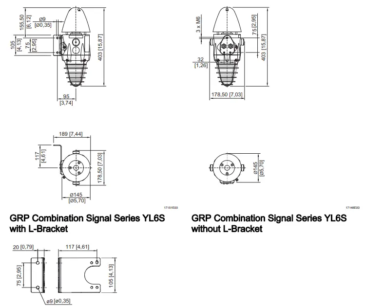
7 Mounting and installation
Dimensions / fastening dimensions
Dimensional Drawings (All Dimensions in mm [inches]) – Subject to Alterations
Mounting / dismounting, operating position
DANGER
Risk of explosion!
Risk of injuries and material damage!
- Terminal sleeves are fitted, they must be gas-tight and applied with a suitable tool.
DANGER
Explosion hazard!
Risk of injuries and material damage!
- Carefully remove or replace the components.
- Exposed joint surfaces must not be damaged and must be protected from dust and dirt.
- Install the end flanges squarely without applying any force. Do not use a hammer or other tools when working on the flanges and do not use the fixing screws to pull down the flanges.
- Mount the device on a flat surface suitable for its weight.
- Insert the cables using certified and flameproof cable glands which are suitable for the gas group.
- Close unused entries using certified and flameproof stopping plugs.
Installation Conditions for Electrical Connection
DANGER
Explosion hazard!
Risk of injuries and material damage!
- Only use cable glands with corresponding certificate. The cable glands must be flameproof (Ex d) and suitable for the type of cable used.
- Close unused open holes in the enclosure with flameproof stopping plugs.
- Close unused cable glands using flameproof plugs.
- Cable glands, stopping plugs and plugs must meet the requirements of IEC/EN 60079-14.
- Installation of the cable gland must be performed in accordance with the manufacturer’s instructions.
- Cable entry temperature may reach 70 °C.
- To ensure degree of protection IP 66, a non-hardening sealant must be applied to the threads.
DANGER
Danger due to energised parts! Risk of death or severe injuries!
- Before opening and dismounting the device, disconnect it from the power supply.
- Secure the device against unauthorized switching.
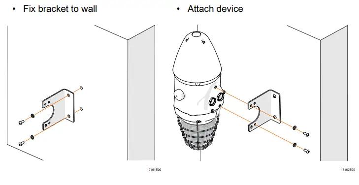
Installation with mounting bracket
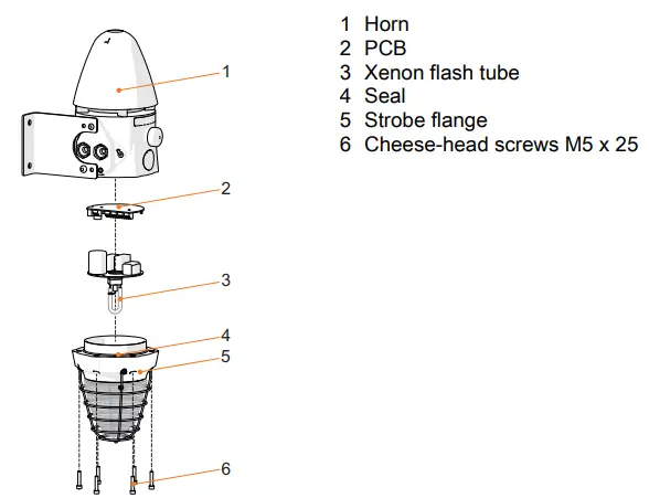
Loosen 6 x cheese head screws (6) and remove strobe flange 6 x M5 (5)
Access to the M5 cheese head screws is obscured by the wire guard. Use a ball end Allen key to allow for the off-axis angle which is required.
- Prepare cable gland
- Ensure earth connection
- Install cable gland
- Connect cables (see electrical connection)
Reassembly of Enclosure
- Lift strobe flange towards device.
- Connect PCB using the plug.
- Install strobe flange.
- Replace cheese-head screws M5 x 25 (see information below) and tighten the screws with a tightening torque of 4 Nm.
- Correct reassembly of the unit is required to ensure ingress protection to IP 66.
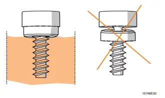
- Cheese-head screws (see chapter Acess above) are supplied with Nyltite washers.
- Before reassembly inspect Nyltite for damage.
- Check orientation is correct as per diagram.
- Cheese-head screws should be tightened with correct torque.(see above)
- Each Nyltite should not have torque applied more than 5 times.

Electrical Connection
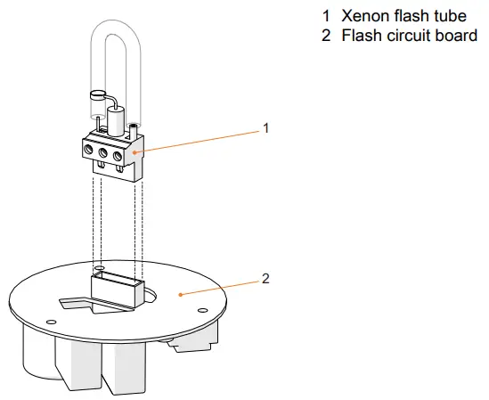
Key Components
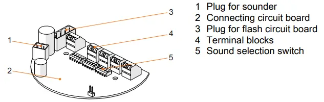
- 1 Xenon flash tube
- 2 Flash circuit board
 Key components YL6S
 - Do not touch the Xenon flash tube at anytime during the installation/assembly of the device.
Cable Connection - The terminals accept wires of 2.5 mm2 or 14 to 18 AWG.
Interconnection of devices parallel
Up to 10 devices with common supplies may be connected as a single system loop. See wiring diagrams for further information.
Circuit diagrams
Line monitoring for devices with DC - by reverse polarity
- by connecting an EOL resistor between 0 V and +V.
- The resistance value is defined by the system developer.
Two signal levels for devices with AC - by connecting the third wire
Three signal levels for devices with DC - by connecting the third and fourth wire.
 Key components YL6S
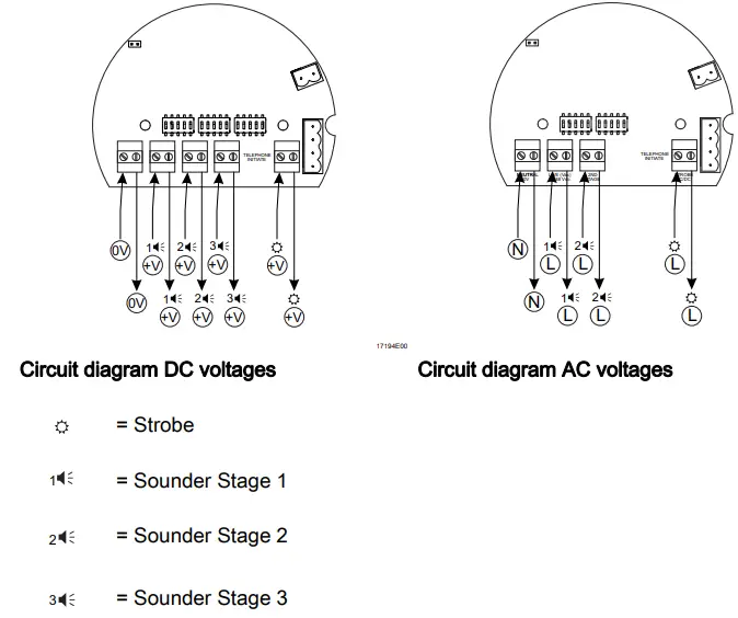
Earth Connection
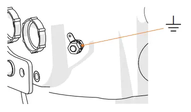
Earth connection
Use of metallic cable glands
A slip on earth tag is provided with each device. This should be connected to the external earth stud detailed above.
Device material
The GRP material used for the device enclosure has electrically conductive properties. The material is antistatic and prevents build-up of electrical charges on its surface. Surface resistivity < 108 Ω accordance to IEC 60093
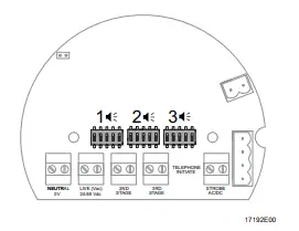
Sound Tone Selection
- For signal tone selection and its switch positions refer to the table below.
- Check if the correct switch positions of the selected signal tones have been selected.
- Do not use tone 12, 14 and 32 for AC variants.
Tone table Tone no.
Version
Frequency
Sound selection switch 12345 (ON = 1)
Repeti– tion rate (sec) Special application
Tone 01 Alternate two-tone 800-1000 11111 0.5 Fire alarms – Level crossing Tone 02 Alternate two-tone 2500-3100 01111 0.5 Security alarms Tone 03 Alternate fast two-tone 800-1000 10111 0.25 Increased urgency – Level crossing Tone 04 Alternate fast two-tone 2500-3100 00111 0.25 Security deterrent Tone 05 Alternate two-tone 440-554 11011 0.4/0.1 AFNOR, France Tone 06 Alternate two-tone 430-470 01011 1.0 Tone 07 Alternate very fast two-tone 800-1000 10011 0.13 Tone 08 Alternate very fast two-tone 2500-3200 00011 0.07 Tone 09 Alternate two-tone 440-554 11101 2.0 Turn out, Sweden (SS 031711) Tone 10 Continuous tone 700 01101 All clear, Sweden (SS 031711) Tone 11 Continuous tone 1000 10101 Tone 12 Continuous tone 1000 00101 Tone 13 Continuous tone 2300 11001 Tone 14 Continuous tone 440 01001 Tone 15 Interrupted tone 1000 10001 2.0 Tone 16 Interrupted tone 420 00001 1.25 AS2220, Australia Tone 17 Interrupted tone 1000 11110 0.5 Tone 18 Interrupted tone 2500 01110 0.25 Tone 19 Interrupted tone 2500 10110 0.5 Tone table Tone 20 Interrupted tone 700 00110 6/12 Important message, Sweden Tone 21 Interrupted tone 1000 11010 1.0 Tone 22 Interrupted tone 700 01010 4.0 Air-raid alarm, Sweden Tone 23 Interrupted tone 700 10010 0.25 Local warning, Sweden Tone 24 Interrupted tone 720 00010 0.7/0.3 Industrial alarm, Germany Tone 25 Interrupted, fast, rising volume 1400 11100 0.25 Tone 26 Fast siren 250-1200 01100 0.085 Tone 27 Rising constantly, falling 1000 10100 10/40/10 Industrial alarm, Germany Tone 28 ISO 8201 Evacuation 800-1000 00100 As standard International evacuation alarm Tone 29 Fast whoop 500-1000 11000 0.15 Tone 30 Slow whoop 500-1200 01000 4.5 Evacuation, The Netherlands
Tone 31 Reverse sweep 1200-500 10000 1.0 Fire alarm, Germany (DIN 33404) Tone 32 Siren 500-1200 00000 3.0
The PFEER sound signals recommended by UKOOA are:
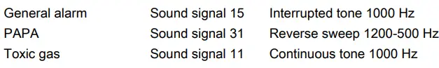
Details sound selection switch
Installation
WARNING
Danger of electric shock due to energised parts!Non-compliance can result in severe or fatal injuries.
- All connections and wiring must be disconnected from the power supply.
- Secure the connections against unauthorized switching.
DANGER
Explosion hazard!
Risk of injuries and material damage!
- Operate the device only if it is not damaged.
- If the thread is damaged, the device must be replaced immediately.
- Handle the device and the components very carefully.
- Exposed joint surfaces must be protected from dust, dirt and damage.
- Mount the end flanges squarely and do not apply any force.
- Do not use a hammer or any other metal instruments to work on the flange.
- Do not use the fixing screws to pull down the flange.
- Install the device only in a clean and dry operating environment.
Commissioning
DANGER
Explosion hazard due to incorrect installation!Non-compliance results in severe or fatal injuries.
- Check the device for proper installation and function before commissioning.
- Comply with the national regulations.
Before commissioning, ensure the following:
- the device has been installed according to regulations.
- the power supply voltage and the rated operational voltage are identical.
- the required cable diameter for cable glands has been used.
- the cable entries and stopping plugs have been securely tightened.
- the cables are correctly connected.
- the connection has been performed correctly.
- all screws and nuts are tightened according to regulations.
- the connection chamber is clean.
- the device is not damaged.
- no foreign bodies are inside the device.
- the device is sealed according to regulations.
- flash circuit board is connected.
Operation
The device is used to warn and alert by means
- of a sound signal.
- of a visual signal.
24 V DC and 48 V DC voltage variants – visual signal
At temperatures below -40°C initial start-up and stabilization of flash frequency may be delayed.
Troubleshooting
If an error occurs please re-visit the earlier sections of this document. If the error cannot be eliminated using the mentioned procedures:
- Contact R. STAHL Schaltgeräte GmbH.
For fast processing, have the following information ready: - Type and serial number
- Purchase information
- Error description
- Intended use (in particular input / output wiring)
Maintenance and repair
WARNING
Risk of electric shock or malfunctioning of the device due to unauthorized work!
Non-compliance can result in severe injuries and material damage.
- Work performed on the device must only be carried out by appropriately authorized and qualified electricians.
Maintenance
Observe the relevant national regulations in the country of use.
- Determine the type and extent of inspections in compliance with the relevant national regulations.
- Adapt inspection intervals to the operating conditions.
The following tests and measures must be carried out during regular maintenance.
Check
- the permissible ambient temperature
- the enclosure components for formation of cracks and damage.
- its intended use
- if the conductors are clamped properly the cables for ageing and damage
- the seals for ageing and damage
Measures
- If exceeding the permissible ambient temperature or falling below the device must be taken out of operation.
- Replace the exchangeable enclosure components. If the enclosure components are non-exchangeable, the device must be taken out of operation.
- If the device is not used according to its intended use, it must be taken out of operation.
- clamp loose conductors tightly.
- replace damaged or aged cables.
- replace damaged, aged and porous seals and completely change enclosure components with foamed seal.
Repair
DANGER
Explosion hazard due to improper repair!
Non-compliance results in severe or fatal injuries.
- Repair work on the devices must be performed only by R. STAHL Schaltgeräte GmbH.
Returning the device
- Contact the responsible representative from R. STAHL.
R. STAHL’s customer service is available to handle returns if repair or service is required. - Contact customer service personally.
or - Go to the www.r-stahl.com website.
- Under “Support” > “RMA form”, select “Request RMA slip”.
- Fill out the form and send it.
Confirmation will be sent. R. STAHL’s customer service will contact you. You will receive an RMA slip after speaking with customer service. - end the device along with the RMA slip in the packaging to R. STAHL Schaltgeräte GmbH (refer to Section 1.1 for the address).
Cleaning
- Clean the device only with a cloth, brush, vacuum cleaner or similar items.
- When cleaning with a damp cloth, use water or mild, non-abrasive, non-scratching cleaning agents.
- Do not use aggressive detergents or solvents.
Disposal
- Observe national and local regulations and statutory regulation regarding disposal.
- Separate materials when sending it for recycling.
- Ensure environmentally friendly disposal of all components according to the statutory regulations.
Accessories and Spare parts
NOTE
Malfunction or damage to the device due to the use of non-original components. Non-compliance can result in material damage.
- Use only original accessories and spare parts from R. STAHL Schaltgeräte GmbH.
- For accessories and spare parts, see data sheet on our homepage www.r-stahl.com.