![]() Instruction Manual
Instruction Manual
D103829X012 February 2015
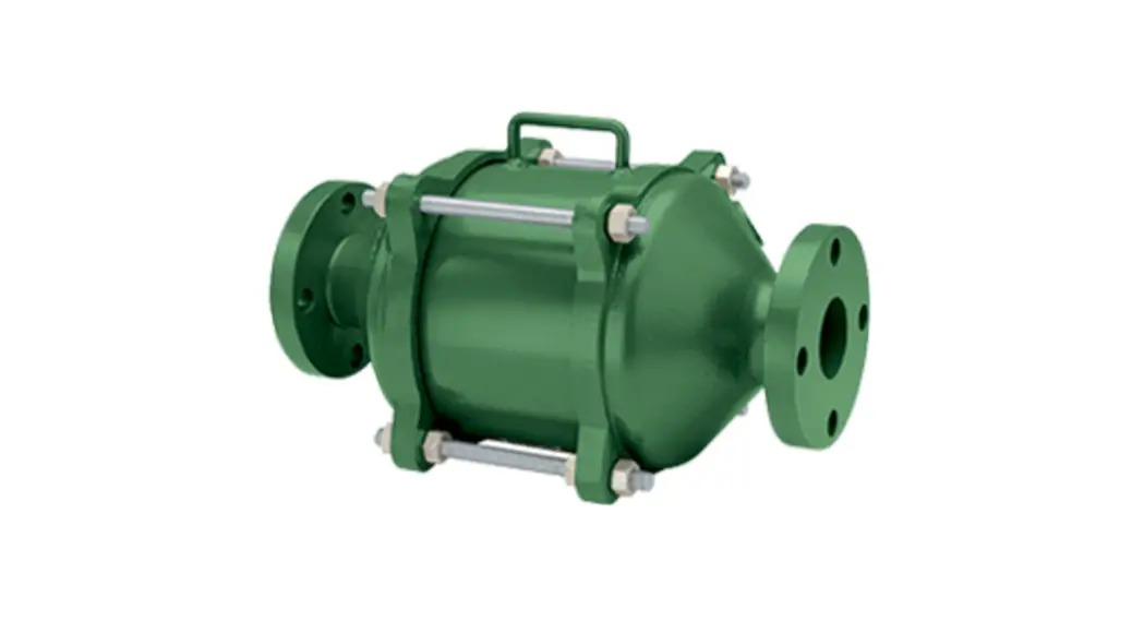
7 Series Flame Arrestor
![]() WARNING
WARNING
Failure to follow these instructions or to properly install and maintain this equipment could result in an explosion, fire, and/or chemical contamination causing property damage and personal injury or death.
Enardo flame arrestors must be installed, operated, and maintained in accordance with federal, state, and local codes, rules, and regulations and Emerson Process Management Regulator Technologies Tulsa, LLC (Emerson) instructions.
Call a qualified service person to service the unit. Installation, operation, and maintenance procedures performed by an unqualified person may result in improper adjustment and unsafe operation. Either condition may result in equipment damage or personal injury. Only a qualified person shall install or service the 7 Series flame arrestor.
Introduction
Scope of the Manual
This Instruction Manual provides specifications, installation and maintenance instructions, and parts ordering information for the 7 Series flame arrestor.
Product Description
7 Series flame arrestors are designed to stop the propagation of confined low-pressure deflagration. The 7 Series is typically used for end-of-line and near end-of-line applications when the system operating pressure is near atmospheric levels and when there is minimal probability of a flame stabilizing on the flame arrestor element for an extended period.
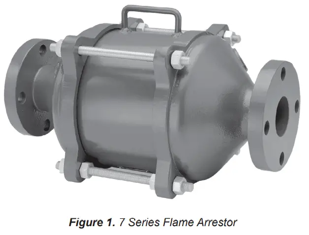
Designed with flanged connections, this arrestor allows removal of the flame cell element for easy cleaning and replacement without removing the arrestor body from the pipe connection. Standard housing construction is aluminum, carbon steel or
Specifications
The Specifications section lists the specifications for the 7 Series. The specification is stamped on the nameplate attached to the flame arrestor.
| Available Construction See Table 1 and Figure 2 Gas Group B, C and D Flange Size and Rating 1 to 36 in. / 25 to 900 mm CL150 FF and RF Housing Size 4 to 72 in. / 100 to 1800 mm Temperature Rating of Gaskets(1) Fiber Gaskets (standard): 450°F / 232°C Graphite Gaskets (Optional): Higher temperature | Pipe Length See Table 4 Housing Material Aluminum, Carbon steel, 304 Stainless steel, 316 Stainless steel and Hastelloy® Cell Material Aluminum, 304 Stainless steel, 316 Stainless steel and Hastelloy® |
1. The pressure/temperature limits in this Instruction Manual and any applicable standard or code limitation should not be exceeded.
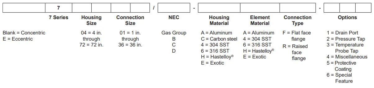 Figure 2. 7 Series Flame Arrestor Available Constructions and Model Numbering System
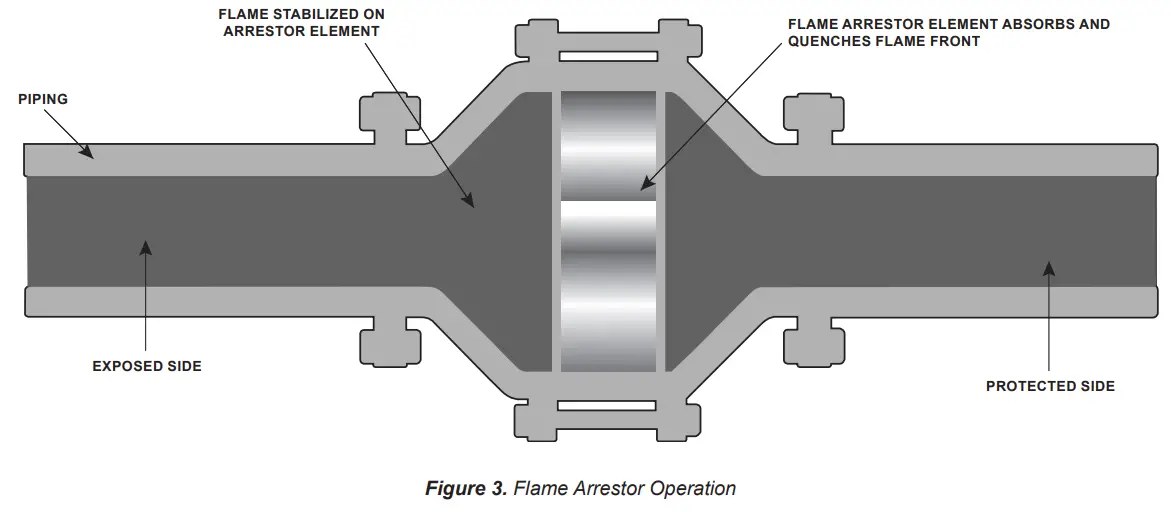
Table 1. 7 Series Available Construction
| 7 SERIES IN-LINE FLAME ARRESTOR CARBON STEEL AND STAINLESS STEEL HOUSINGS CONSTRUCTION | ||||
| Model | Flange Size | Housing Size | ||
| In. | mm | In. | mm | |
| 70401 | 1 | 25 | 4 | 100 |
| 70402 | 2 | 50 | 4 | 100 |
| 70602 | 2 | 50 | 6 | 150 |
| 70802 | 2 | 50 | 8 | 200 |
| 70603 | 3 | 75 | 6 | 150 |
| 70803 | 3 | 75 | 8 | 200 |
| 70804 | 4 | 100 | 8 | 200 |
| 71006 | 6 | 150 | 10 | 250 |
| 71206 | 6 | 150 | 12 | 300 |
| 71408 | 8 | 200 | 14 | 350 |
| 71608 | 8 | 200 | 16 | 400 |
| 71810 | 10 | 250 | 18 | 450 |
| 72010 | 10 | 250 | 20 | 500 |
| 72212 | 12 | 300 | 22 | 550 |
| 72412 | 12 | 300 | 24 | 600 |
| 7 SERIES IN-LINE FLAME ARRESTOR ALUMINUM HOUSING CONSTRUCTION | ||||
| Model | Flange Size | Housing Size | ||
| In. | mm | In. | mm | |
| 70802 | 2 | 50 | 8 | 200 |
| 70803 | 3 | 75 | 8 | 200 |
| 70804 | 4 | 100 | 8 | 200 |
| 71006 | 6 | 150 | 10 | 250 |
| 71206 | 6 | 150 | 12 | 300 |
| 71408 | 8 | 200 | 14 | 350 |
| 71608 | 8 | 200 | 16 | 400 |
| 72010 | 10 | 250 | 20 | 500 |
| 72212 | 12 | 300 | 22 | 550 |
| 72412 | 12 | 300 | 24 | 600 |
stainless steel. The element is available in stainless steel. Special material and protective coating are available on request.
Principle of Operation
A flame arrestor allows gas to pass through it but stops flame in order to prevent a larger fire of explosion. Arrestor prevents flame by absorbing and dissipating the heat from flame as it attempts to travel through the spiral wound crimped ribbon flame cells. These cells allow maximum flow with maximum protection.
Factors Affecting Flame
Arrestor Performance
Gas Group
![]() WARNING
WARNING
Methanol is classified by the National Electrical Code (NEC) as a Group-D vapor. However, our lab tests indicate that methanol exhibits characteristics, unlike other Group-D vapors under certain conditions. We, therefore, recommend that an arrestor rated for Group-C vapors be specified for methanol service.
Table 2. Maximum Experimental Safe Gap (MESG)
| NATIONAL ELECTRICAL CODE (NEC) | MEG | TEST GAS LIST | |
| In. | mm | ||
| Group B | 0.011 | 0.28 | Hydrogen |
| Group C | 0.026 | 0.65 | Ethylene |
| Group D | 0.035 | 0.90 | Propane |
Table 3. 7 Series Flame Arrestor Endurance Burn Time
| GAS GROUP | MAXIMUM INITIAL PRESSURE | ENDURANCE BURN TIME | |
| psia | hPa | ||
| D | 15. | 106 | 30 minutes (Steel and Stainless steel models up to 12 in. and under) |
| D | 15. | 106 | 5 minutes (all other Group-D) |
| C | 15. | 106 | 5 minutes |
| B | 15. | 106 | 2 minutes |
The type of gas in the system determines its gas grouping and therefore predetermines the type of arrestor element required. The element must be designed to accommodate the specific gas group that could possibly ignite and propagate in the system. The more explosive gases require the flame cell to absorb the heat more quickly and efficiently. The National Electrical Code (NEC) groups gases into A, B, C, D, and G.M. categories depending on the Maximum Experimental Safe Gap (MESG) of the gas.
Maximum Experimental Safe Gap (MESG)
![]() WARNING
WARNING
Verify that the Flame Arrestor being installed has the appropriate gas group rating for your process. This information is shown on the nameplate attached to the element housing. Do not remove or alter this nameplate.
The measurement of the maximum gap between two equatorial flanges on a metal sphere will prevent a flame from being transmitted from the sphere to the surrounding flammable mixture. MESG is dependent on gas composition. The stoichiometric mixture (the ideal air/fuel ratio for the most efficient combustion) is used to determine the minimum MESG for a given gas. See Table 2 for the MESG per gas group.
Maximum Initial Operating Pressure
This is the pressure of the system at or near static flow conditions. A high-pressure deflagration can occur more easily at the higher system operating pressures than at pressures near the atmosphere. Elevated pressures condense the ignitable gas giving the flame more matter and energy to release thereby boosting the flame heat intensity. Verify that your system pressure at or near static flow conditions does not exceed the maximum pressure shown on the arrestor’s name tag.
Endurance Burn Time
![]() WARNING
WARNING
Unlimited burning should not be allowed in any flame arrestor, regardless of its burn time rating. If burning can occur for a period exceeding 2 minutes starting at ambient temperature, it is recommended that a temperature alarm and shutdown system be installed.
Endurance burn time is the time it takes for a stabilized flame, at the greatest heat saturation conditions, to heat the arrestor element above the auto-ignition temperature of the process gas stream resulting in flame propagation through the arrestor. See Table 3 for the 7 Series endurance burning time.
Table 4. 7 Series Pipe Length Rules
| GAS GROUP “B” | GAS GROUP “C” | GAS GROUP “D” | |
| The maximum length of pipe between the flame arrestor and the ignition source without bends or other obstructions. | 4 ft. / 1.2 m., open-ended pipe | 6 ft. / 2 m., open-ended pipe | 20 ft. / 6 m. |
| The maximum length of pipe between the flame arrestor and the ignition source with a maximum of one 90° bend. Multiple bends or any additional obstructions are not recommended. | Not Recommended With a Bend. | 6 ft. / 2 m., open-ended pipe | 20 ft. / 6 m. |
Pipe Lengths
Extended lengths of pipe allow the flame to advance into more severe states of flame propagation such as high-pressure deflagration or detonations. 7 Series Flame Arrestors should be installed in accordance with Table 4.
Bends and/or Flow Obstructions
![]() CAUTION
CAUTION
For maximum safety, avoid bends and flow obstructions within 10 pipe diameters on the protected side of the flame arrestor.
Bends in piping, pipe expansions and/or contractions, valves, orifice plates or flow obstructing devices of any kind contribute to turbulent flow. Turbulent flow enhances the mixing of combustible gases, greatly increasing the combustion intensity. This can result in increased flame speeds, higher flame temperatures, and higher flame front pressures than would occur in normal flow conditions.
Installation
![]() WARNING
WARNING
Always make sure that the system is at atmospheric pressure and that there is no ignitable gas that could flash when either installing or maintaining the unit.
Connection
Enardo flame arrestors are normally provided with CL150 raised or flat face flanges. Other flange patterns are available upon request. Make sure the companion flanges installed in adjacent piping match the flanges on the flame arrestor.
Standard compressed fiber gaskets that withstand temperatures of 450°F / 232°C are standard. Graphite gaskets with higher temperature ratings are available as an option.
Positioning
![]() CAUTION
CAUTION
The flame arrestor is fitted with lugs for lifting the element assembly during servicing operations. These lugs are not intended for lifting the entire unit during installation. Damage to the flame arrestor may result from improper lifting. Heavy units should be lifted using appropriately rated Nylon (PA) straps rigged on the outside of the tension studs.
The flame arrestor should be positioned such that the element is accessible for removal. The tension studs are supplied with jacking nuts on one half of the bolting circumference. Install the unit so that the jacking nuts (on the inside of the studs) are positioned on the opposite side from the direction that the element assembly will be removed.
Models that have drain plugs are designed for horizontal installation and should be installed with the drain plugs aligned at the bottom of the unit. Models that have pressure taps are designed to allow pressure gauges to be installed on both sides of the flame cell assembly to determine blockage. The pressure taps should be aligned at the top to allow easy viewing of the gauges. Units that are equipped with optional internal cleaning systems should be connected to a source of cleaning media such as water, steam or another suitable solvent.
Flow Direction
The Enardo flame arrestor is bi-directional and can be installed either vertically or horizontally. Consideration should be given to non-symmetrical assemblies that include features such as clean-out ports, temperature monitoring devices,s or other options that might have a preferred installation direction to suit the needs of the customer.
Piping Expansions and Reductions
Adjacent to Flame Arrestors
![]() WARNING
WARNING
No instrument, tubing, or other device whatsoever shall circumvent the flame arrestor in such a manner to allow a flame path to exist around the flame element of the arrestor. When instrumentation is installed in such a manner that it creates a path circumventing the flame element of an arrestor, measures must be taken to prevent the passage of flame through the instrumentation device and/or system. Instrumentation must be capable of withstanding the maximum and minimum pressures and temperatures to which the device may be exposed.
An Enardo flame arrestor may be installed in any vapor control line that is smaller than or equal to the nominal pipe diameter of the arrestor’s connection flanges. When it is necessary to increase the diameter of the piping on the downstream side of the flame arrestor, a length of pipe at least 120 pipe diameters must be installed between the flame arrestor and the expansion. Pipe diameter is considered as the inside diameter of a pipe having a nominal size equal to the flame arrestor’s connecting flanges.
Maintenance
![]() WARNING
WARNING
Flame cells must be inspected for damage immediately following a deflagration and/or stabilized burn.
- Carefully remove the element assembly from the arrestor and place it on a soft surface such as plywood.
- Inspect the flame cell visually for any signs of corrosion or other damage.
- Inspect the flame cell with a calibrated pin gauge to ensure maximum crimp size openings do not exceed the following values for their respective gas group:
• Explosion Group D – 0.051 in. / 1.3 mm
• Explosion Group C – 0.038 in. / 0.965 mm
• Explosion Group B – 0.017 in. / 0.432 mm - If any damage is noted, or crimp openings exceed the maximum size allowably, replace the element assembly.
- Keep the element openings clean to prevent loss of efficiency in absorbing heat. Remove the element assembly and clean the elements to prevent the openings from becoming clogged with particulate matter. Clean the element with a suitable cleaning media (solvent, soap, water or steam) then blow dry using compressed air. Be careful not to damage or dent the cell openings as this would hamper the effectiveness of the unit. Do not clean the arrestor elements by rodding to remove blockages, as this practice will damage the elements and seriously impair the arrestor’s performance. If the arrestor element cannot be cleaned satisfactorily, replace it.
- For best cleaning results, use a high-pressure sprayer with a spray wand (1500 to 3000 psig / 103 to 207 bar) to clean the entire element surface. Hold the spray nozzle perpendicular to the surface being cleaned to maximize spray media penetration into the element. Alternately spray each side of the element surface until clean.
- The cleaning interval should be governed by the amount and type of particulate in the system to which it is installed and must be determined by the user. To determine the maintenance interval, the user should check the element in the first few months of operation to find how quickly particulate accumulates in the cells.
- After cleaning, thoroughly inspect the element for damage. If damaged, replace it.
Note Under no circumstance should the element bank be disassembled from its shell for cleaning or replacement. The element section must be replaced as a complete assembly. Cleaning of units equipped with this system may be accomplished in several ways including periodic cleaning using manually operated valves, by use of an automated cycle timing method, or by having the cleaning operation initiated whenever the pressure loss across the arrestor element exceeds a predetermined value.
Element Assembly, Disassembly and
Reassembly Instructions
![]() WARNING
WARNING
Isolate gas supply and bring the system to atmospheric pressure to prevent ignitable gas from flashing while performing maintenance.
- Loosen all jacking (inside) nuts on tension studs between conical sections of the flame arrestor.
- Tighten the inside jacking nuts on the tension studs forcing the two conical sections apart. When the two flange faces have separated, remove the tension studs that do not have inside jacking nuts so that the element assembly can be removed. The inside jacking nuts are installed on all tension studs that facilitate jacking the unit apart. The inside jacking nuts are not installed on tension studs that are taken out, for ease of removal.
 CAUTION
Element assemblies are heavy and will require the use of adequate equipment and manpower to prevent injury. - Thoroughly clean the gasket sealing faces being careful not to damage the sealing surface. For reassembly, lightly grease one side of a new gasket and place it in the machined recess of each interior flange on the two conical sections.
- Replace the flame element assembly with a new assembly or properly cleaned and inspected the existing unit.
- Loosen the jacking nuts on the tension rods until the flame cell assembly seats onto the gaskets.
- Replace all tensioning studs and hand tighten the outer nuts. Check to be sure that all the jacking nuts are completely loose and not making contact with the flange face.
Torquing Instruction
![]() CAUTION
CAUTION
Excessive or uneven torquing can cause permanent damage to gaskets and housing.
Tools/Supplies Required
- Torque wrench appropriate for the specified torque
- Socket wrenches of the proper size to fit the hex nuts being tightened
- Molydisulfide-based lubricating paste, Molykote® G-n or equivalent
- Brush suitable for applying lubricant to the studs
- Wiping rags necessary for the clean-up of excessive lubricant
Procedure
- Use studs and nuts that are free of visible contamination and corrosion.
- Apply lubricant to the threads of the stud protruding outboard of the interior flanges and to the face of the hex nuts which will contact the flange.
- Assemble the nuts to the studs such that the amount of thread extending outboard beyond the nut is approximately equal on both ends.
- Tighten the nuts to the torque values shown in Table 5 following the designated sequence, repeating the sequence as shown. Flange pattern tightening sequences are shown in Figure 4.
Bolt Lubrication
Lubrication will affect the required torque of clean fasteners in good condition more than any other factor. In fact, 90% of applied torque goes to overcome friction while only 10% actually stretches the bolt. Table 5 assumes that only machine oil is used as a lubricant. Table 6 shows a list of several common lubricants and their effect on torque required to stretch bolts to 50% of their yield strength. Most are available from local bearing distributors.
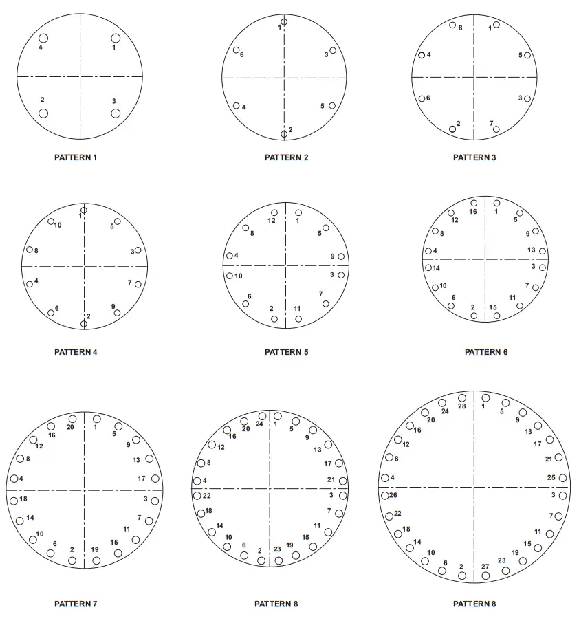
Figure 4. Flange Pattern Tightening Sequence
Table 5. Tightening Steps and Torque Values (1)(2)
| 7 SERIES FLAME ARRESTORS WITH ALUMINUM END SECTIONS ONLY | TIGHTENING STEPS AND TORQUE (LBF-FT/ N•m) | |||||
| Model | Patternm | Step 1 | Step 2 | |||
| 70802-A, 70803-A, 70804-A | 1 | Snug | 25/34 | |||
| 71006-A, 71206-A, 71408-A | 2 | Snug | 25/34 | |||
| 71608-A | 3 | Snug | 25/ 34 | |||
| 72010-A | 3 | Snug | 50/ 68 | |||
| 72212-A, 72412A, 72414-A, 72614-A, 72616-A | 5 | Snug | 50!68 | |||
| 73016-A | 7 | Snug | 50/68 | |||
| 73216-A | 8 | Snug | 50/ 68 | |||
| 7 SERIES FLAME ARRESTORS WITH STEEL OR STAINLESS STEEL END SECTIONS ONLY | TIGHTENING STEPS AND TORQUE (LBF-FT / N•m) | |||||
| Model | Pattern | Step 1 | Step 2 | Step 3 | Step 4 | I Step 5 |
| 70401, 70401.5, 70602, 70603, 70604, 70802, 70803, 70804 | 1 | Snug | 20 / 27 | 50 / 68 | ||
| 71006, 71206 | 2 | Snug | 20 / 27 | 50 / 68 | ||
| 71408 | 2 | Snug | 25 / 34 | 60 / 81 | ||
| 71608 | 3 | Snug | 25 / 34 | 50/68 | 80 / 108 | |
| 71810 | 3 | Snug | 25 / 34 | 50/68 | 90 / 122 | |
| 72010 | 3 | Snug | 25 / 34 | 50/68 | 75 / 102 | 100 / 136 |
| 72212 | 4 | Snug | 25 / 34 | 50/68 | 85/115 | |
| 72412 | 4 | Snug | 35/47 | 70/95 | 100/136 | 130 / 176 |
| 72614, 72616 | 4 | Snug | 35/47 | 70/95 | 100/136 | 140 / 190 |
| 72814 | 5 | Snug | 35/47 | 70/95 | 100/136 | 125 / 169 |
| 73016 | 5 | Snug | 35/47 | 70/95 | 100/136 | 130 / 176 |
| 73216 | 6 | Snug | 35/47 | 70/95 | 105/142 | |
| 73420 | 6 | Snug | 35/47 | 70/95 | 115 / 156 | |
| 7 SERIES FLAME ARRESTORS WITH STEEL OR STAINLESS STEEL END SECTIONS ONLY | TIGHTENING STEPS AND TORQUE (L BF-FT / N•m) | |||||
| Model | Pattern ea | Step 1 | Step 2 | Step 3 | Step 4 | Step 5 |
| 73620 | 6 | Snug | 35 / 47 | 70 / 95 | 100/ 136 | 120 / 163 |
| 74020, 74024, 74824 | 7 | Snug | 35 / 47 | 70 / 95 | 130/176 | |
| 77036 | 8 | Snug | 35/47 | 70/95 | 130/176 | 200 / 271 |
| 1. Use machine of as lubed cant. See Bolt Lubrication section (Table 6) and torque correction factors fa other lubricants. 2. See Figure 4. | ||||||
Table 6. Torque Correction Factors for Common Lubricants
| DESCRIPTION | COEFFICIENT OF FRICTION | MULTIPLY TORQUE VALUE IN TABLE 5 BY |
| Machine Oil | f= 0.15 | 1.00 |
| API SA2 Grease | f= 0.12 | 0.80 |
| Never-Seez° (Ni-base) | f = 0.11 | 0.73 |
| Never-Seez° (Cu base) | f= 0.10 | 0.67 |
| Molykote° G-n Paste | f = 0.06 | 0.40 |
Molykote® G-n is a mark owned by Dow Corning Corporation.
Never-Seez® is a mark owned by Bostik, Inc.
Recommended Spare Parts
For installations that require frequent maintenance and minimum downtime, it is recommended that the user purchase a spare element assembly and several spare element gaskets. The spare element assembly can be installed immediately and the dirty assembly can then be cleaned and be stored as a spare for the next maintenance interval.
Note
Element gaskets should be replaced each time the cell assembly is loosened and removed to ensure a gas-tight seal.
Parts Ordering
When corresponding with your local Sales Office about this equipment, always reference the equipment serial number stamped on the nameplate. When ordering replacement parts, specify the complete 7-character part number of each required part as found in the following parts list.
Parts List
Table 7. Part Numbers for Replacement Element Assembly Gaskets (for Cast Aluminum End Sections)(1)
| MODEL | PART NUMBER | |
| Standard Gasket (Compressed Fiber) | High-Temperature Gasket (Graphite Coated 316 Stainless Steel) | |
| 70802-A, 70803-A, and 70804-A | 7008102 | 7049202 |
| 71004-A | 7008135 | 7049235 |
| 71206-A | 7008136 | 7049236 |
| 71408-A | 7008124 | 7049224 |
| 71608-A | 7008107 | 7049207 |
| 1. Two (2) required per assembly. | ||
Table 8. Part Numbers for Replacement Element Assembly Gaskets (for All Fabricated End Sections) (1)
| MODEL | PART NUMBER | |
| Standard Gasket (Compressed Fiber) | High-Temperature Gasket (Graphite Coated 316 Stainless Steel) | |
| 70400 | 7008153 | 7049253 |
| 70600 | 7008134 | 7049234 |
| 70800 | 7008123 | 7049223 |
| 71000 | 7008135 | 7049235 |
| 71200 | 7008136 | 7049236 |
| 71400 | 7008124 | 7049224 |
| 71600 | 7008107 | 7049207 |
| 71800 | 7008108 | 7049208 |
| 72000 | 7008109 | 7049209 |
| 72200 | 7008110 | 7049210 |
| 72400 | 7008111 | 7049211 |
| 72600 | 7008112 | 7049212 |
| 72800 | 7008113 | 7049213 |
| 73000 | 7008114 | 7049214 |
| 73200 | 7008115 | 7049215 |
| 73400 | 7008116 | 7049216 |
| 73600 | 7008117 | 7049217 |
| 73800 | 7008152 | 7049252 |
| 74000 | 7008118 | 7049218 |
| 74800 | 7008133 | 7049233 |
| 77000 | 7083300 | |
| 1. Two (2) required per assembly. | ||
Table 9. Replacement Element Assemblies Part Numbers (Group D Gas)
| HOUSING MATERIAL | Aluminum | Aluminum | Carbon Steel | Carbon Steel | 304 Stainless Steel | Carbon Steel | 316 Stainless Steel |
| FLAME CELL MATERIAL | Aluminum | 304 Stainless Steel | Aluminum | 304 Stainless Steel | 304 Stainless Steel | 316 Stainless Steel | 316 Stainless Steel |
| MODEL | PART NUMBER | ||||||
| 70400 | 7011741 | 7011742 | 7002246 | 7002261 | 7002275 | 7048509 | 7002201 |
| 70600 | 7011734 | 7011735 | 7048514 | 7048515 | 7002279 | 7048516 | 7002266 |
| 70800 | 7011704 | 7011712 | 7002253 | 7002203 | 7002217 | 7002211 | 7002202 |
| 71000 | 7011705 | 7011713 | 7002254 | 7002204 | 7002291 | 7002214 | 7002292 |
| 71200 | 7011706 | 7011702 | 7002256 | 7002239 | 7002233 | 7002283 | 7002293 |
| 71400 | 7011707 | 7011714 | 7002263 | 7002228 | 7002223 | 7002262 | 7002268 |
| 71600 | 7011708 | 7011715 | 7002248 | 7002247 | 7002234 | 7002280 | 7002297 |
| 71800 | 7011736 | 7011737 | 7002252 | 7002251 | 7002289 | 7002250 | 7048518 |
| 72000 | 7011709 | 7011716 | 7002213 | 7002249 | 7048519 | 7002218 | 7002296 |
| 72200 | 7011710 | 7011717 | 7002240 | 7002207 | 7048520 | 7048510 | 7048521 |
| 72400 | 7011711 | 7011718 | 7002258 | 7002265 | 7002232 | 7002264 | 7002276 |
| 72600 | 7011703 | 7011738 | 7048522 | 7048523 | 7048524 | 7048525 | 7048526 |
| 72800 | 7011726 | 7011739 | 7048505 | 7048527 | 7048528 | 7002281 | 7048529 |
| 73000 | 7011721 | 7011740 | 7002243 | 7002270 | 7048530 | 7048531 | 7048532 |
| 73200 | 7011732 | 7011733 | 7002230 | 7048533 | 7048534 | 7048535 | 7048536 |
| 73400 | 7011743 | 7011744 | 7048537 | 7002226 | 7048538 | 7048539 | 7048540 |
| 73600 | 7011745 | 7011746 | 7048541 | 7002241 | 7048542 | 7048543 | 7002274 |
| 73800 | 7011747 | 7011748 | 7048544 | 7048545 | 7048546 | 7048547 | 7048548 |
| 74000 | 7011749 | 7011750 | 7048549 | 7002273 | 7048550 | 7048551 | 7002209 |
| 74800 | 7011751 | 7011752 | 7048552 | 7002288 | 7048553 | 7048554 | 7048555 |
Table 10. Replacement Element Assemblies Part Numbers (Group C Gas)
| HOUSING MATERIAL | Aluminum | Aluminum | Carbon Steel | Carbon Steel | 304 Stainless Steel | Carbon Steel | 316 Stainless Steel |
| FLAME CELL MATERIAL | Aluminum | 304 Stainless Steel | Aluminum | 304 Stainless Steel | 304 Stainless Steel | 316 Stainless Steel | 316 Stainless Steel |
| MODEL | PART NUMBER | ||||||
| 70400 | 7011753 | 7011754 | 7048556 | 7048557 | 7048502 | 7048558 | 7048559 |
| 70600 | 7011755 | 7011756 | 7048560 | 7048561 | 7048562 | 7048563 | 7002231 |
| 70800 | 7011729 | 7011731 | 7048507 | 7002255 | 7002295 | 7002206 | 7048564 |
| 71000 | 7011757 | 7011758 | 7048506 | 7002259 | 7048501 | 7048565 | 7048566 |
| 71200 | 7011759 | 7011760 | 7048567 | 7002260 | 7048569 | 7048570 | 7048571 |
| 71400 | 7011761 | 7011762 | 7048572 | 7048573 | 7048574 | 7048575 | 7002245 |
| 71600 | 7011763 | 7011764 | 7048576 | 7048577 | 7048578 | 7048504 | 7048579 |
| 71800 | 7011765 | 7011766 | 7048580 | 7048581 | 7048582 | 7048583 | 7048584 |
| 72000 | 7011767 | 7011768 | 7048585 | 7002299 | 7048586 | 7048587 | 7048588 |
| 72200 | 7011769 | 7011770 | 7048589 | 7048590 | 7048591 | 7048592 | 7048593 |
| 72400 | 7011771 | 7011772 | 7048594 | 7048595 | 7048596 | 7048597 | 7002244 |
Table 11. Replacement Element Assemblies Part Numbers (Group B Gas)
| HOUSING MATERIAL | Aluminum | Aluminum | Carbon Steel | Carbon Steel | 304 Stainless Steel | Carbon Steel | 316 Stainless Steel |
| FLAME CELL MATERIAL | Aluminum | 304 Stainless Steel | Aluminum | 304 Stainless Steel | 304 Stainless Steel | 316 Stainless Steel | 316 Stainless Steel |
| MODEL | PART NUMBER | ||||||
| 70400 | 7011773 | 7011774 | 7048598 | 7048513 | 7002212 | 7048512 | 7002210 |
| 70600 | 7011775 | 7011776 | 7048599 | 7056501 | 7056502 | 7056503 | 7056504 |
| 70800 | 7011725 | 7011777 | 7056505 | 7002216 | 7002286 | 7048511 | 7002215 |
| 71000 | 7011778 | 7011779 | 7056506 | 7002205 | 7056507 | 7002290 | 7056509 |
| 71200 | 7011780 | 7011781 | 7056510 | 7002257 | 7002282 | 7056511 | 7002298 |
| 71400 | 7011782 | 7011783 | 7056512 | 7048508 | 7056513 | 7056514 | 7056515 |
| 71600 | 7011784 | 7011785 | 7056508 | 7056516 | 7056517 | 7056518 | 7056519 |
| 71800 | 7011786 | 7011787 | 7056520 | 7056521 | 7056522 | 7056523 | 7056524 |
| 72000 | 7011727 | 7011788 | 7056525 | 7056526 | 7056527 | 7056528 | 7056529 |
| 72200 | 7011789 | 7011790 | 7056530 | 7056531 | 7056532 | 7056533 | 7056534 |
| 72400 | 7011791 | 7011792 | 7056535 | 7056536 | 7056537 | 7056538 | 7056539 |
![]() [email protected]
[email protected]![]() Enardo.com
Enardo.com![]() Facebook.com/EmersonAutomationSolutions
Facebook.com/EmersonAutomationSolutions![]() LinkedIn.com/company/emerson-automation-solutions
LinkedIn.com/company/emerson-automation-solutions![]() Twitter.com/emr_automation
Twitter.com/emr_automation
Emerson Automation Solutions
| Americas McKinney, Texas 75070 USA T +1 800 558 5853 +1 972 548 3574 Tulsa, OK 74146 USA T +1 918 662 6161 | Asia Pacific Singapore 128461, Singapore T +65 6777 8211 |
| Europe Bologna 40013, Italy T +39 051 419 0611 | The Middle East and Africa Dubai, United Arab Emirates T +971 4 811 8100 |
D103829X012 © 2015, 2022 Emerson Process Management Regulator Technologies, Inc. All rights reserved. 02/22.
The Emerson logo is a trademark and service mark of Emerson
Electric Co. All other marks are the property of their prospective owners.
Enardo™ is a mark owned by Regulator Technologies Tulsa, LLC, a business of
Emerson Automation Solutions.
The contents of this publication are presented for informational purposes only, and while every effort has been made to ensure their accuracy, they are not to be construed as warranties or guarantees, express or implied, regarding the products or services described herein or their use or applicability. We reserve the right to modify or improve the designs or specifications of such products at any time without notice.
Emerson Process Management Regulator Technologies Tulsa, LLC does not assume responsibility for the selection, use, or maintenance of any product. Responsibility for proper selection, use, and maintenance of any Emerson Process Management Regulator Technologies Tulsa, LLC product remains solely with the purchaser.


