
Product description
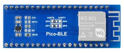
The Pico-BLE is a dual-mode Bluetooth 5.1 expansion module designed for Raspberry Pi Pico, which is controlled via UART AT commands, with SPP and BLE support. Combined with the Raspberry Pi Pico, it can be used for Bluetooth wireless communication applications.
Product parameters
| Category | Parameter |
| BLUETOOTH MODULE | Dual-mode Bluetooth to UART module |
| DIMENSIONS(mm) | 56.5 x 21 |
| TRANSMISSION DISTANCE | 30m (open-air) |
| COMMUNICATION | UART |
| ANTENNA | Onboard PCB antenna |
| INPUT VOLTAGE | 5V/3.3V |
|
OPERATING CURRENT | Startup transient current: about 25mA for about 300ms; Stable status current: about 6mA, nonlow power mode; Low power mode current: refer to user manual |
|
TRANSMISSION CACHE | 1K bytes UART cache, it is recommended to transmit less than 512 bytes per transmission for SPP |
| UART BAUDRATE | 13 different baud rate configuration, 115200 bps by default |
| OPERATING TEMPERATURE | -40℃ ~ 80℃ |
| Function pin | Description |
| VSYS | 3.3V/5V Power |
| GND | GND |
| GP0 | UART transmit pin (default) |
| GP1 | UART transmit pin (default) |
| GP4 | UART transmit pin (default) |
| GP5 | UART transmit pin (default) |
| GP15 | Bluetooth connection status detection pin (high level means Bluetooth is connected) |
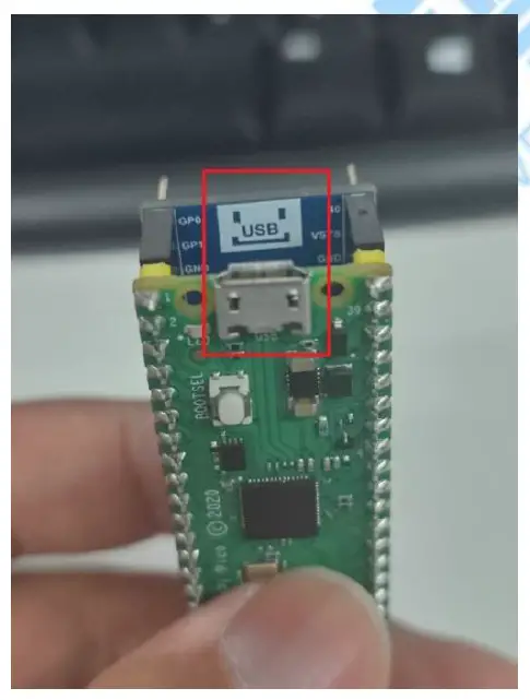
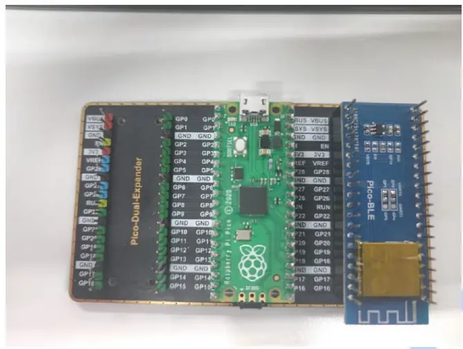
Hardware connection
Direct connection:
Extended version connection:
Product use
Communication format
| Support asynchronous serial communication mode, accept commands sent by the host computer through the serial port Communication Standard:115200 bps — Users can set through serial port commands, see: Module baud rate setting and query Data bits: 8 Stop bits: 1 Parity bits: none Flow control: none Note: The design of all instructions is regular, not randomly divided, you can find the rules by comparing the following | |
| Control command format: AT+<CMD>[<param>]\r\n —- All are characters, not hex numbers | |
| Data Feedback Format::<IND>[<param>]\r\n | |
| Data characteristics | Detailed description |
| AT+ | The control command is the control command given by the control host to the module, starting with “AT+” |
| <CMD> | Followed by <CMD> control, usually 2 characters |
| [<param>] | If there is a parameter after CMD, it is followed by [<param>] |
| \r\n | Finally, it ends with “\r\n”, the character type is linefeed, and windows is the enter key. 0x0D, 0x0A in hex |
| <IND> | 1、Data feedback is that Bluetooth feeds back various status and data information to the host, starting with <IND> |
| A brief introduction to commands | ||
| Functional | Command | Remark |
| Common Command Features | AT+C? | The public command starts with AT+C, followed by “?” is the detailed function command |
| Bluetooth Command Features | AT+B? | The Bluetooth command starts with AT+B, followed by “?” is the detailed function command |
| Public inquiry | AT+Q? | The public query command starts with AT+Q, followed by “?” is the |
| Bluetooth query command | AT+T? | The Bluetooth query command starts with AT+T, followed by “?” is the detailed function command |
Communication command example
| Common Part–Control Instructions–Description | ||
| CMD | Corresponding function | Detailed description |
| AT+CT | Set baud rate | For detail see: Module baud rate setting and query |
| AT+CZ | Chip reset | Chip soft reset, see: Reset and restore factory |
| AT+CW | Chip reset to factory settings | Restore factory settings, clear all previously memorized parameters, see: Module reset and restore factory settings |
| AT+CL | Chip low power settings | See Chip low-power command description, the default is the normal working mode |
| AT+CR | Chip power-on callback information settings | See: Chip power-on callback information setting, the default is open |
| AT+BM | Set BLE Bluetooth name | See: Set the name and address of Bluetooth |
| AT+BN | Set the MAC address of BLE | See: Set the name and address of Bluetooth |
| AT+BD | Set SPP Bluetooth name | See: Set the name and address of Bluetooth |
| AT+QT | Query the baud rate of the | See: Module baud rate setting and query |
| AT+QL | Query the low-power state | See: Set the name and address of Bluetooth |
| AT+TM | Query BLE Bluetooth name | See: Set the name and address of Bluetooth |
| AT+TN | Query BLE Bluetooth | See: Set the name and address of Bluetooth |
| AT+TD | Query SPP Bluetooth name | Seel: Set the name and address of the Bluetooth |
Module baud rate setting and query
| AT+CT??\r\n | Baud rate setting command, ?? represents the serial number of the baud rate | ||||||
| AT+QT\r\n | Baud rate query command, return QT+?? ?? represents the serial number of the baud rate | ||||||
| Baud rate serial number | |||||||
| 01 | 02 | 03 | 04 | 05 | 06 | 07 | |
| 9600 | 19200 | 38400 | 57600 | 115200 | 256000 | 512000 | |
| 08 | 09 | 10 | 11 | 12 | 13 | ||
| 230400 | 460800 | 1000000 | 31250 | 2400 | 4800 | ||
- Once the baud rate is set, the chip will memorize it. The next time you turn it on, the baud rate will be the one you set.
- After setting the baud rate, please wait for 1 second, then send the reset [AT+CZ], or power off.
- If you want to restore the default baud rate, please send the command to restore the factory settings, then the chip will automatically erase all configurations.
Module reset and factory reset
Reset command: AT+CZ\r\n
Please wait one second after entering the reset command
Factory reset command: AT+CW\r\n
Please wait five seconds after entering the factory reset command
Set the name and address of the Bluetooth
| AT+BMBLE-Waveshare\r\n | Set BLE Bluetooth name to “BLE-Waveshare” |
| AT+BN112233445566\r\n | Set the address of BLE. The address displayed on the mobile phone is: 66 55 44 33 22 11 |
| AT+BDSPP-Waveshare\r\n | Set the SPP Bluetooth name to “SPP-Waveshare” |
- After setting the Bluetooth name, please reset the module, and use the mobile phone to search again after reset.
- The maximum length of the Bluetooth name is 30 bytes
- After modifying the Bluetooth name, if the device name displayed on the mobile phone does not change, the main reason may be that you have not modified the Bluetooth address, resulting in the mobile phone not being updated synchronously. At this time, what you need to do is to change the pairing information on the mobile phone. Delete and search again, or search with another device.
Query the name and address of Bluetooth
| AT+TM\r\n | Return TM+BLE-Waveshare\r\n for Bluetooth name BLE-Waveshare |
| AT+TN\r\n | Returns the Bluetooth address of TN+12345678AABB\r\n BLE: 0xBB, 0xAA, 0x78, 0x56, 0x34, 0x12 |
| AT+TD\r\n | Return to TD+SPP-Waveshare\r\n for Bluetooth name SPP-Waveshare |
There is no SPP address whether it is set or queried, because the SPP address is obtained by +1 on the
highest byte of the BLE MAC address, for example:
The address of BLE is returned as: TN+32F441F495F1,
This means the address of BLE is: 0xF1 , 0x95 , 0xF4 , 0x 41 , 0xF4 , 0x32
Then the address of SPP is: 0xF2 , 0x95 , 0xF4 , 0x 41 , 0xF4 , 0x32
Chip low power instruction description
| AT+CL00\r\n | Do not enter low power mode. It will be valid at the next power-on. Be careful to restart the power after setting |
| AT+CL01\r\n | Enter low power mode. It is valid at the next power-on. After setting, pay attention to power on again — the chip enters this state by default, no need to set |
| AT+QL\r\n | Low-power query command. The return value is QL+01\r\n, indicating that the current working state is low power consumption mode |
- After setting, you need to power on again to update the configuration
- This command is memorized. After the command is sent successfully, the chip will save it.
- After starting the low-power mode, there are many restrictions, which are generally turned off by default.
- After the setting, the chip will return to the device information normally when it is powered on. AT commands can be set within 5 seconds, and after 5 seconds, any AT commands will be ignored before the Bluetooth connection.
- The difference between low power consumption and normal operation is mainly due to the difference in the way of Bluetooth broadcasts when Bluetooth is not connected. During normal operation, Bluetooth is always in the broadcasting state. During low power consumption, it broadcasts every 0.5 seconds, once every 0.1 seconds, and the rest of the time is in a sleep state. When connected to Bluetooth, the power consumption of the two working modes is similar (of course,
the low power consumption will be a little lower),If it is not particularly sensitive to power consumption or it will be in a disconnected state for a long time after power-on, it is better to keep the module in a normal working state. - The following table is the current under each working state, which is measured in the experimental environment, and the results are for reference only.
| Serial number | Current | Description | |
|
AT+CL00\r\n
Low power working mode |
Boot moment |
12mA | When the chip is powered on, the peripherals need to be initialized. The instantaneous current is relatively large, and this time is maintained for 300ms, and it enters a low-power state. |
|
Working Status – Not Connected |
1mA, 5mA alternately | The chip is in normal working state, broadcasts normally, and is in a periodic state of sleep, wake-up broadcast, and sleep. The purpose is to save power consumption, the cycle is 500ms. 100ms broadcast once, 400ms sleep | |
| Working status – to connect | 6mA | When the connection is successful, the chip will no longer go to sleep. but at work | |
|
AT+CL01\r\n
normal working mode |
Boot moment |
25mA | When the chip is powered on, the peripherals need to be initialized. The instantaneous current is relatively large, this time is maintained for 300ms, and it enters the 5mA working state |
| Whether connected or not | 6.5mA | The chip is always working. Small fluctuations in current, negligible |
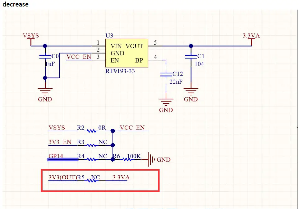
If you feel that the above power consumption is relatively high, you can use 3.3V to directly supply power to the module and the current will further
decrease
Chip BLE enable and SPP enables
| AT+B401\r\n | Enable BLE function. Of course AT+B400\r\n is closed |
| AT+B500\r\n | Disable the function of SPP. Of course AT+B501\r\n is turned on |
| AT+T4\r\n | Check whether the BLE function is enabled. The chip will return T4+01 or T4+00 |
| AT+T5\r\n | Check whether the SPP function is enabled. The chip will return T5+01 or T5+00 |
- After the BLE/SPP function is turned off, it must be powered on again for this function to take effect. Of course it’s the same
- You only need to set it once, the chip automatically saves the parameters, and you don’t need to set it next time
- After the BLE/SPP function is turned off, the mobile phone cannot search for the name of BLE.
Description of the error message returned by the chip
| ER+1\r\n | The received data frame is incorrect |
| ER+2\r\n | The received command does not exist, that is, the string like AT+KK you sent cannot be |
| found | |
| ER+3\r\n | The received AT command did not receive a carriage return and line feed, that is, \r\n |
| ER+4\r\n | The parameter sent by the command is out of range, or the command format is incorrect. Please check your AT commands |
| ER+7\r\n | The MCU sends data to the mobile phone, but the mobile phone does not open notify. In the successful state of BLE connection |
Focus on the description of notify [monitoring]. After the test APP on the mobile phone is connected to the Bluetooth chip, notify must be turned on. The bluetooth chip can
send data to the mobile phone. When the mobile phone sends data to the Bluetooth chip,it is enough to use the write feature.
Chip power-on callback information settings
| AT+CR00\r\n | Turn off postback messages for power-on. Be careful to restart the power after setting |
| AT+CR01\r\n | Enable the return message of chip power-on. It is valid at the next power-on. Be careful to restart the power after setting |
Note: After this function is turned off, it will also turn off the OK or ER+X return information that is actively returned after the AT command is executed. It is recommended to keep it turned on here.
Transparent transmission description
- After the Bluetooth connection, the module automatically enters the transparent transmission mode. Except for the completely correct AT command, the rest of the data will be transparently transmitted.
- The maximum amount of data that can be handled in a single time is 1024 bytes. SPP recommends that it should not exceed 512 bytes at a time.
- The MTU (maximum communication packet length) of the mobile phone APP generally defaults to 20 bytes for 1 data packet; when the data packet sent by the module exceeds 20 bytes, the module will automatically divide the packet according to the set MTU; you can Modify the MTU to modify the data interaction speed (the larger the
MTU, the faster the data interaction speed).


 Module User Manual")


