![]()
User manual 
PRECAUTIONS AND SAFETY MEASURES
The adapter has been designed in compliance with IEC/EN61010-1 guidelines relevant to electronic measuring adapters. For your safety and in order to prevent damaging the
adapter, please strictly follow the procedures described in this manual and read carefully all notes preceded by symbol. ![]() Before and after carrying out measurements, observe
Before and after carrying out measurements, observe
the following instructions:
- Do not carry out any measurements in humid environments.
- Do not carry out any measurements in case gas, explosive materials or flammables are present, or in dusty environments.
- Avoid any contact with the circuit under test if no measurement is in progress.
- Avoid any contact with exposed metal parts, unused measuring probes, circuits, etc.
- Do not carry out any measurement in case you find anomalies in the adapter such as deformation, breaks, substance leaks, absence of display on the screen, etc.
- Pay special attention when measuring voltages higher than 25V AC, since the risk of electrical shock exists.
In this manual, and on the adapter, the following symbols are used:
| Warning: observe the instructions given in this manual; improper use could damage the adapter or its components. | |
 | Adapter with double insulation |
| AC Voltage | |
 | Ground reference |
1.1 PRELIMINARY INSTRUCTION
![]() CAUTION
CAUTION
- The adapter can be used for AC VOLTAGE measurements on installations with CAT III 300V to ground
- Do not use the adapter on loads with technical specifications different by the same described in § 7
- Do not use the adapter if the protection conditions on the circuit are limited or protection devices are damaged.
- Do not use the adapter in circuits with voltages and currents higher than the rated ones
- Do not carry out any measurement in case you find anomalies in the adapter such as deformation, breaks, substance leaks, absence of display on the screen, etc.
GENERAL DESCRIPTION
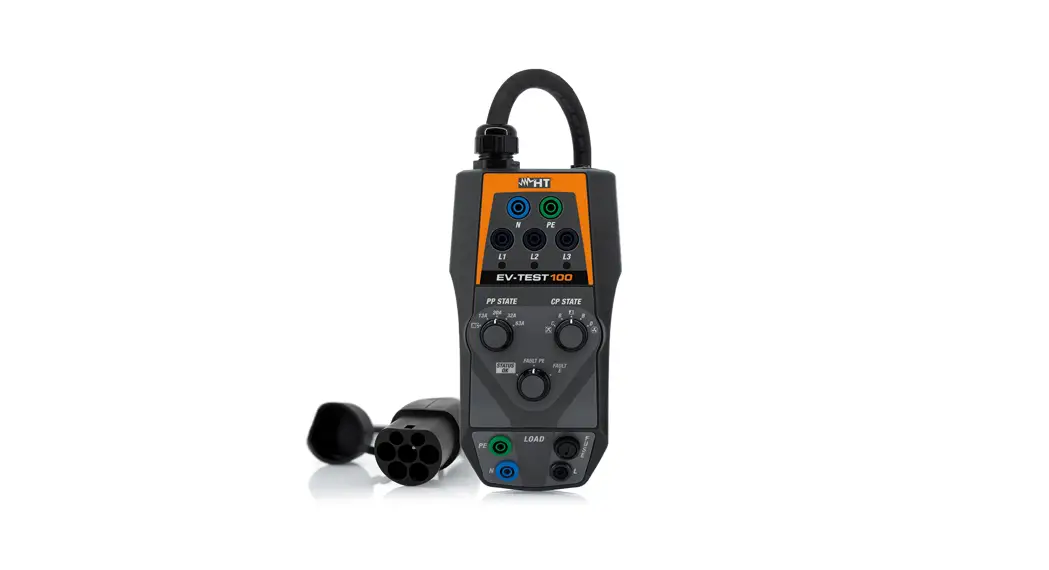
The EV-TEST100 model is an adapter designed to interface with the electric car charging stations’ sockets (EVSE – Electrical Vehicle Supply Equipment) and perform electrical
safety tests on these devices. The adapter is capable of simulating the presence of an electric vehicle in order to measure the output voltage signals from the charging stations
as well as fault conditions.
EV-TEST100 can be used in combination with the following HT safety testers:
| Model (*) | Construction category | FW version |
| MACROTESTEV | CAT IV 300V | 2.00 (or higher) |
| COMBIG2 | ||
| COMBIG3 | ||
| COMBIG2PLUS | ||
| COMBITEST425EV | ||
| MT-300 |
(*) The list of available models can be changed without notice. In case of doubt contact the after-sales service
The adapter has the following features:
- Use for EVSE stations with charging modes 2 and 3
- Test cable with Type 2 connectors (IEC 62196-2)
- Vehicle simulation via Control Pilot system (CP state)
- Cable current capacity simulation via Proximity Pilot system (PP state)
- Fault PE simulation condition
- Fault condition simulation on the Control Pilot (Fault E)
- Efficiency check of internal station energy meter (LOAD section)
- LED indications for system phase detection
- Terminals for connection to HT tester
- Protection fuse on LOAD section
- Test in compliance with IEC/EN61851-1 and IEC/EN60364-7-722 guidelines
PREPARATION FOR USE
3.1 INITIAL CHECKS
Before shipping, the adapter has been checked from an electric as well as a mechanical point of view. All possible precautions have been taken so that the adapter is delivered free of damage. However, a thorough check of the adapter is recommended in order to detect any damage suffered during transport. In case anomalies are found, immediately
contact the forwarding agent. Also, check whether the packaging contains all parts indicated in § 7.1.1. In case of discrepancy, please contact the Dealer. Should the adapter be returned, please follow the instructions given in § 8.
![]() CAUTION
CAUTION
Should the adapter be used differently from what is specified by the manufacturer, the protection provided may be impaired
3.2 ADAPTER POWER SUPPLY
The adapter is powered directly by the charging station via an integrated plug cable.
3.3 STORAGE
In order to guarantee accurate measurement, after a long storage time, wait for the adapter to come back to normal condition (see § 7).
NOMENCLATURE
4.1 DESCRIPTION OF THE ADAPTER
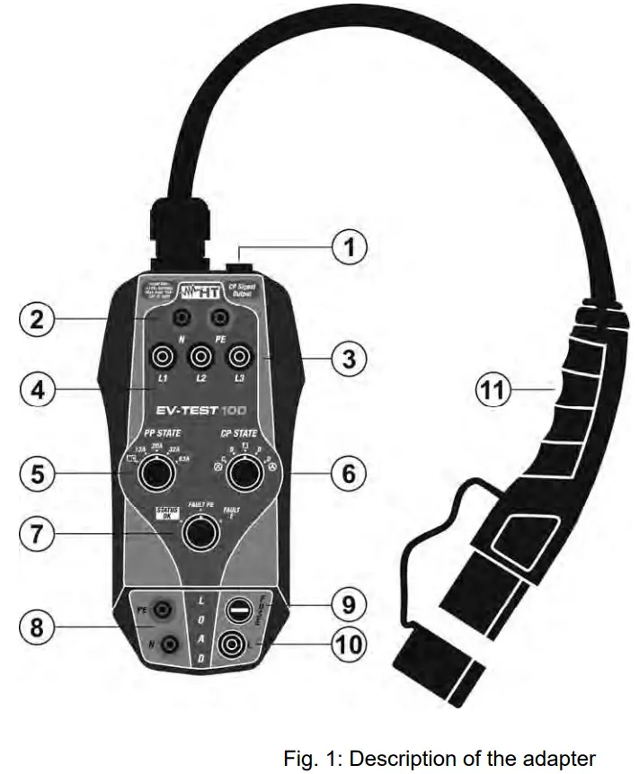
CAPTION:
- Input for connection to HT instrument via C100EV cable
- Terminals N, PE for connection to HT instrument
- Terminals L1, L2, L3 for connection to HT instrument
- LED for phase presence detection
- PP state selector
- CP state selector
- FAULT PE, FAULT E function selector
- N, PE terminals for external load connection
- LOAD section protection fuse
- Terminal L for external load connection
- Type 2 plug cable for connection to EVSE
4.2 FUNCTION DESCRIPTION OF PP STATE SELECTOR
| Position | Description |
| NC | EVSE disconnected |
| 13A | EVSE connected with a maximum current of 13A |
| 20A | EVSE connected with a maximum current of 20A |
| 32A | EVSE connected with a maximum current of 32A |
| 63A | EVSE connected with a maximum current of 63A |
4.3 FUNCTION DESCRIPTION OF CP STATE SELECTOR
| Position | Description |
| A | Electric vehicle disconnected |
| B | Electric vehicle connected, not ready for charging |
| C | Electric vehicle connected, ready for charging, ventilation not required |
| D | Electric vehicle connected, ready for charging, ventilation required |
4.4 FUNCTION DESCRIPTION OF FAULT SELECTOR
| Position | Description |
| STATUS OK | No-fault simulation |
| FAULT PE | Fault condition simulation on PE protective conductor (EVSE does not recharge) |
| FAULT E | Fault condition simulation on the Control Pilot (EVSE does not recharge) |
OPERATING INSTRUCTIONS
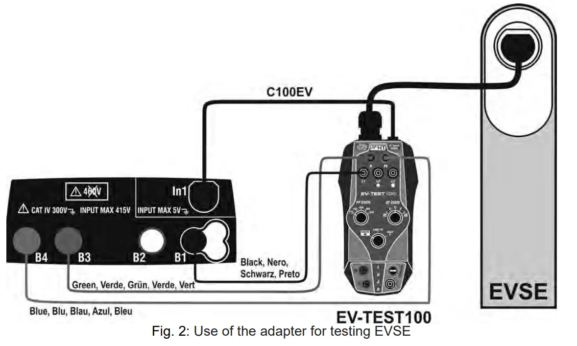
5.1 TEST ON EVE
- Connect the adapter to the In1 input of the HT multifunction instrument using the C100EV supplied cable (see Fig. 1 – part1)
- Connect the L1, PE, and N terminals (see Fig. 1 – parts 2, 3, and 4) of the adapter respectively to B1, B3, and B4 inputs of the HT multifunction tester by using the cables
supplied together - Connect the Type 2 plug cable (see Fig. 1 – part 11) to the EVSE
- Move the PP STATE selector (see Fig. 1 – part 5) to the NC position
- Move the CP STATE selector (see Fig. 1 – part 6) to the A position
- Move the FAULT selector (see Fig. 1 – part 7) to the STATUS OK position
- Select the “EVSE Test” mode on the HT multifunction tester
- Press the GO/STOP button on the HT multifunction tester and follow the guided test procedure (see the related user manual)
![]() CAUTION
CAUTION
For detailed instructions on the use of the adapter, refer to the user manual of the HT tester to which it must be connected
5.2 EFFICIENCY CHECK OF EVSE ENERGY METER
The adapter allows performing a test in order to evaluate the efficiency of the energy meter inside the EVSE. Consider the following steps:
- Connect an external load with max absorbed current 10A AC to the input terminals L, N, PE (see Fig. 1 – parts 8 and 10) of LOAD section
- Set the three switches to the positions: STATUS OK, C or D (CP STATE), and 13A, 20A, 32A, or 63A (PP STATE)
- Refer to the instructions of the EVSE under test for the energy meter reading.
MAINTENANCE
![]() CAUTION
CAUTION
- Only skilled and trained technicians should perform maintenance operations. Before carrying out maintenance operations, disconnect all cables from the input terminals.
- Do not use the adapter in environments with high humidity levels or high temperatures
6.1 CLEANING THE ADAPTER
Use a soft and dry cloth to clean the adapter. Never use wet cloths, solvents, water, etc.
6.2 END OF LIFE
CAUTION: the symbol on the adapter indicates that the appliance and its accessories must be collected separately and correctly disposed of.
TECHNICAL SPECIFICATIONS
| Input voltage: Connection to EVSE: Recharging stations: PP Simulation: CP Simulation: Simulation EVSE fault: CP output signal: Allowed output load: Protection fuse: Safety: Reference guidelines: Insulation: Measurement category: Pollution degree: Dimensions (L x W x H): Weight (with integrated cable): Mechanical protection: Working temperature: Working humidity: Storage temperature: Storage humidity: Max operating altitude: | max 415V AC Phase-Phase, 50/60Hz ±5% integrated cable with Type 2 plug, length 60cm charging modes 2 and 3 NC,13A, 20A, 32A, 63A status A, B, C, D, ventilation/not ventilation Fault PE, Fault E PWM communication protocol, 12V 240V, 50/60Hz, max 10A AC Fast type 250V/10A (5x20mm) (0.2×0.8in) IEC/EN61010-1 IEC/EN61851-1, IEC/EN60364-7-722 double insulation CAT III 300V 2 210 x 115 x 60mm (8 x 5 x 2in) 900g (32ounces) IP40 0°C ÷ 40°C (32°F ÷ 104°F) <80%RH -10°C ÷ 60°C (14°F ÷ 140°F) <80%RH 2000m (6562ft) |
This adapter complies with the requirements of the Low Voltage Directive 2014/35/EU (LVD) This adapter complies with the requirements of European Directive 2011/65/EU (RoHS) and 2012/19/EU (WEEE)
7.1 ACCESSORIES
7.1.1 Accessories provided
- Cable for connection to HT tester
- Carrying case
- User manual
ASSISTANCE
8.1 WARRANTY CONDITIONS
This adapter is warranted against any material or manufacturing defect, in compliance with the general sales conditions. During the warranty period, defective parts may be replaced. However, the manufacturer reserves the right to repair or replace the product. Should the adapter be returned to the After-sales Service or to a Dealer, transport will be at the Customer’s charge. However, shipment will be agreed upon in advance. A report will always be enclosed in a shipment, stating the reasons for the product’s return. Only use the original packaging for shipment. Any damage due to the use of non-original packaging material will be charged to the Customer. The manufacturer declines any responsibility for injury to people or damage to property.
The warranty shall not apply in the following cases:
- Repair and/or replacement of accessories and battery (not covered by warranty).
- Repairs that may become necessary as a consequence of incorrect use of the adapter or due to its use together with non-compatible appliances.
- Repairs that may become necessary as a consequence of improper packaging.
- Repairs may become necessary as a consequence of interventions performed by unauthorized personnel.
- Modifications to the adapter were performed without the manufacturer’s explicit authorization.
- Use not provided for in the adapter’s specifications or in the instruction manual.
The content of this manual cannot be reproduced in any form without the manufacturer’s authorization.
Our products are patented and our trademarks are registered. The manufacturer reserves the right to make changes in the specifications and prices if required by
improvements in technology.
8.2 ASSISTANCE
If the adapter does not operate properly, before contacting the After-sales Service, please check the conditions. Should the adapter still operate improperly, check that the product is operated according to the instructions given in this manual. Should the adapter be returned to the After-sales Service or to a Dealer, transport will be at the Customer’s charge. However, shipment will be agreed upon in advance. A report will always be enclosed in a shipment, stating the reasons for the product’s return. Only use the original packaging for shipment. Any damage due to the use of non-original packaging material will be charged to the Customer.


