NTI ST-IPFOHD-LC-ULC Low-Cost HDMI Extender Over IP Via One LC Singlemode-Multimode Fiber Optic Cable User Manual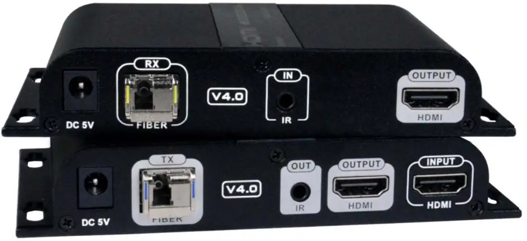
TRADEMARK
XTENDEX and the NTI logo are registered trademarks of Network Technologies Inc in the U.S. and other countries. All other brand names and trademarks or registered trademarks are the property of their respective owners.
COPYRIGHT
Copyright © 2021 by Network Technologies Inc. All rights reserved. No part of this publication may be reproduced, stored in a retrieval system, or transmitted, in any form or by any means, electronic, mechanical, photocopying, recording, or otherwise, without the prior written consent of Network Technologies Inc, 1275 DannerDrive, Aurora, Ohio 44202.
CHANGES
The material in this guide is for information only and is subject to change without notice. Network Technologies Inc reserves the right to make changes in the product design without reservation and without notification to its users.
INTRODUCTION
INTRODUCTION
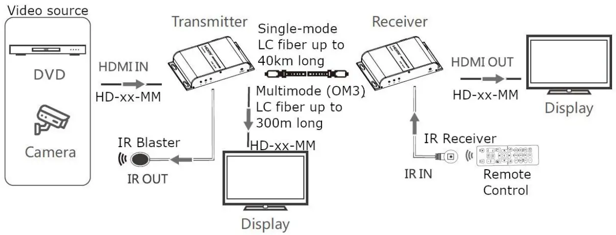
The XTENDEX® HDMI Extender Over IP via Fiber Optic Cable transmits HDMI video, embedded audio, and IR signals up to 24.8 miles (40 kilometers) away from an HDMI source using a single LC singlemode fiber optic strand or 984 feet (300 meters) using OM3 LC multimode fiber optic cable.
Each HDMI Extender Over IP consists of a local unit that connects to an HDMI source and provides a buffered HDMI input loopthrough, and a remote unit that connects to an HDMI display. The local and remote units can be connected together for a Point-toPoint connection via Fiber Optic Cable or a Point-to-Many connection via a network switch. Support for multiple transmitters requires a managed network switch.
- Signal transmission via single-strand LC fiber optic cable.
- Using singlemode 9-micron cable, extend to 24.8 miles (40 km).
- Using 50-micron OM3 (or better)multimode cable, extend to 984 feet (300 meters).
- Supports HDTV resolutions to 1080p.
- Cascade network switches to extend the length longer distances.
- Up to three switches can be cascaded.
- HDMI features supported:
- HDMI 1.3
- 36-bit Deep Color
- RGB, YCbCr 4:4:4, and YCbCr 4:2:2
- LPCM
- Bandwidth up to 4.46Gbps
- HDCP 1.4 compliant.
- Full Infrared Remote (IR) control of HDMI source from remote HDTV using existing source remote control.
- For a point-to-many connection, a standalone network with an unmanaged SFP network switch, hub, or router can be used instead of a managed SFP network switch.
- Easily expandable. Add remote units as you add monitors.
- Up to 253 receivers supported.
- Easily expandable. Add remote units as you add monitors.
- It is not recommended to use any other network devices on this standalone network as it may cause degradation in performance.
- Support for multiple transmitters (many-to-many connection) requires a managed SFP switch with VLAN support. Standard LAN switches can only support one transmitter.
- The managed SFP switch must support port-based IEEE 802.1Q VLAN.
- Each VLAN acts as a separate HDMI Over IP Channel on the network.
- Each VLAN channel supports one transmitter.
- Number of local and remote units that can be used is dependent on the backplane bandwidth of the switch.
- Plug-and-Play installation allows receivers to find the transmitters automatically on the same subnet.
- Local and remote units must be in the same LAN. The units do not support WAN connections.
- Low RFI/EMI for sensitive applications.
- Built-in default EDID table.
- Cables can be installed in conduit prior to extender installation.
- Integrated mounting brackets for easy surface/wall mounting.
MATERIALS
Materials supplied with this kit:
1– ST-IPFOHD-R-LC-ULC Receiver
2– 100-240VAC @50/60Hz ; 5VDC 2A Output (for US) / 5VDC/3A (for EU, UK and AUS)
1– T1550/R1310nm 1000 Base-T Gigabit SFP module
1– T1310/R1550nm 1000 Base-T Gigabit SFP module
1– IR Emitter Extension Cable
1– IR Receiver Extension Cable
URL Slip with path to this manual
Requirements:
- Source device with HDMI output port (computer graphics card,DVD, PS3, HD monitor equipment etc.)
- Display device with HDMI input port (HDTV, projector).
- HDMI cable and LC optical fiber cable.
Cables
- Use a simplex LC singlemode 9-micron fiber optic cable to extend the receiver from the transmitter up to 24.8 miles (40 km).
- Use FIBER-AD-SS-SCFLCM to convert a male simplex SC singlemode connector to a male simplex LC singlemode connector.
- Use a simplex LC multimode 50-micron OM3 (or better)fiber optic cable to extend the receiver from the transmitter up to 984 feet (300 meters).
- Use HD-xx-MM cables to connect an HDMI source or display up to 50 feet.
- Use DP-HD-xx-MM cables to connect a DisplayPort source up to 15 feet.
- Use DVI-HD-xM-MM cables to connect a DVI source up to 5 meters.
- Use USB3C-HD4K-xx-MM to connect a USB-C or Thunderbolt 3 device up to 10 feet.
- Cables are not included.
CONNECTORS AND LEDS
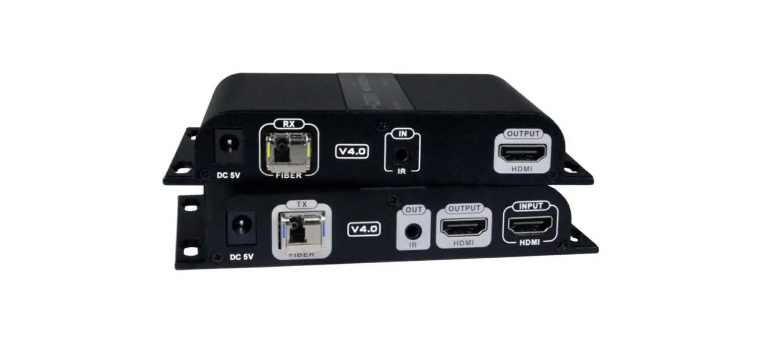
ST-IPFOHD-L-LC-ULC Transmitter (Local Unit)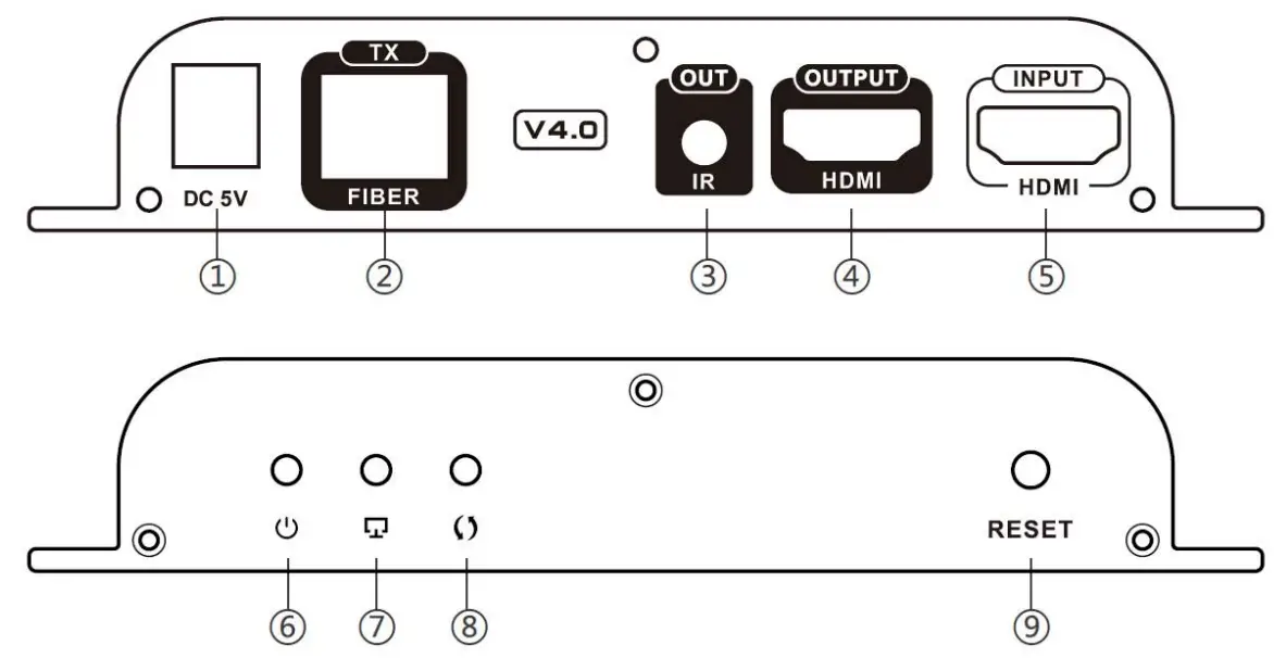
| # | LABEL | CONNECTOR/LED | DESCRIPTION |
| 1 | DC 5V | 2.1×5.5mm Power Jack | for connection of power supply |
| 2 | TX- FIBER | SFP Socket | For insertion of the T1310/R1550nm Transceiver (To connect the LC fiber cable from the Receiver) |
| 3 | IR OUT | 3.5mm Female Jack | For connection of the IR Blaster cable |
| 4 | HDMI OUTPUT | Female HDMI Connector | For the HDMI cable from a local display |
| 5 | HDMI INPUT | Female HDMI Connector | For the HDMI cable from the video source |
| 6 | Power Symbol | Blue LED | Indicates the Transmitter is powered ON |
| 7 | Display Symbol | Green LED | Flashes to indicate a connection with the Receiver |
| 8 | Arrows | Green LED | Illuminates steady ON when there is data transmission between the Transmitter and Receiver |
| 9 | Reset | Button | Press to restart the Transmitter |
ST-IPFOHD-R-LC-ULC Receiver (Remote Unit)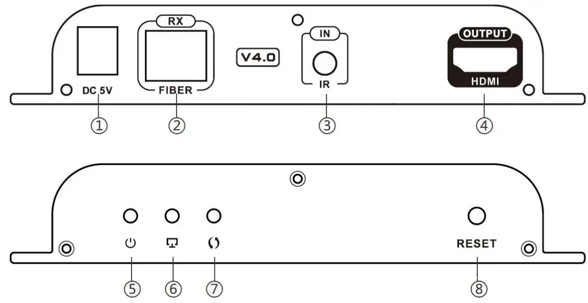
| # | LABEL | CONNECTOR/LED | DESCRIPTION |
| 1 | DC 5V | 2.1×5.5mm Power Jack | for connection of power supply |
| 2 | RX- FIBER | SFP Socket | For insertion of the T1550/R1310 Transceiver (To connect the LC fiber cable from the Transmitter) |
| 3 | IR OUT | 3.5mm Female Jack | For connection of the IR Receiver cable |
| 4 | HDMI OUTPUT | Female HDMI Connector | For the HDMI cable from an extended display |
| 5 | Power Symbol | Blue LED | Indicates the Receiver is powered ON |
| 6 | Display Symbol | Green LED | Flashes to indicate a connection with the Receiver |
| 7 | Arrows | Green LED | Illuminates steady ON when there is data transmission between the Transmitter and Receiver |
| 8 | Reset | Button | Press to restart the Receiver |
CONNECTION
- Connect an HD-xx-MM cable (xx = 3,6,10,15,20,30 and 50 feet- sold separately) between the Transmitter “HDMI IN” port and the Video Source (Computer, Camera, DVD player, etc.) and another between the Receiver “HDMI OUT” port and the HDMI- display device. Optionally, connect a third HD-xx-MM cable between a local display and the “HDMI OUT” port on the Transmitter.
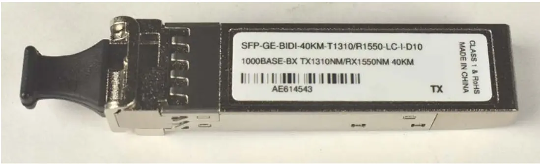
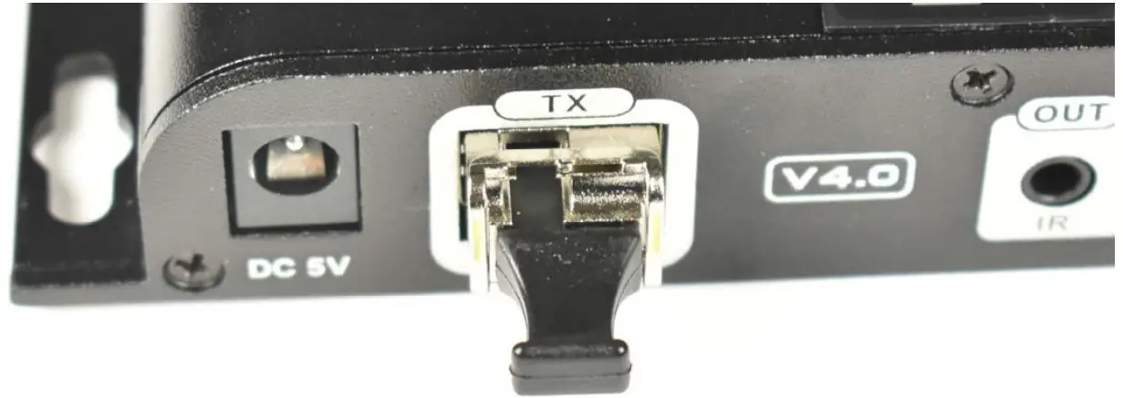
- Plug the T1310/R1550 Transceiver into the “Fiber-TX” port on the ST IPFOHD-L-LC-ULC Transmitter.
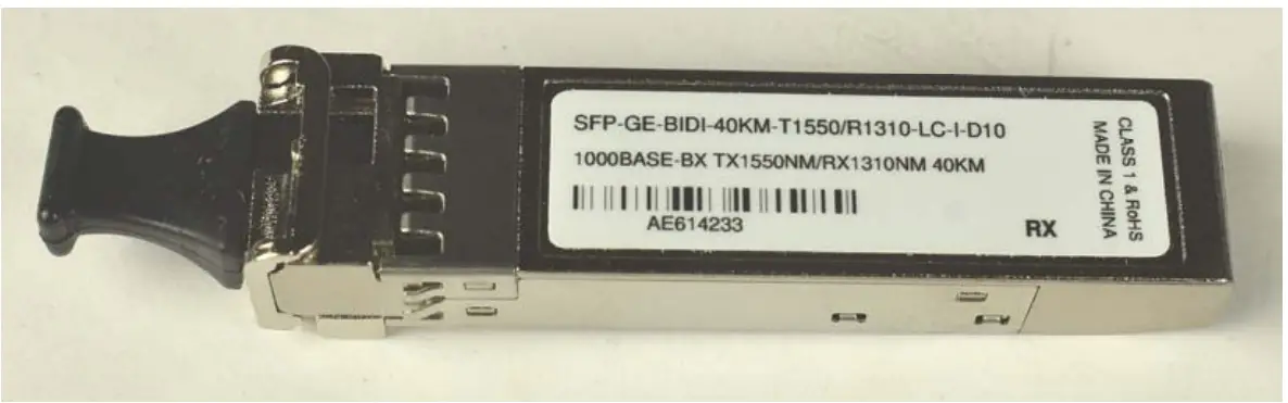
- Plug the T1550/R1310 Transceiver into the “Fiber-RX” port on the ST IPFOHD-R-LC-ULC Receiver.
- Connect a simplex single-mode LC fiber optic cable up to 40km in length (or multimode (OM3) cable up to 300m in length) between the Transmitter SFP transceiver and the Receiver SFP transceiver.
- Plug the 5VDC power supplies into the “DC 5V” jacks on the Transmitter and Receiver and connect them to power.

If an SFP Optical Transceiver should ever need replacement, use a universal transceiver with a transmission rate of 1.25 Gbps. Contact an NTI Sales Associate for assistance at 330-562-7070.
Transceiver Installation
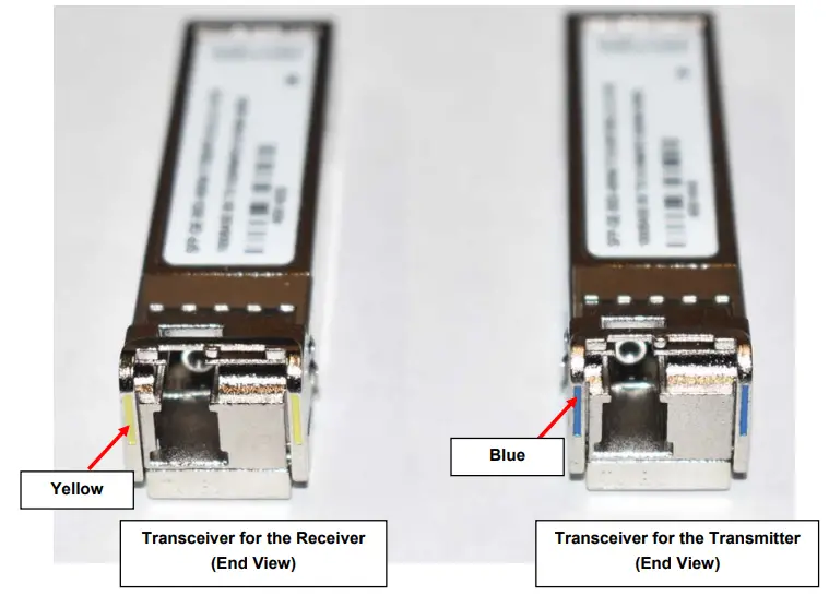
The transceivers need to be fully inserted in order to function. Follow these steps for proper installation.
- Identify which transceiver is being installed. The T1310/R1550 (blue) transceiver goes in the Transmitter. The T1550/R1310 (yellow) transceiver goes in the Receiver.
Transceiver for the Transmitter (Top View)
Transceiver for the Receiver (Top View)

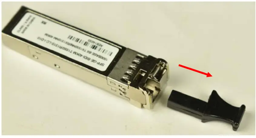
- Remove the dust cover from the Transceiver and set to the side.

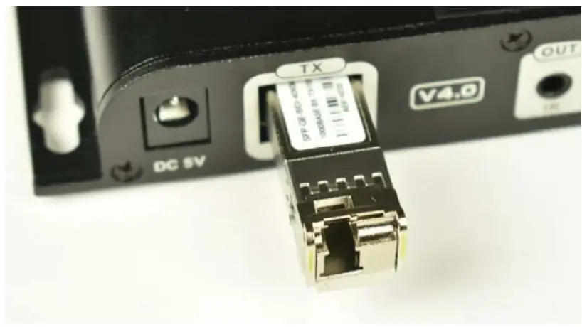
- Insert the Transceiver part way into the SFP opening in the extender.

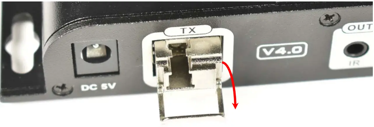
- Fold the latch down and press the Transceiver into the opening until fully seated.

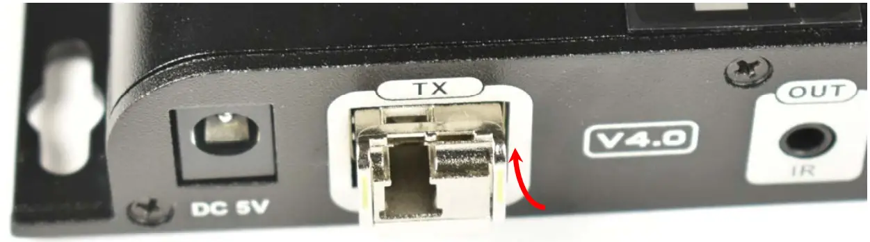
- Rotate the latch back up to lock the Transceiver into position.

- If not installing the fiber optic cable, return the dust cover to the Transceiver.

IR Control
To make use of a video source that can be operated with a remote control, connect the IR blaster and Receiver cables as follow.
- Connect the IR Receiver to the “IR IN” port on the ST-IPFOHD-R-LC ULC Receiver. Locate the receiver such that you can see it when using the remote control.
- Connect the IR Blaster to the “IR OUT” port on the ST-IPFOHD-L-LC ULC Transmitter. Locate the blaster as close to the IR Input window as practical on the video source.
One to Many Connection
A Transmitter can be connected to a 1 Gigabit Fiber Optic SFP Switch for a connection to multiple Receivers. Each connected Receiver will receive the same video signal from the Transmitter. The Transmitter and Receivers must be connected to the same VLAN group in order for this to work. You can have only one Transmitter in a VLAN group.
To use an SFP switch, a T1550/R1310 Transceiver (sold separately) will need to be installed in the SFP Switch where the Transmitter connects to it. A T1310/R1550 Transceiver (sold separately) will need to be installed in the SFP Switch where each Receiver connects to it. For additional Transceivers, contact an NTI Sales Associate at 330-562-7070.
Each simplex single-mode LC fiber cable used to connect to the switch can be up to 40km in length.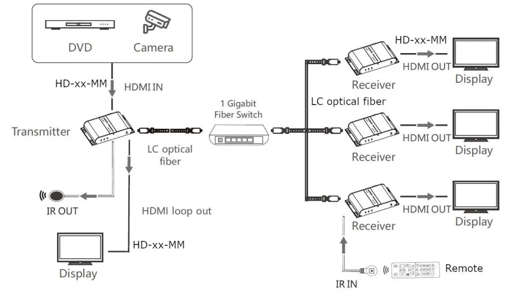
Many-to Many Connection
Support for multiple transmitters requires a managed network switch with VLAN support. Standard LAN switches can only support one Transmitter.
The managed network switch must support port-based IEEE 802.1Q VLAN.
Each VLAN acts as a separate HDMI Over IP Channel on the network. Each VLAN channel supports one Transmitter.
Cascading Switches
Ethernet switches can be cascaded, but no more than 3 switches per application.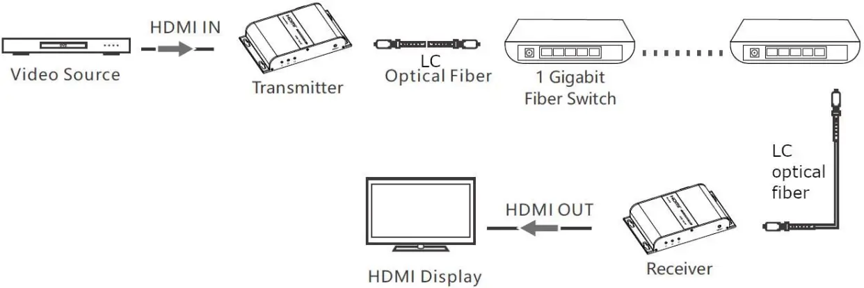
Technical Specification
| HDMI Version | HDMI 1.3 |
| HDCP supported | HDCP 1.4 |
| Supported Resolutions | 640×480@59/60Hz (480p),720×480@59/60Hz (480p),720×576@50/59/60Hz (576p),800×600@60Hz, 1024×768@60Hz,1280×720@50/59/60Hz (720p),1280×960@60Hz,1280×1024@60Hz,1366×768@60Hz,1440×900@60Hz,1600×900@60Hz,1680×1050@60Hz,1920×1080@23/24/25/29/30/50/59/60Hz (1080i/1080p) |
| DDC signal voltage | 5Vp-p (TTL) |
| Audio format | LPCM |
| Center wavelength | 1310/1550nm |
| Fiber Connector Type | LC |
| Local Unit Ports |
|
| Remote Unit Ports |
|
| Transmission rate | 1,25Gbps |
| Output light power | ±3dB |
| Input light power | ±3dB |
| Receive sensitivity | ≤-3dBm |
| Return loss | 12dBm |
| IR Remote Control | Frequency range: 20~60KHz |
| Protection Level | Implementation of the standard: IEC61000-4-2·
|
| Operating temperature | -4 to 140°F (-20˚C ~ 60˚C) |
| Storage temperature | -22 to 158°F (-30˚C ~ 70˚C) |
| Relative humidity | 0~90%RH Non-condensing |
| Max. Distance |
|
| Chassis material | Aluminum alloy |
| Power Supply- Local and Remote Unit | Input: 100-240VAC @50/60Hz ;Output: 5VDC 2A (US) / 5VDC 3A (UK, EU, AUS) |
| Size WxDxH | 5.43 x 3.21 x 0.94 in (138.00 x 82 x 24.00 mm) |
| Approvals | CE, RoHS, FCC |
WARRANTY INFORMATION
The warranty period on this product (parts and labor) is two (2) years from the date of purchase. Please contact Network Technologies Inc at (800) 742-8324 (800-RGB-TECH) or (330) 562-7070 or visit our website at http://www.networktechinc.com for information regarding repairs and/or returns. A return authorization number is required for all repairs/returns.