SENSECAP pH Sensor (S-pH-01) User Guide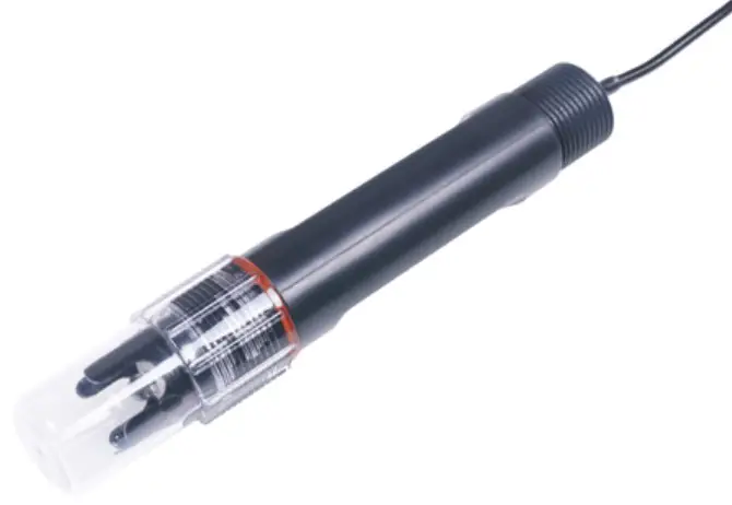
Introduction
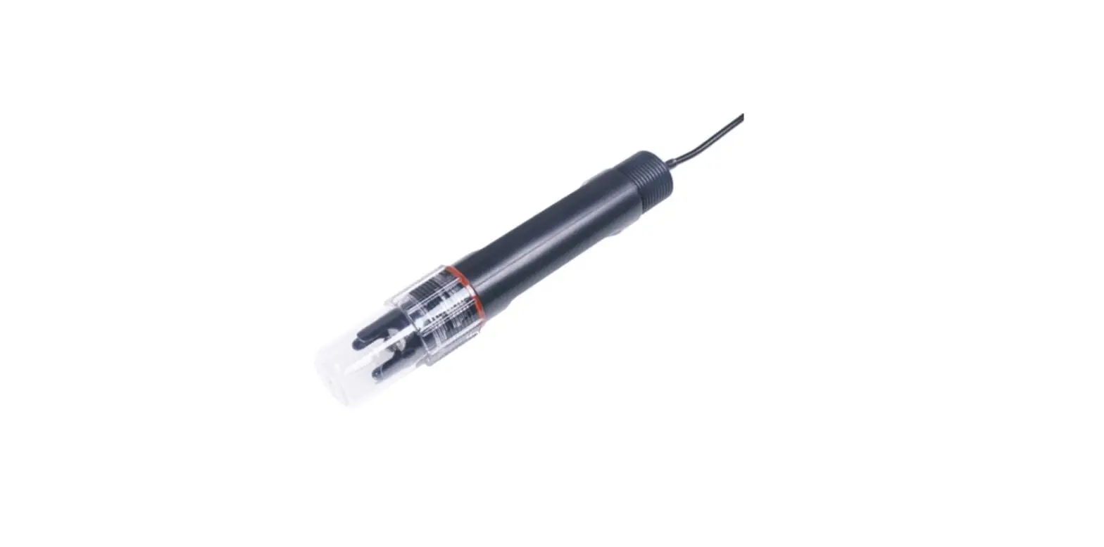
S-PH-01 transmitter measures the PH of solution or semi-solid substrate. The output signal canbeRS485and Analog Voltage. The sensor is applicable for industrial, water processing, sewerage system, irrigation, smart agriculture etc.
- Can be used for PH measurement
- Output Interface with RS485, Voltage
- High impedance and isolated electrode input
- High accuracy with excellent stability
- Reverse power protection and Built-in TVS/ESD protection
| Specificatio ns | ||
| Output Interface | Analog Voltage 0-2V(Output resistance ~0ohm) | RS485 Modbus-RTU |
| Power Supply | 3.9-30V/DC | 3.9-30V/DC |
| Power Consumption | 35mA@24V DC | 35mA@24V DC |
| Start-up time | < 2 seconds | |
| PH Measurement | High impedance and isolated input; Range: 0-14PH, Resolution: 0.01PH,Accuracy: +/-0.1PH; Can be used for solution or semi-solid substrate | |
| Temperature Measurement(Option) | Range: -40~80°C, Resolution: 0.1°C, Accuracy: +/-0.5°C | |
| IP Ratings | Electrode: IP68; Transmitter: IP65 | |
| Operating Temperature | -40~85°C | |
| Installation | Electrode: 3/4″NPT screw threads; Transmitter: Mounting hole | |
| Cable Length | Power and Signal Cable:2 meters or Customize; Electrode Cable: 5 meters | |
| Dimension | Electrode: Width*Diameter 160*30mm; 3/4″NPT screw threads Transmitter: 140mm*65mm*50mm | |
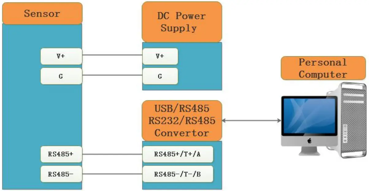
Wiring diagrams
| Type | Wiring diagram |
| Analo g Voltag e Outpu t | Red (V+): Power Supply + Black (G): Power Supply – Blue (O1): Analog Output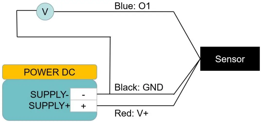 |
| RS485Modbus | Red (V+): Power Supply + Black (G): Power Supply – Yellow (T+): RS485+/A/T+ White (T-): RS485-/B/T- |
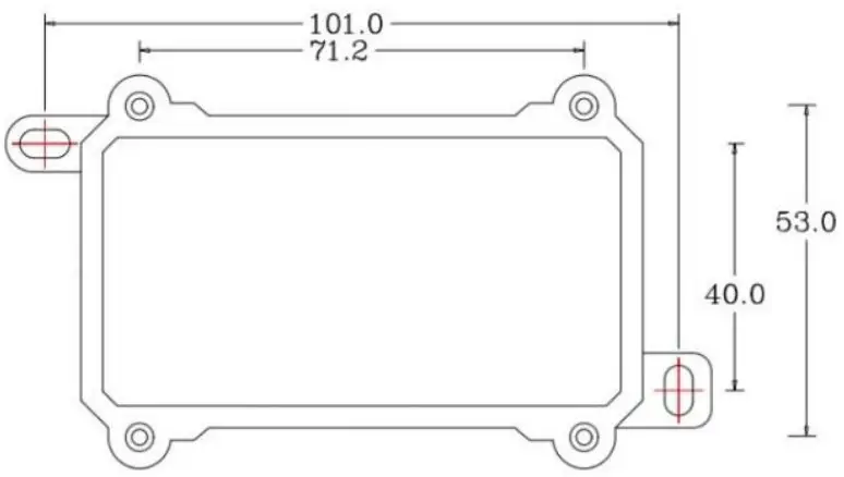
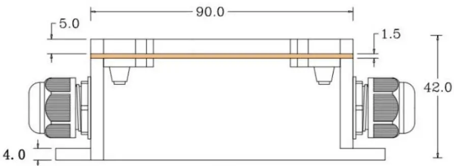
Dimension
Electrode Dimension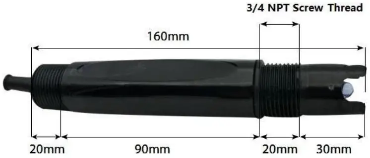
Transmitter Dimension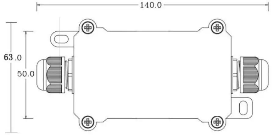
*Note: Do not put the Transmitter into the liquid.
Installation Maintenance and Calibration
Installation
Installation locations of Electrodes will vary depending on the system design. The key is to monitor good representative sample of the whole solution directly after introduction of chlorine. The installation location must allow for complete contact of the scrubber liquid with the probes. Some example installation locations for Electrodes include the following:
- Outlet of packed tower
- Outlet of recycle pump
- Pump bypass line
- Heat Exchanger bypass line
Maintenance
Under normal conditions, electrodes can last anywhere from several months to several years depending on the type of operation, rate of production, strength of product, and quality of the raw materials used in the process.
Because each application is different, there is no average life expectancy. Because the pH responsive glass bulb or flat surface is relatively thin, care should be taken so that the bulb does not become scratched or broken. It is also important that ORP measuring surfaces are not
scratched or gouged. The suggestions in this sheet are intended to help avoid these problems. Coating of an electrode’s measuring surface can lead to erroneous readings including shortened span and wrest pones times. The type of coating determines the type of cleaning technique. Soft Coatings cambered moved by vigorous stirring, by use of a squirt bottle or, very carefully, by gently wiping with aloft, cleaning-abrasive paper or cloth. Hard Coatings should be chemically removed. The chemical used tore move the coating should be the least harsh chemical that dissolves the coating in 1 or 2 minutes undoes not attack the electrode’s materials of construction. For example, a calcium carbonate coating might be removed with 5% HCl (muriatic acid). Oily or Organic Coatings are best removed with detergents or an appropriate solvent that does not attack the electrode’s materials of construction. For example, isopropyl alcohol might be used but acetone should be avoided if the electrode’s body is made of CPVC.
Output Signal Conversion
PH output conversion
| Output Interface | Parameters Range | Conversion Formula |
| Analog Voltage Output 0-2V | PH range: 0-14PH | PH=7.00*VOLTAGE.When VOLTAGE=1.0V,then PH=7.00*1.00=7. |
| RS485Modbus-RTU | PH range: 0-14PH | PH= (REGISTER VALUE)/100.When REGISTERVALUE=7000,then PH= 7000/100=7.00. |
| Temperature range: -40-80°C | TEMPERATURE= (REGISTERVALUE)/100.WhenREGISTER VALUE=2013,then TEMPERATURE= 2013/100=20.13°C. |
NOTE: The unit of VOLTAGE is (V)
RS485 Modbus Protocol
Modbus Protocol
Modbus Protocol is widely used to establish master-slave communication between intelligent devices or sensors. A MODBUS message sent from a master to a slave contains the address of the slave, the function code (e.g. ‘read register’ or ‘write register’), the data, and a check sum (LRC or CRC).
The sensor is RS485 interface with Modbus protocol. The default serial communication setting is slave address 1, Modbus rut, 9600bps, 8 data bits and 1 stop bit. All communication settings can be changed with Modbus command, and take effective after re-power up the sensor.
Following Modbus function code are supported by sensor.
Modbus Function Code 0x03 : used for reading holding register. Modbus Function Code 0x04 : used for reading input register. Modbus Function Code 0x06 : used for writing single holding register. Modbus Function Code 0x10: used for writing multiple holding registe
Modbus Register
| Parameters | Register Addr. (HEX/DEC) | Dat a Typ e | Modbu s Functio nCode(DEC) | Range and Comments | Defaul t Value |
| TEMPRATURE | 0x0000 /0 | INT16RO | 3/4 | -4000-8000 for -40.00~80.00°C. | N/A |
| PHPHVALUE | 0x0001 /1 | UINT16RO | 3/4 | 0-1400 for 0.00-14.00 | N/A |
| TEMPCOMPENSA TEE N | 0x0020 /32 | UINT16R/W | 3/6/16 | 0: ExternalTemperature sensor 1: Disabled | 1 |
| 2:On boardtemperature sensor | |||||
| PHCALIBRAWAD0 | 0x0030 /48 | UINT16 | 3/6/16 | -2000~2000 | N/A |
| PH calibration | R/W | for – | |||
| point for PH=4.01 | 2000~2000; | ||||
| Write 0xFFFF to | |||||
| calibrate. | |||||
| PHCALIBRAWAD1 | 0x0031 /49 | UINT16 | 3/6/16 | -2000~2000 | N/A |
| PH calibration | R/W | for – | |||
| point for PH=7.00 | 2000~2000; | ||||
| Write 0xFFFF to | |||||
| calibrate. | |||||
| PHCALIBRAWAD2 | 0x0032 /50 | UINT16 | 3/6/16 | -2000~2000 | N/A |
| PH calibration | R/W | for – | |||
| point for | 2000~2000; | ||||
| PH=10.01 | Write 0xFFFF to | ||||
| calibrate. | |||||
| SLAVEADDRESS | 0x0200 /512 | UINT16R/W | 3/6/16 | 0-255 | 1 or 12 |
| BAUDRATE | 0x0201 /513 | UINT16 | 3/6/16 | 0-6 | 3:9600bps |
| R/W | 0:1200bps | ||||
| 1:2400bps | |||||
| 2:4800bps | |||||
| 3:9600bps | |||||
| 4:19200bp | |||||
| s | |||||
| 5:38400bp | |||||
| s | |||||
| PROTOCOL | 0x0202 /514 | UINT16R/W | 3/6/16 | 0-10:Modbus RTU | 0:Modbu s RTU |
| PARITY | 0x0203 /515 | UINT16 | 3/6/16 | 0-2 | 0:Non |
| R/W | 0:Non | e | |||
| e | Parity | ||||
| 1:Eve | |||||
| n | |||||
| 2:Odd | |||||
| DATABITS | 0x0204 /516 | UINT16 | 3/6/16 | 1 | 1:8 databits |
| R/W | 1:8 databits | ||||
| STOPBITS | 0x0205 /517 | UINT16R/W | 3/6/16 | 0-10:1 stopbit1:2 stopbits | 0:1 stopbit |
| RESPONSEDELAY | 0x0206 /518 | UINT16R/W | 3/6/16 | 0-255 for 0-2550milliseconds | 0 |
| ACTIVEOUTPUTINTE RVAL | 0x0207 /519 | UINT16R/W | 3/6/16 | 0-255 for 0-255seconds. | 0 |
NOTE: UINT16:16 bit unsigned integer, INT16:16bit signed integer NOTE: RO: Register is Read Only, R/W: Register is Read/Write NOTE: HEX is Hexadecimal (data with 0x/0X prefix), DEC is Decimal
Modbus Register Detail Description
| TEMPERATURE | ||
| Data Range | -4000-8000 For -40.00~80.00°C | Default: N/A |
| Power Down Save | N/A | |
Note: Temperature value (Binary complement).
Example: When REGISTER = 0x0702 (HEX format), then
VALUE=(0x07*256+0x02)/100=17.94°C.When REGISTER=FF05H (HEX format),then
VALUE=((0xFF*256+0x05)-0xFFFF-0x01)/100 =(0xFF05-0xFFFF- 0x01)/100=-2.51°C.
| PH VALUE | ||
| Data Range | 0-1400 for 0-14.00PH | Default: N/A |
| Power Down Save | N/A | |
Note: PH value
Example: When REGISTER = 0x02BC (HEX format), then VALUE=(0x02*256+0xBC)/100=7.00PH
| TEMPCOMPENSATEEN | ||
| Data Range | 0: External Temperature sensor 1: Disabled2:On board temperature sensor | Default: 1 |
| Power Down Save | YES | |
Note: Temperature compensation
| PHCALIBRAWAD0 | ||
| Data Range | -2000~2000 | Default: N/A |
| Power Down Save | YES | |
Note: PH calibration AD value for PH=4.01; Immerse the electrode into PH=4.01solutionand wait until the reading value being stable, then write 0xFFFF to this register to calibrate.
| PHCALIBRAWAD1 | ||
| Data Range | -2000~2000 | Default: N/A |
| Power Down Save | YES | |
Note: PH calibration AD value for PH=7.00; Immerse the electrode into PH=7.00solutionand wait until the reading value being stable ,then write 0xFFFF to this register to calibrate.
| PHCALIBRAWAD | ||
| Data Range | 2000~2000 | Default: N/A |
| Power Down Save | YES | |
Note: PH calibration AD value for PH=10.01; Immerse the electrode into PH=10.01solutionand wait until the reading value being stable, then write 0xFFFF to this register to calibrate
| SLAVEADDRESS — Modbus Slave Address | ||
| Data Range | 0-255 | Default: 1 or 12 |
| Power Down Save | YES | |
Note: Please re-power on the sensor to take effective after set.
| BAUDRATE — Serial Comm Baudrate | ||
| Data Range | 0-50:1200bps 1:2400bps 2:4800bps 3:9600bps 4:19200bps5:38400bps | Default: 3 |
| Power Down Save | YES | |
Note: Please re-power on the sensor to take effective after set.
| PROTOCOL — Serial Comm Protocol | ||
| Data Range | 00:Modbus RTU | Default: 0 |
| Power Down Save | YES | |
Note: Please re-power on the sensor to take effective after set.
| PARITY — Serial Comm Parity | ||
| Data Range | 0-20:NONE1:EVEN2:ODD | Default: 0 |
| Power Down Save | YES | |
Note: Please re-power on the sensor to take effective after set.
| DATABITS — Serial Comm Databits | ||
| Data Range | 11:8 databits | Default: 1 |
| Power Down Save | YES | |
Note: Please re-power on the sensor to take effective after set.
| STOPBITS — Serial Comm Stopbits | ||
| Data Range | 0-10:1 stopbit1:2 stopbits | Default: 0 |
| Power Down Save | YES | |
Note: Please re-power on the sensor to take effective after set.
| RESPONSEDELAY — Serial Comm Response Delay | ||
| Data Range | 0-255 for 0-2550 milliseconds, 0 for disabled | Default: 0 |
| Power Down Save | YES | |
Note: Please re-power on the sensor to take effective after set.
Note: Sensor will delay a period before response to master request command.
Example: When set to 5 and receive a request from master device, then sensor will delay 5*10ms=50ms, then response to master.
| ACTIVEOUTPUTINTERVAL — Serial Comm Active Output Interval time | ||
| Data Range | 0-255 for 0-255 seconds, 0 for disabled | Default: 0 |
| Power Down Save | YES | |
Note: Please re-power on the sensor to take effective after set.
Note: Sensor will output the data actively without any master request command.
Note: Only ONE sensor should be on RS485 network, or there will be data collisionandcorrupt the data on line.
Note: Use key button to restore the serial comm parameters factory value to exit theactive output mode.
Example: When set to 5 then sensor will output the data every 5 seconds without any master request command.
Modbus Function Code
For description below, data started with 0X/0x means that it’s in HEX format
Function Code 3 Protocol Example
Master Request: AA 03 RRRR NNNN CCCC
| AA | 1 byte | Slave Address,0-255 |
| 0x03 | 1 byte | Function Code 3 |
| RRRR | 2 byte | Starting Register Addr |
| NNNN | 2 byte | Quantity of Register to read |
| CCCC | 2 byte | CRC CHECKSUM |
Slave Response: AA 03 MM VV0 VV1 VV2 VV3… CCCC
| AA | 1 byte | Slave Address,0-255 |
| 0x03 | 1 byte | Function Code 3 |
| MM | 1 byte | Register Data Byte Count |
| VV0,VV1 | 2 byte | Register Value (High8bits first) |
| VV2,VV3 | 2 byte | Register Value (High8bits first) |
| … | … | Register Value (High8bits first) |
| CCCC | 2 byte | CRC CHECKSUM |
Example: Read register 0x0200-0x0201,that is slave address and baudrate. Master Request:01 03 0200 0002 C5B3
| Slave Addr. | 1 byte | 0x01 |
| Function Code | 1 byte | 0x03 |
| Starting RegisterAddr. | 2 byte | 0x0200 |
| Quantity of Registerto read | 2 byte | 0x0002 |
| Checksum | 2 byte | 0xC5B3 |
Slave Response: 01 03 04 00 01 00 03 EB F2
| Slave Addr. | 1 byte | 0x01 |
| Function Code | 1 byte | 0x03 |
| Register Data ByteCount | 1 byte | 0x04 |
| Register Value:Address | 2 byte | 0x00(HIGH 8 Bits) |
| 0x01(LOW8 Bits) | ||
| Register Value:Baudrate | 2 byte | 0x00(HIGH 8 Bits) |
| 0x03(LOW8 Bits) | ||
| Checksum | 2 byte | 0xEBF2 |
Function Code 4 Protocol Example
Master Request: AA 04 RRRR NNNN CCCC
| AA | 1 byte | Slave Address,0-255 |
| 0x04 | 1 byte | Function Code 4 |
| RRRR | 2 byte | Starting Register Addr |
| NNNN | 2 byte | Quantity of Register to read |
| CCCC | 2 byte | CRC CHECKSUM |
Slave Response: AA 04 MM VV0 VV1 VV2 VV3… CCCC
| AA | 1 byte | Slave Address,0-255 |
| 0x04 | 1 byte | Function Code 4 |
| MM | 1 byte | Register Data Byte Count |
| VV0,VV1 | 2 byte | Register Value (High8bits first) |
| VV2,VV3 | 2 byte | Register Value (High8bits first) |
| … | … | Register Value (High8bits first) |
| CCCC | 2 byte | CRC CHECKSUM |
Example: Read register 0x0000-0x0002,that is temperature, PH value. Master Request: 01 04 0000 0002 71CB
| Slave Addr. | 1 byte | 0x01 |
| Function Code | 1 byte | 0x04 |
| Starting RegisterAddr. | 2 byte | 0x0000 |
| Quantity of Registerto read | 2 byte | 0x0002 |
| Checksum | 2 byte | 0x71CB |
Slave Response: 01 04 04 08C3 029E 8910
| Slave Addr. | 1 byte | 0x01 |
| Function Code | 1 byte | 0x04 |
| Register Data Byte Count | 1 byte | 0x04 |
| Register Value: Temperature | 2 byte | 0x08(HIGH 8 Bits) |
| 0xC3(LOW8 Bits) | ||
| Register Value: PH | 2 byte | 0x02(HIGH 8 Bits) |
| 0x9E(LOW8 Bits) | ||
| Checksum | 2 byte | 0x8910 |
Temperature =(0x08*256+0xC3)/100=2243/100=22.43 °C PH=(0x02*256+0x9E)/100=670/100=6.70PH
Function Code 6 Protocol Example
Master Request: AA 06 RRRR VVVV CCCC
| AA | 1 byte | Slave Address,0-255 |
| 0x06 | 1 byte | Function Code 6 |
| RRRR | 2 byte | Register Addr (High8bits first) |
| VVVV | 2 byte | Register Value (High8bits first) |
| CCCC | 2 byte | CRC CHECKSUM |
Slave Response: AA 06 RRRR VVVV CCCC
| AA | 1 byte | Slave Address,0-255 |
| 0x06 | 1 byte | Function Code 6 |
| RRRR | 2 byte | Register Addr (High8bits first) |
| VVVV | 2 byte | Register Value (High8bits first) |
| CCCC | 2 byte | CRC CHECKSUM |
Example: Write Register 0x0020,that is set temperature compensation
Request: 01 06 0020 0000 8800
| Slave Addr. | 1 byte | 0x01 |
| Function Code | 1 byte | 0x06 |
| Register Addr. | 2 byte | 0x0020 (High8bits first) |
| Register Value | 2 byte | 0x0000 (High8bits first) |
| Checksum | 2 byte | 0x8800 |
Response: 01 06 0021 0001 1800
| Slave Addr. | 1 byte | 0x01 |
| Function Code | 1 byte | 0x06 |
| Register Addr. | 2 byte | 0x0020 (High8bits first) |
| Register Value | 2 byte | 0x0000 (High8bits first) |
| Checksum | 2 byte | 0x8800 |
Function Code 16 Protocol Example
Master Request: AA 10 RRRR NNNN MM VVVV1 VVVV2 …CCCC
| AA | 1 byte | Slave Address,0-255 |
| 0x10 | 1 byte | Function Code 0x10 |
| RRRR | 2 byte | Starting Register Addr |
| NNNN | 2 byte | Quantity of Register to write |
| MM | 1 byte | Register Data Byte Count |
| VVVV1 | 2 byte | Register Value(High8bits first) |
| VVVV2 | 2 byte | Register Value(High8bits first) |
| … | … | Register Value(High8bits first) |
| CCCC | 2 byte | CRC CHECKSUM |
Slave Response: AA 10 RRRR NNNN CCCC
| AA | 1 byte | Slave Address,0-255 |
| 0x10 | 1 byte | Function Code 0x10 |
| RRRR | 2 byte | Starting Register Addr |
| NNNN | 2 byte | Quantity of Register to write |
| CCCC | 2 byte | CRC CHECKSUM |
Example: Write Register 0x0200-0x0201,that is set slave address to 1,andbaudrateto 19200bp. Master Request:01 10 0200 0002 04 0001 0004 BACC
| 0x01 | 1 byte | Slave Addr. |
| 0x10(HEX) | 1 byte | Function Code 0x10 |
| 0x0200 | 2 byte | Starting Register Addr |
| 0x0002 | 2 byte | Quantity of Register to write |
| 0x04 | 1 byte | Register Data Byte Count |
| 0x0001 | 2 byte | Register Value: Slave Address 1 |
| 0x0004 | 2 byte | Register Value: Baudrate 19200bps |
| 0xBACC | 2 byte | CRC CHECKSUM |
Salve Response: 01 10 0200 0002 4070
| 0x01 | 1 byte | Slave Addr. |
| 0x10(HEX) | 1 byte | Function Code 0x10 |
| 0x0200 | 2 byte | Starting Register Addr(High8bits first) |
| 0x0002 | 2 byte | Quantity of Register to write(High8bits first) |
| 0x4070 | 2 byte | CRC CHECKSUM |
Software Configuration Utility
You can use software listed below to try reading/writing the register of sensor:
https://github.com/ed-chemnitz/qmodbus/releases
http://qmodbus.sourceforge.net/
Document Version
| Version | Date | Description | Editor |
| V2.0 | First edition | ||
| V2.1 | 11/18/2022 | Add Note in chapter 3 | Kelvin.Lee |
Mouser Electronics
Authorized Distributor
Click to View Pricing, Inventory, Delivery & Lifecycle Information:
Seeed Studio: 10199066