ABB 2CMC485019M0201 kWh Meters
![]() Warning! Installation by person with electrotechnical expertise only
Warning! Installation by person with electrotechnical expertise only
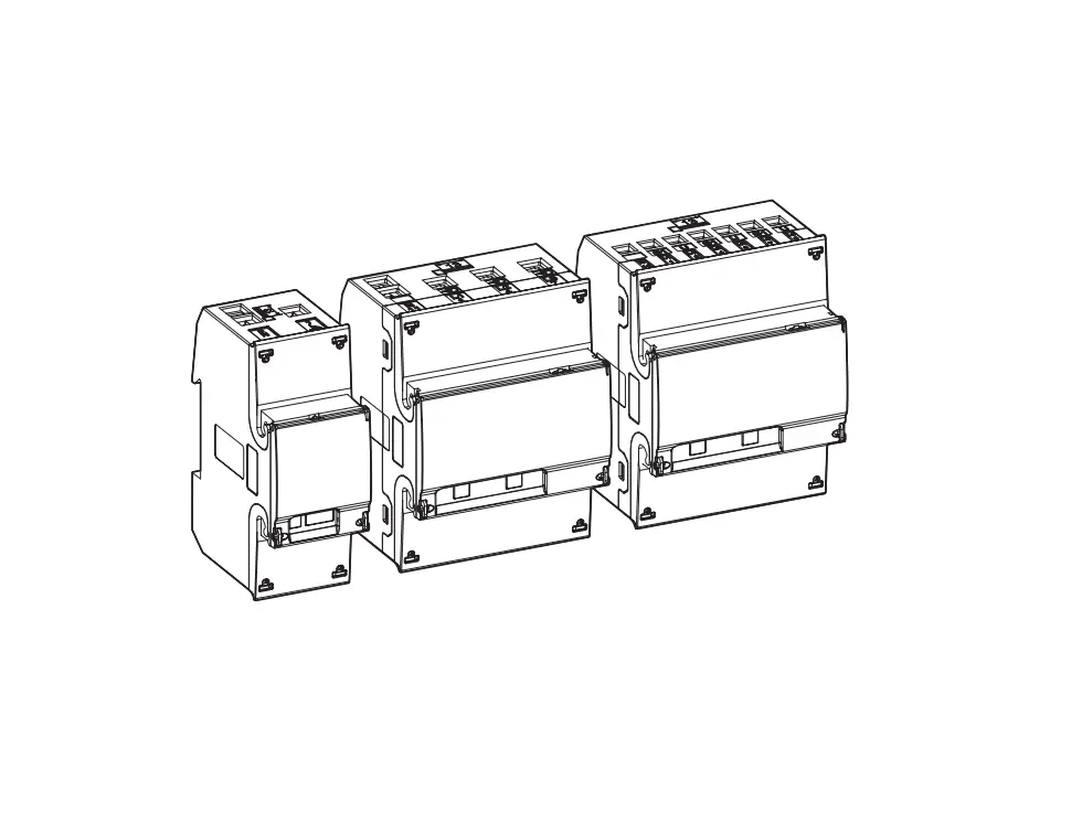
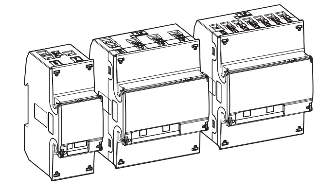
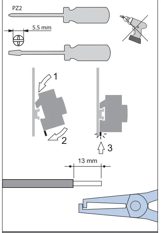
Mounting
Mounting all model
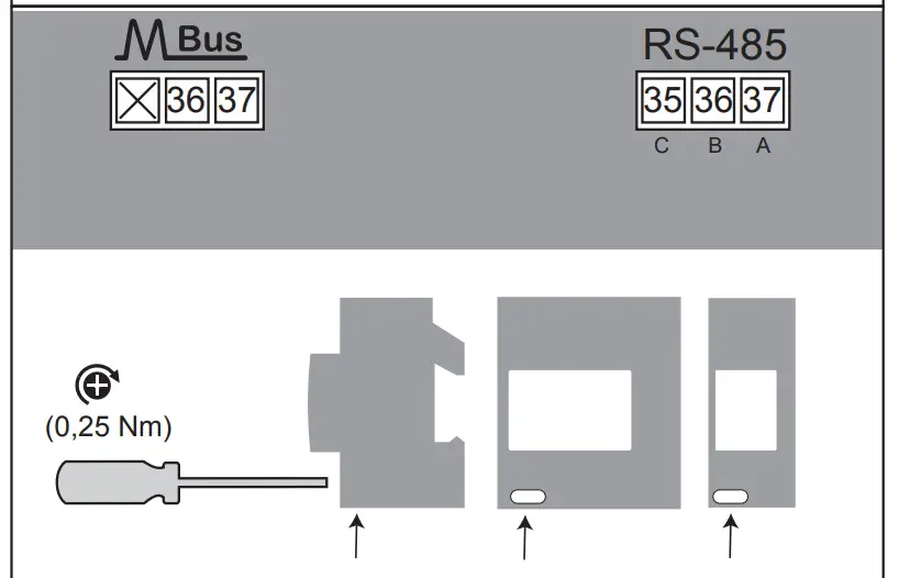
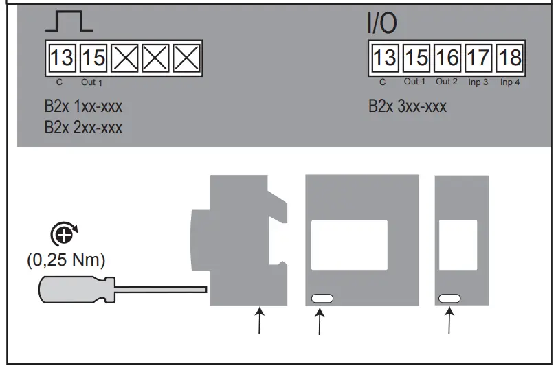
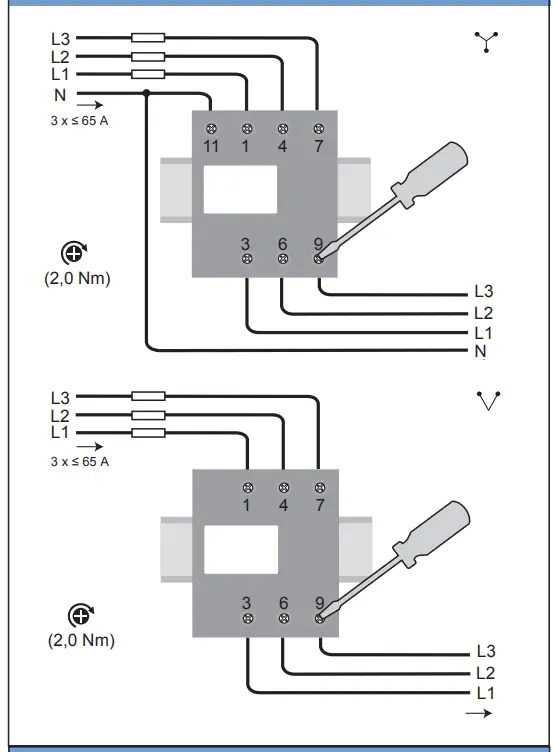
Connection -B24
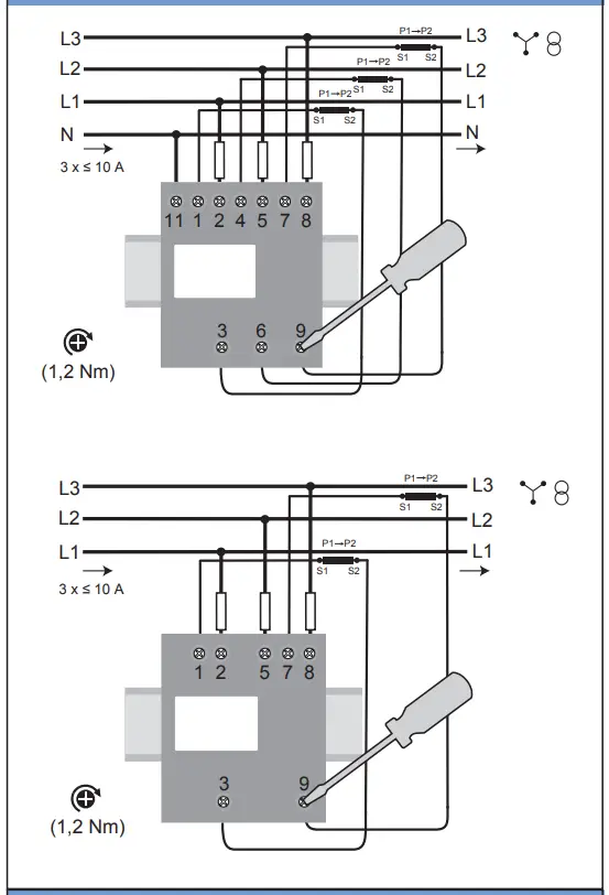
Connection -B23
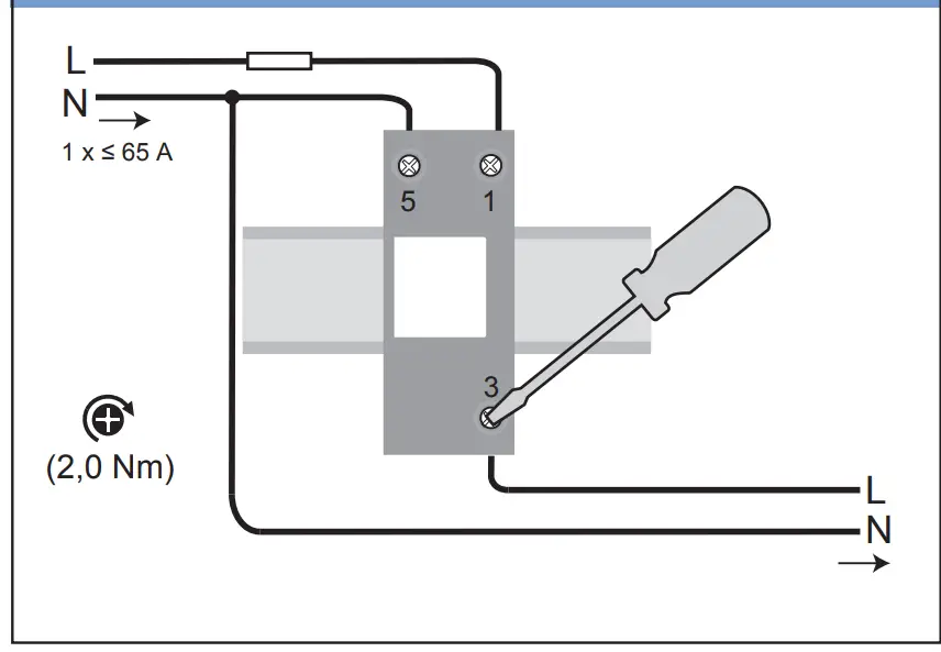
Connection -B21
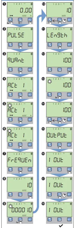
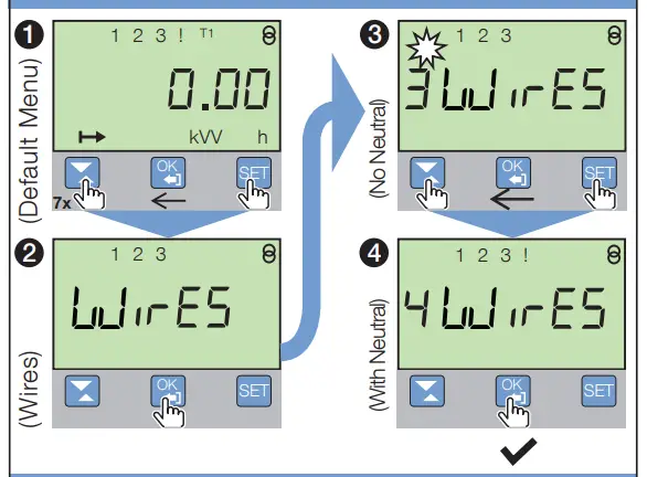
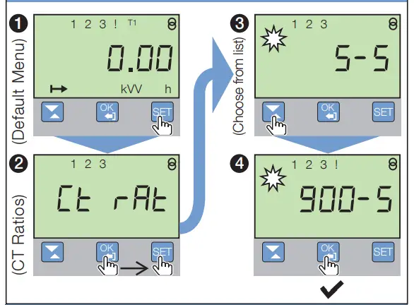
Explanations
| Button | Function |
 | Down / Up |
 | OK / Exit |
 | Set |
| Symbol | Action |
 | Press this button |
 | Press and hold button |
 | Setting sequence |
 | Screen is flashing |
| Number of keystrokes |
| Setting finished |
Basic settings
Default settings
| Pulse output Pulse 1 Quantity : Active Energy Import Frequency: 100 Imp/kWh Length: 100 ms Output: 1 | Pulse output Pulse 1 Quantity : Active Energy Import Frequency: 10 Imp/kWh Length: 100 ms Output: 1 |
| Pulse 2 Quantity : Active Energy Export Frequency: 100 Imp/kWh Length: 100 ms Output: 2 | Pulse 2 Quantity : Active Energy Export Frequency: 10 Imp/kWh Length: 100 ms Output: 2 |
| B23/B24 | B24 |
| Wires Wires: 4 Wires (3 Phases & Neutral) | CT Ratios CT Ratios: 5/5 |
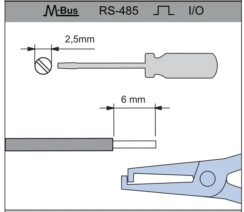
B21/B23/B24 – Pulse output
B23/B24 – Wires
B24 – CT Ratios
Change / Select values
- Select a value Select a value when the digit blinks

Example: Set CT Ratio 100/5
- Cancel a value

- Change Value Enter the value when the digit blinks.

Example: Set 10 to 20

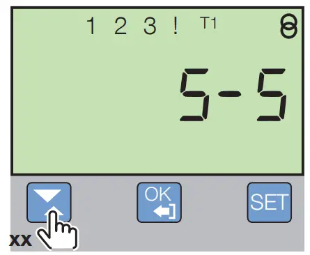
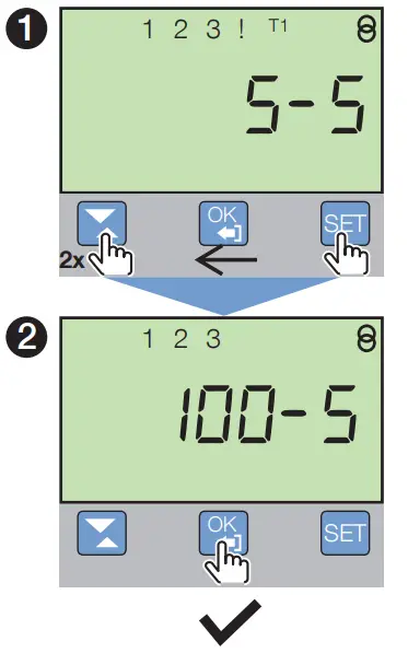
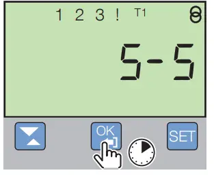
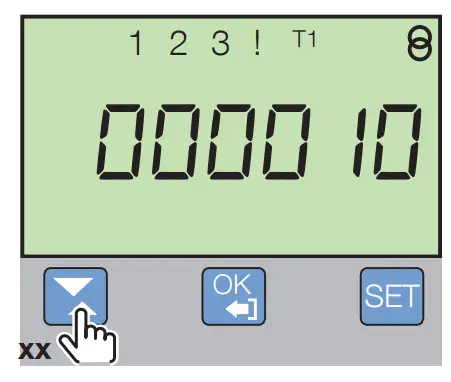
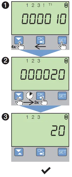
Table 3 Technical data
| B21 | B23 | B24 | |
| Nominal voltage | 230 V AC | B24 Nominal voltage 230 V AC 3×230/400 V AC | |
| Voltage range | 220-240 VAC (-20% to +15%) | ) 3×220-240 V AC (-20% to +15%) | |
| Base current Ib | 5 A | ||
| Rated current In | – | ||
| Reference current Iref | 5 A | ||
| Maximum current Imax | 65 A | ||
| Terminal wire area | 1.5 – 25 mm2 | ||
| Frequency | 50 or 60 Hz ± 5% | ||
| Accuracy Class | B (Cl. 1) and Reactive Cl. 2 | 2 B (Cl. 1) and Reactive Cl. 2 | B (Cl. 1) or C (Cl. 0,5 S) and Reactive Cl. 2 |
| Active energy | 1% | 0.5%, 1% | |
| Environmental | |||
| Operating temperature | -40 to +70°C | ||
| Storage temperature | -40°C to +85°C | ||
| Humidity | 75% yearly average, 95% on 30 days/year | ||
| Resistance to water and dust | IP20 on terminal block without protective enclosure and IP51 in protective enclosure, according to IEC 60529. | ||
| Mechanical env. | Class M2 for MID meters | ||
| Electromagnetic env. | Class E2 for MID meters | ||
| Frequency | Length | ||
| LED pulse inducator | 1000 imp/kWh | 40 ms | |
| Outputs | |||
| Current | 2 – 100 mA | ||
| Voltage | 5 – 240 V AC/DC. 5 – 40 V DC. For meters with only 1 output | ||
| Pulse output frequency | Programmable: 1 – 999999 imp/kWh | ||
| Pulse length | Programmable: 10 – 990 ms | ||
| Terminal wire area | 0.5 – 1 mm2 | ||
| Inputs | |||
| Voltage | 0 – 240 V AC/DC | ||
| OFF | 0 – 12 V AC/DC | ||
| ON | 57 – 240 V AC/24 – 240 V DC | ||
| Min. pulse length | 30 ms | ||
| Terminal wire area | 0.5 – 1 mm2 | ||
| Standards | IEC 62052-11, IEC 62053-21 class 1 & 2, IEC 62053-22 class 0,5 S, IEC 62053-23 class 2, IEC 62054-21, GB/T 17215.211- 2006, GB/T 17215.312-2008 class 1 & 2, GB/T 17215.322-2008 class 0,5 S, GB 4208-2008, EN 50470-1, EN 50470-3 category A, B & C | ||
| Material | Polycarbonate in transparent front glass. Glass reinforced polycarbonate in bottom case and upper case. Polycarbonate in terminal cover | ||
Disclaimer
The information in this document is subject to change without notice and should not be construed as a commitment by ABB AB. ABB AB assumes no responsibility for any errors that may appear in this document.
In no event shall ABB AB be liable for direct, indirect, special, incidental or consequential damages of any nature or kind arising from the use of this document, nor shall ABB AB be liable for incidental or consequential damages arising from use of any software or hardware described in this document.
![]() Warning – Working with high voltage is potentially lethal. Persons subjected to high voltage may suffer cardiac arrest, burn injuries, or other severe injuries. To avoid such injuries, make sure to disconnect the power supply before you start the installation. Electrical equipment should only be installed, accessed, serviced and maintained by qualified electrical personnel.
Warning – Working with high voltage is potentially lethal. Persons subjected to high voltage may suffer cardiac arrest, burn injuries, or other severe injuries. To avoid such injuries, make sure to disconnect the power supply before you start the installation. Electrical equipment should only be installed, accessed, serviced and maintained by qualified electrical personnel.
![]() Warning – For safety reasons it is recommended that the equipment is installed in a way that makes it impossible to reach or touch the terminal blocks by accident.
Warning – For safety reasons it is recommended that the equipment is installed in a way that makes it impossible to reach or touch the terminal blocks by accident.
The best way to make a safe installation is to install the unit in an enclosure. Further, access to the equipment should be limited through use of lock and key, controlled by qualified electrical personnel.
![]() Warning – The meters must always be protected by fuses on the incoming side. In order to allow for maintenance of transformer rated meters, it is recommended that there should be a short circuiting device installed near the meter. Do not operate the equipment outside the specified technical data.
Warning – The meters must always be protected by fuses on the incoming side. In order to allow for maintenance of transformer rated meters, it is recommended that there should be a short circuiting device installed near the meter. Do not operate the equipment outside the specified technical data.
Installation Requirements
To comply with the protection requirements the meter must be mounted in protection class IP 51 enclosures, or better, according to IEC 60259.
Troubleshooting
If any of the following icons ![]() appear in the display after the installation has been completed and power has been connected to the meter, refer to the B21/B23/B24 User Manual for detailed information
appear in the display after the installation has been completed and power has been connected to the meter, refer to the B21/B23/B24 User Manual for detailed information
Service and Maintenance
The meter contains no parts that can be repaired or exchanged. A broken meter must be replaced. If the meter needs to be cleaned, use a lightly moistened cloth and a mild detergent to wipe i
Caution – Be careful that no liquid gets into the meter since it may damage the equipment.
Declaration of conformity
Download the Declaration of conformity by scanning the QR codes below with a QR code reader on your mobile device
B21 and B23

B24

Note
Warranty and accuracy are void if sealing labels are removed.