![]() OPERATOR ADAPTER ABF
OPERATOR ADAPTER ABF
Installation Instructions for Allen-Bradley Bulletin 1494F Series B Disconnect Switches
(For parts list, see Page 2)
ABF Operator Adapter Universal Cutout
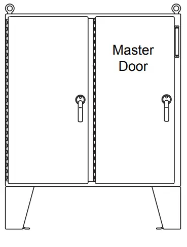
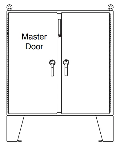
For floor-mounted enclosures with the disconnect on the nght flange
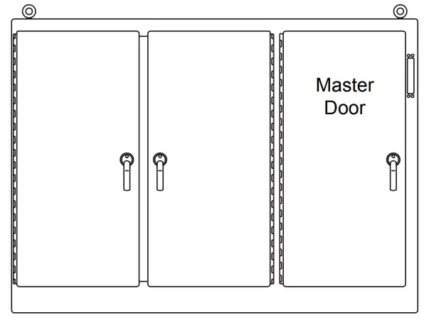
For one- through six-door free-standing enclosures with the disconnect the the right flange
For floor-mounted enclosures with the disconnect on the centerpost
![]() WARNING
WARNING
The functions, fits and clearances of the installation described hereon are calculated from information supplied by the manufacturers of the equipment to be installed. Be certain to check the function, fits and clearances of all equipment both before and after installation to assure that it operates properly and safely and meets all applicable codes, standards and regulations.
In the event the completed installation does not function properly or fails to meet any such codes, standards or regulations, do not attempt to make alterations or operate the equipment. Report such facts immediately to:
Hoffman Customer Service
2100 Hoffman Way
Anoka, MN 55303
763.422.2211
http://hoffman.nvent.com/contact-us
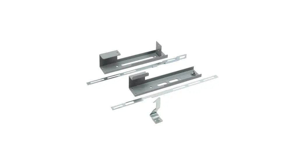
Parts List
Operator Adapter, Catalog Number ABF, for Allen-Bradley Bulletins 1494F Disconnects
| Item No. | Description | Part No. | Qty. |
| 1 | ADAPTER PLATE | 89056331 | 1 |
| 2 | PLATE GASKET | 89109613 | 1 |
| 3 | SCREW, 1/4-20X1/2 PAN HEAD | 99401031 | 4 |
| 4 | DOOR CATCH | 23101002 | 1 |
| 5 | SCREW, 10-32X3/8 PAN HEAD | 99401007 | 2 |
| 6 | LOCKWASHER, #10 EXTERNAL | 99401329 | 2 |
| 7 | SLIDE ARM | 26250001 | 1 |
| 8 | SHOULDER COLLAR, 5/8 DIAMETER | 26149001 | 1 |
| 9 | SCREW, 1/4-20X5/8 DIAMETER | 99401030 | 1 |
| 10 | WASHER, FLAT | 22101003 | 2 |
| 11 | LOCKWASHER, 1/4 SPRING | 99401318 | 11 |
| 12 | NUT, 1/4-20 HEX | 99401406 | 14 |
| 13 | THREADED ROD 1/4-20X17.88 | 22155002 | 4 |
| 14 | NYLON WASHER | 26132003 | 4 |
| 15 | INSTALLATION INSTRUCTIONS | 89114652 | 1 |
INTRODUCTION
This installation instruction is for the Allen−Bradley 1494F Series B.
These mechanisms are for disconnect switches mounted in Hoffman two door, floor mounted enlcosures with cutout on right hand flange or centerpost and one through six door, free−standing enclosures with the disconnect on the right flange.
1494F Series B Installation Steps
- Drill and tap holes required in panel; see Allen-Bradley Fixed Depth Disconnect Switch Installation Instructions. Two holes are required for un-fused switches; three holes for fused switches. Two holes are required for circuit breakers.
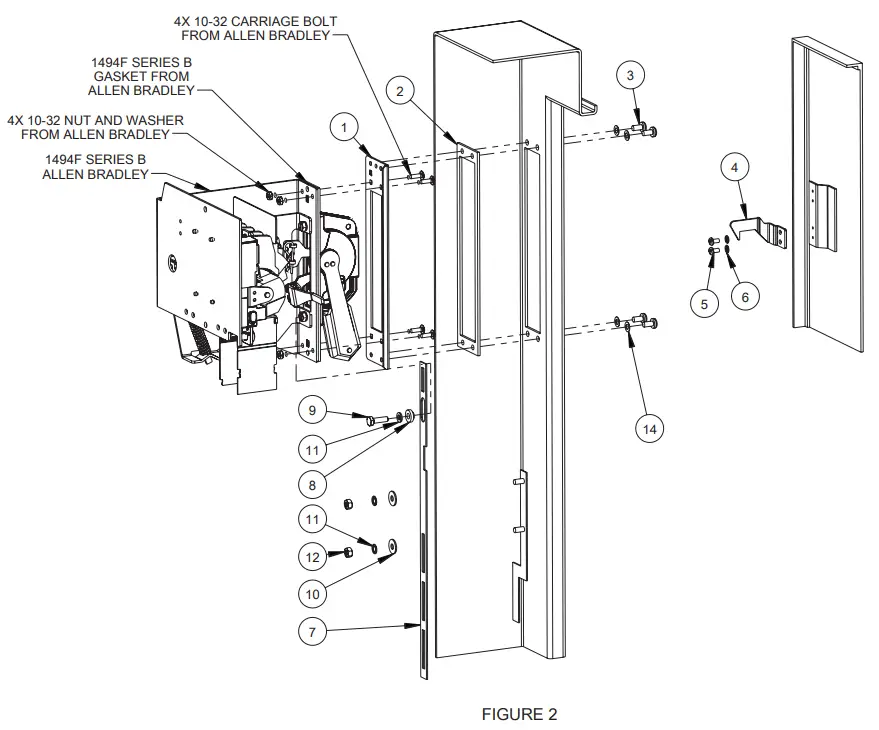
Reference Figure 1 and Figure 2 for the following steps: - Install adapter plate (item 1) and plate gasket (item 2) on the inside of the enclosure, behind the rectangular opening provided.
Gasket side with PSA should be attached to the adapter plate. Secure in place with four screws (item 3) and four nylon washers (Item 14).. - Install 1494F Series B
Use Allen Bradley instructions that come with the 1494F disconnect using the four carriage bolts provided by Allen−Bradley. - Install Slide Arm.
Note: When mounting to centerpost, cut 2.50 inches off bottom of slide arm (item 7). Bottom of slide arm has three rectangular slots.
Remove bottom screw from Allen−Bradley operating handle.
Install the slide arm (item 7) over the defeater part of the Allen−Bradley operating handle as shown.
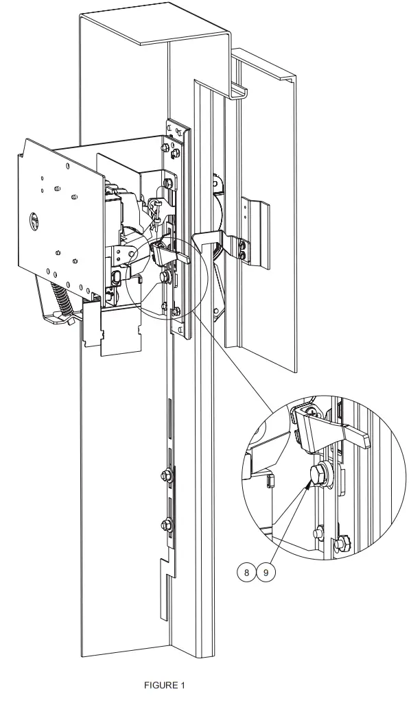
Note that the notch in the slide arm is positioned toward the door opening. Place the smaller diameter end of the shoulder collar (item 8) through the oval slot in the slide arm. Install long cap screw (item 9) with lock washer (item 11) through shoulder collar into the bottom mounting hole of the Allen−Bradley operating handle and tighten. The slide arm should move up and down smoothly. Install Allen−Bradley defeater bracket per Allen−Bradley instructions. - Attach the bottom of the slide arm (item 7) to the offset arm of the operator release mechanism. Use two flat washers (item 10), two lock washers (item 11), and two hex nuts (item 12). Do not tighten until parts are adjusted. (See Step 6b).
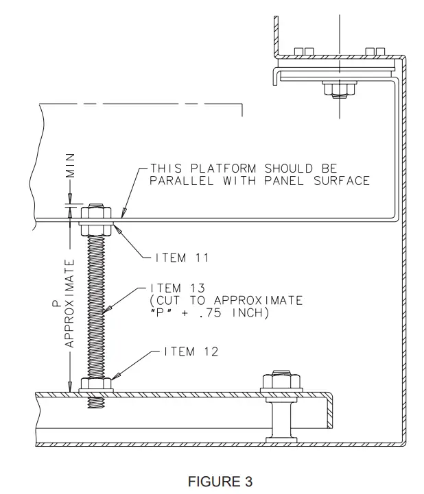
- The operator release mechanism is adjustable in two places.
Check the adjustment of the factory-installed roller bracket. The door latch should hit against the latch portion of the roller bracket when the door is closed and latched. Adjust up or down if necessary. The mechanism will then provide the necessary up−down motion required to operate the safety lock release in the Allen−Bradley operating handle.
Adjust the length of the slide arm assembly with proper adjustment of the slide arm. The safety lock (in the Allen−Bradley operating handle) should release just before the master door is fully latched. Lengthen slide arm if safety lock releases too soon.
Shorten slide arm if safety lock releases too late. - Attach the door catch (item 4) provided by Hoffman to the tapped spacer on the door using the bottom set of mounting holes.
Use two screws (item 5) and two lock washers (item 6). The door catch prevents the door from being opened when the AllenBradley operating handle is in the “ON” position.
| Enclosure | 1494 Series B | ||
| A21 | Depth | 30/60 AMP | 100/200 AMP |
| 12. | 3.50 | 2. | |
| 18. | 9.50 | 8. | |
| 24. | 15.50 | 14. | |
| A28/A43LD 1 and 2 Door | 12. | 3.50 | 2. |
| 18. | 9.50 | 8. | |
| 24. | 15.50 | 14. | |
| A28/A43LD 3 – 6 Door | 18. | 8.50 | 7. |
| 24. | 14.50 | 13. | |
| A34 | 18. | 8.50 | 7. |
| 24. | 14.50 | 13. | |
| A21 Centerpost | 12. | 3.50 | 2. |
| 18. | 9.50 | 8. | |
© 2018 Hoffman Enclosures Inc.
PH 763 422 2211 • nVent.com/HOFFMAN
89115482


