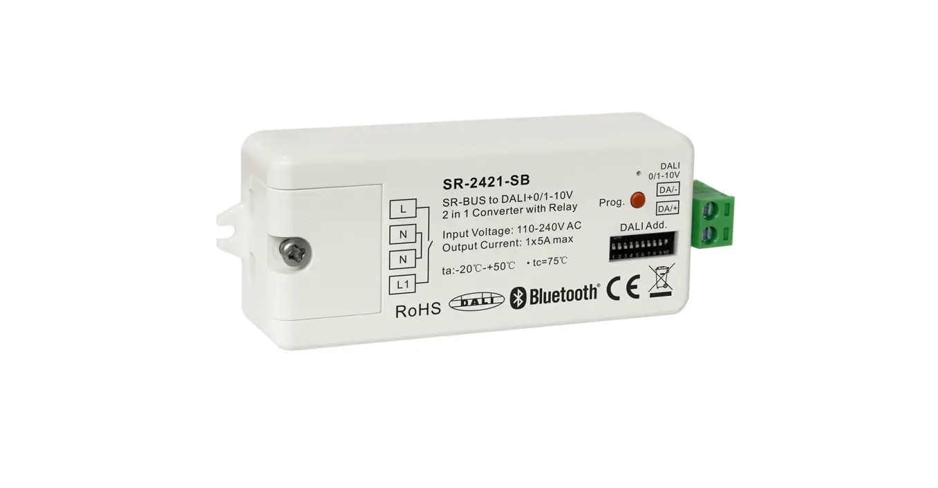
sunricher SR-2421 Bluetooth DALI interface 0-10V 1-10V
Important: Read All Instructions Prior to Installation
Function introduction
Product Data
| Input | Output, DALI | Output, 0/1-10V | Output, relay | Environment | Others | ||||
| Power | Signal | DALI PS current | DALI current consumption | Current | Switching voltage | Current | Operating temperature | Relative humidity | Dimensions |
| 110-240VAC | Bluetooth+RF 2.4GHz | Max. 50mA | Max. 4mA | Max. 20mA | 110-240VAC | Max. 5A | -20℃-+50℃ | 8% to 80% | 80x36x20.5mm |
- Bluetooth+RF to DALI+0/1-10V 2 in 1 converter, bluetooth mesh network
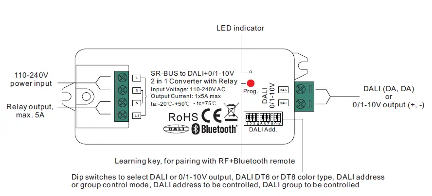
- Bluetooth+RF signal input, DALI signal output to DALI line or 0/1-10V signal output, 110-240VAC power input
- With max. 5A relay output and metering function
- Controlled through both RF remote and smart App, no gateway required
- Easy & quick pairing to the smart App by simply pushing the Prog. button
- Mesh network, much longer control distance, transmits received signal to neighbor devices
- Cloud control is available for remote access, works with Amazon Alexa and Google Home
- DALI signal or 1-10V signal output selectable by DIP switch
- Built-in DALI bus power supply, no extra DALI bus PS required
- With max. 50mA DALI bus power current output
- To supply control current to up to 25 DALI control gears
- DALI DT6 or DT8 device type selectable by DIP switch under DALI mode
- Color control according to DALI specifications of Device Type 8,
- Color type: Tc, XY coordinates, RGBW selectable by DIP switches
- DALI address control mode or group control mode selectable by DIP switch
- Enables to select the DALI address (00-63) to be controlled by DIP switches
- Enables to select the DALI group (0-15) to be controlled by DIP switches
- Enable to control 1 DALI Group of devices or 1 DALI Address on DALI line
- Enable to control all devices on DALI line via broadcast
- Waterproof grade: Ip20
Safety & Warnings
- DO NOT set the DIP switches with power applied to the device.
- DO NOT install with power applied to device.
- DO NOT expose the device to moisture.
Operation
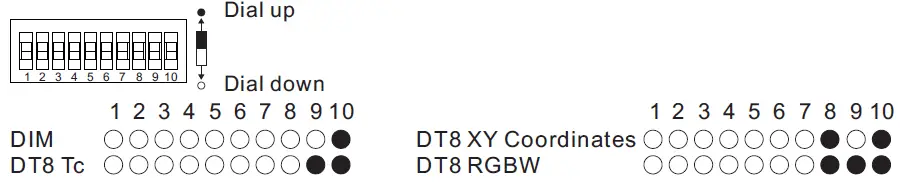
- Select DALI or 0/1-10V Output Using Dial Switch 10

Note: please first select output signal by the dial switch. - Select DALI Device Type (DT6/DT8 Color Type) to be Controlled Using Dial Switches 8-9

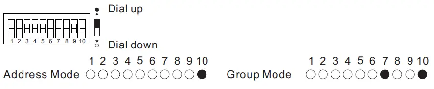
Note: once DALI output is selected, please then select the DALI device type you would like to control by the dial switches. - Select DALI Address or Group Control Mode Using Dial Switch 7

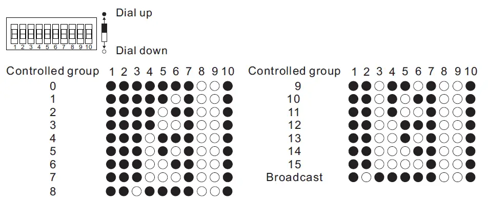
Note: once DALI device type is selected, please then select address control mode or group control mode by dial switch. - Select the DALI Group to be Controlled Using Dial Switches 2-6
Note: here device type is selected as DIM as an example, please select your correct DALI device type.
Note:- once DALI device type and group control mode are selected, please then select the DALI group (0-15 selectable) to be controlled on DALI line by dial switches.
- The control gears that are assigned to the selected DALI group on DALI line will be controlled.
- The control gears shall be first grouped by a DALI master controller, please refer to the user manual of corresponding master controller.
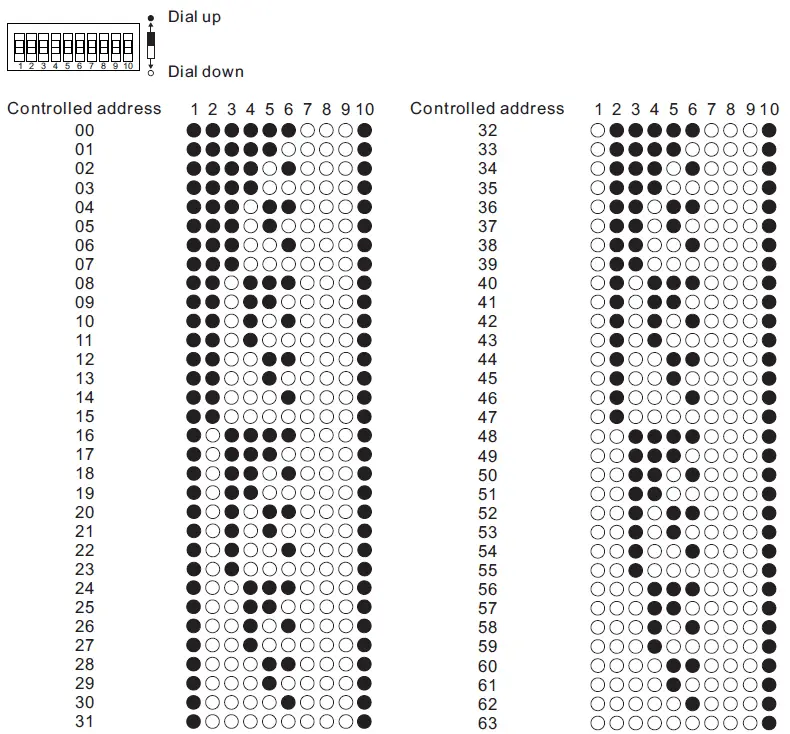
- Select the DALI Address to be Controlled Using Dial Switches 1-6
Note: here device type is selected as DIM as an example, please select your correct DALI device type.
- once DALI device type and address control mode are selected, please then select the DALI address (00-63 selectable) to be controlled on DALI line by dial switches.
- The control gear with the selected DALI address on DALI line will be controlled.
- Do wiring after above all settings are completed according to wiring diagram.
- Pair/delete the pairing with RF+Bluetooth remote
- Do wiring according to connection diagram.
- Pair LED controller with RF+Bluetooth remote: please refer to the instruction of the remote that you would like to pair with.
- Delete the pairing:
- Wire up the LED controller correctly, power on.
- Press and hold down the “Prog.” button on the controller for over 3 seconds (or reset power of the device 8 times continuously if the button is not accessible to factory reset the device) until the connected light flashes, which means well deleted.
Note: factory resetting will restore all configured parameters of the device on the APP to factory default setting.
- Pair with smart APP
- Do wiring according to connection diagram.
- Please refer to the EasyThings App user manual for details of adding device.

Wiring Diagram
When 0/1-10V Output Selected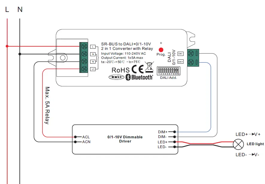 When DALI Output Selected
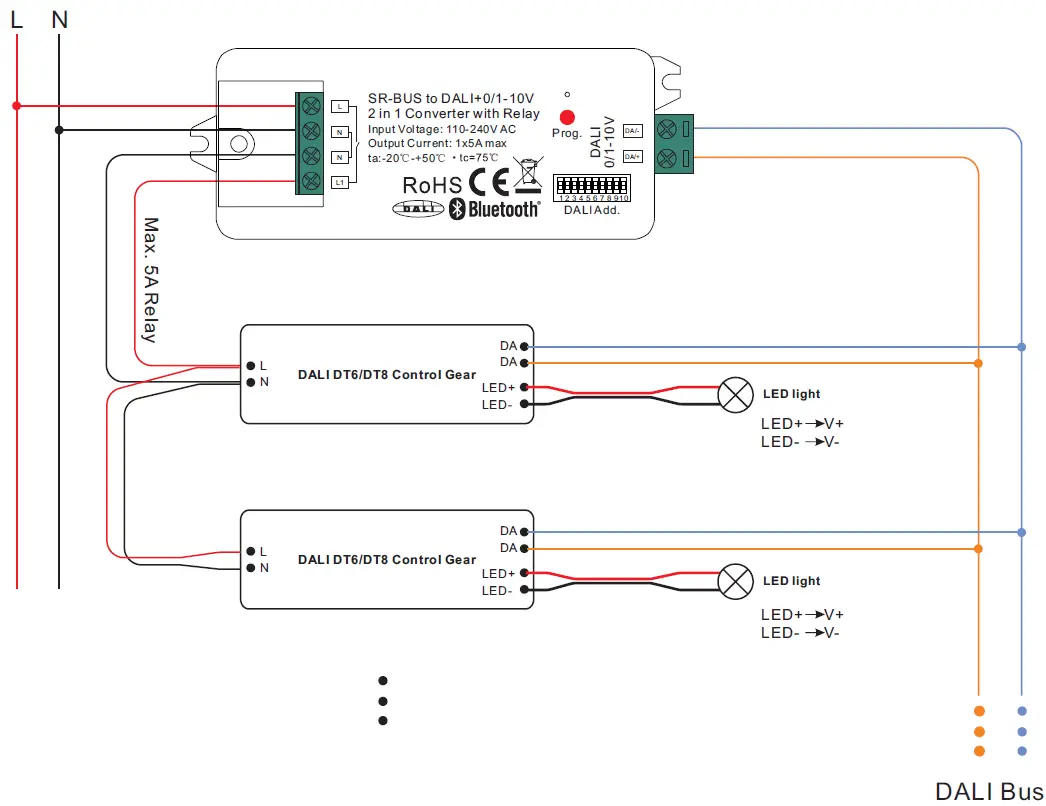 Note:
Note:
- Max. 50mA DALI bus PS output to supply control current to up to 25 control gears.
- The max. load of the relay is 5A, and the number of control gear can be switched by the relay depends on the load of each control gear.


