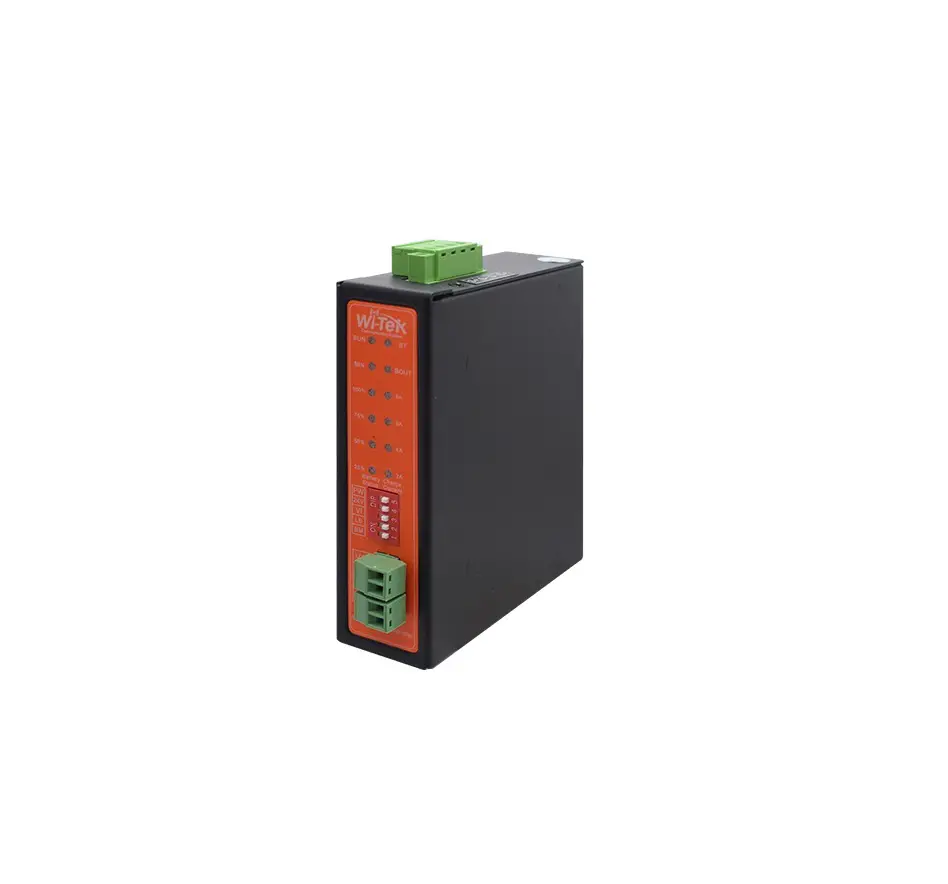
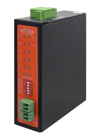
Wi-Tek WI-PS301G-UPS Solar Controller
Package Contents
|
|
|
 1 × Solar Controller
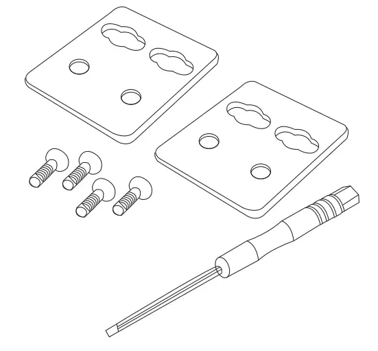 1× Mounting Accessory Kit
 1× Quick Installation Guide
Hardware Introduction
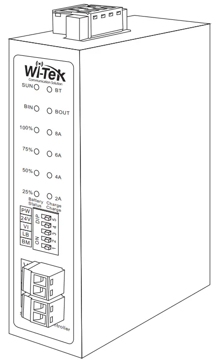
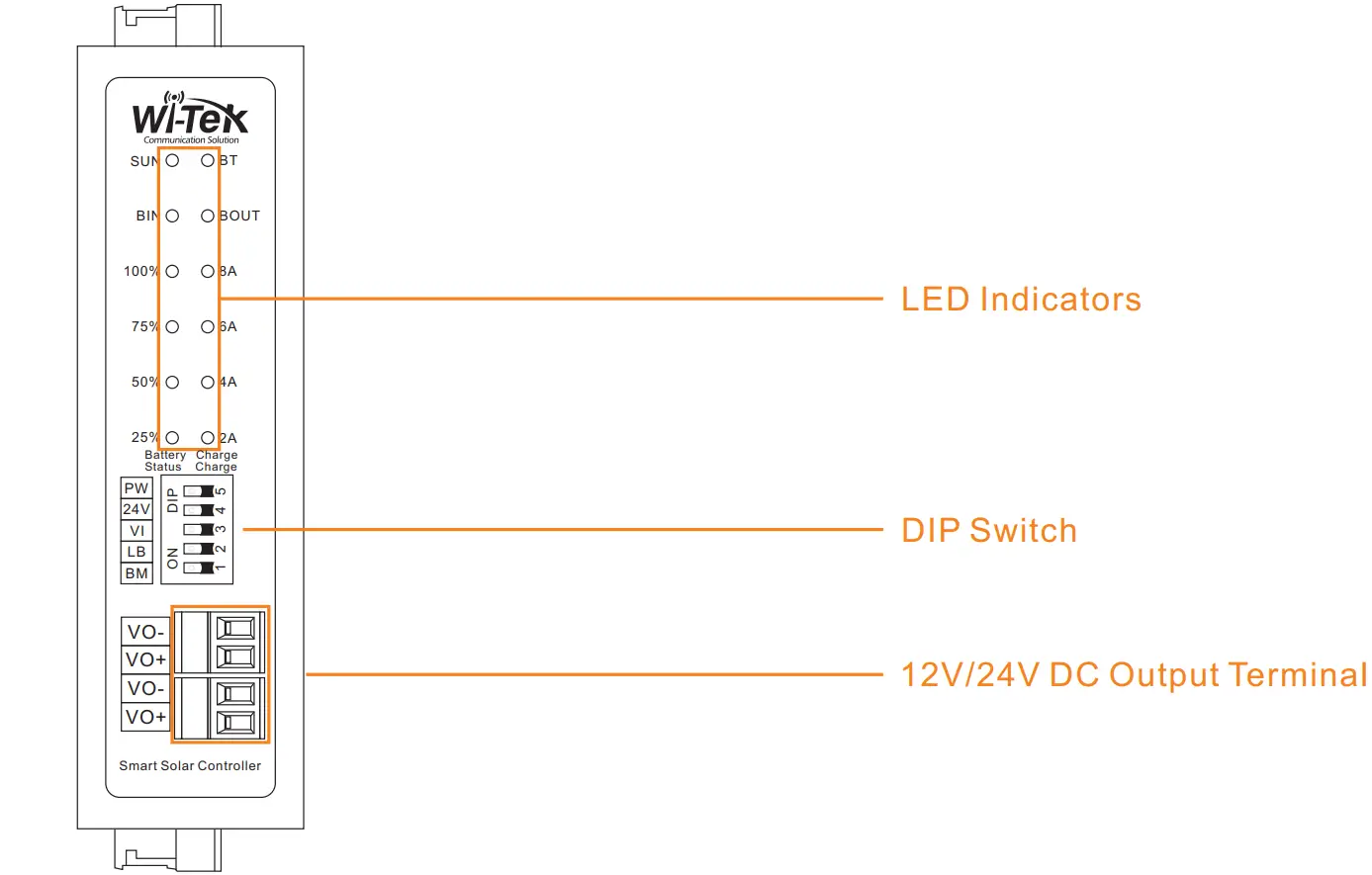
Front Panel
Top Side Panel
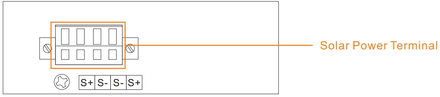
Bottom Side Panel

Note
| VO+: DC output positive electrode VO-: DC output negative electrode BT+: Battery positive electrode | BT-: Battery negative electrode S+: Solar power positive electrode S-: Solar power negative electrode |
Product Specifications
| Products | WI-PS301-UPS |
| Product Terminals | 2 x solar input terminals |
| 1 x battery input terminal | |
| 2 x DC output terminals | |
| 1 x temperature sensor terminal | |
| Max Charge Current | 8A |
| Solar Type | 12-24V 400W input (Open Circuit Voltage 18V~32V) |
| Battery type | 12V lead-acid battery |
| 12.6V/14.8V lithium battery | |
| Power Output | 12V Max 5A(Optional) |
| 24V Max 3A(Optional) |
| LED Indicators | ||
| SUN: Solar power | Solid on | The solar power on is normal |
| Off | The solar power is off or failed | |
| BIN: Battery charge | Solid on | The battery is charging |
| Off | No battery is charging or battery is failed | |
| BOUT: Battery discharge | Solid on | The battery is discharging |
| Off | No battery is discharging or battery is failed | |
| BT: Battery Status | Solid on | Battery is connected |
| Blink | Battery is disconnected or failed | |
| 25%/50%/75%/100% | Solid on | Display battery current capacity |
| 2A/4A/6A/8A | On | Display battery charging current |
| DIP Switch | ||
| PW: Power | To the left | Turn on the solar solar controller |
| To the right | Turn off the solar power | |
| 24V | To the left | The VO terminals with 24V max 3A output |
| To the right | The VO terminals with 12V max 5A output | |
| VI | To the left | Option DC input |
| To the right | Option solar power input | |
| LB: Lithum battery | To the left | 14.8V 100Ah lithum battery, max charge current 8A |
| To the right | 12.6V 100Ah lithum battery, max charge current 8A | |
| BM | To the left | Choose the 12V 100Ah lithum battery input, max charge current 8A |
| To the right | Choose the 12V 100Ah lead-acid battery, max charge current 8A | |
Note: Support 12V (18-32v) solar plate, maximum power input 200W
DIP Switch
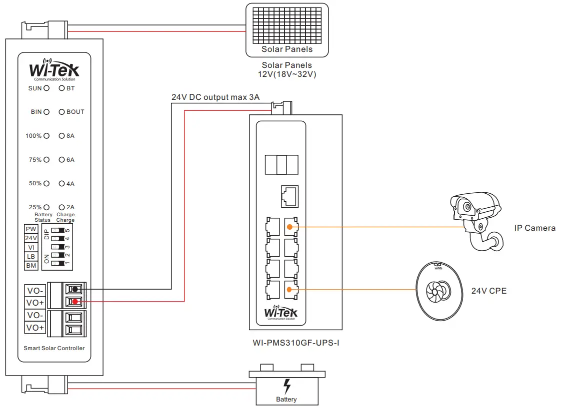
Step 1: Adjust the DIP switch (e.g. 12.6V lithum battery, 24V DC output)
Before installation, ensure that the device is powered off Option the 12V/24V DC output via DIP switch manually. Solar energy must be combined with battery use to start the device
Step 2: Hook up the 12V solar panel to S terminals, positive to positive, negative to negative
Step 3: Hook up the 1 2.6V lithum battery to B terminals, positive to positive, negative to negative.
Step 4: Hook up a device (e.g. WI-PMS310GF-Alien-I) which supports 24V DC in, positive to positive, negative to negative.
Step 5: Power on the solar controller via DIP switch.
|
|
|


Wireless-Tek Technology Limited
Address: Biaofang Technology Building 402, Bao’an street,
Baoan District,Shenzhen City, Guangdong, China
Website: www.wireless-tek.com
Tel:86-0755-32811290
Email: [email protected]
Technical Support: [email protected]