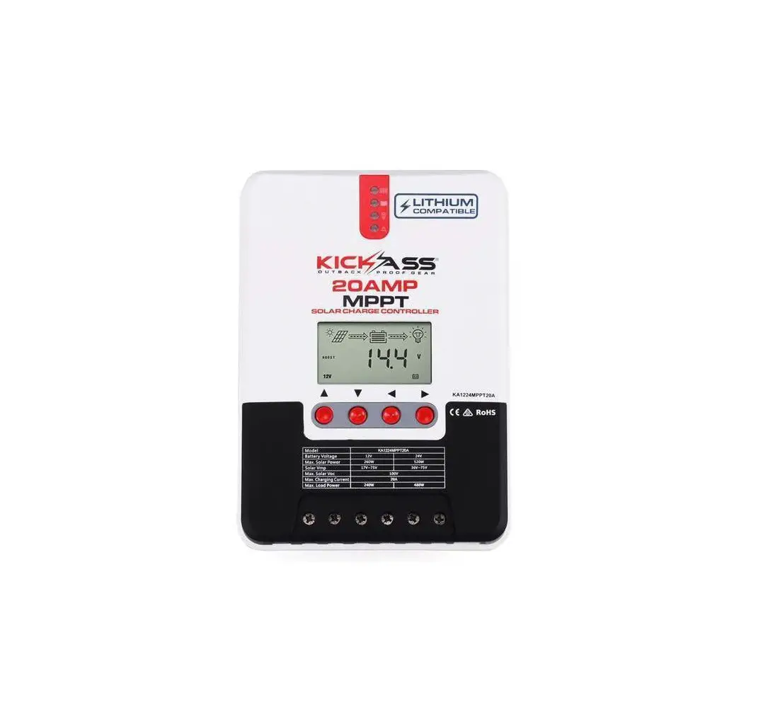
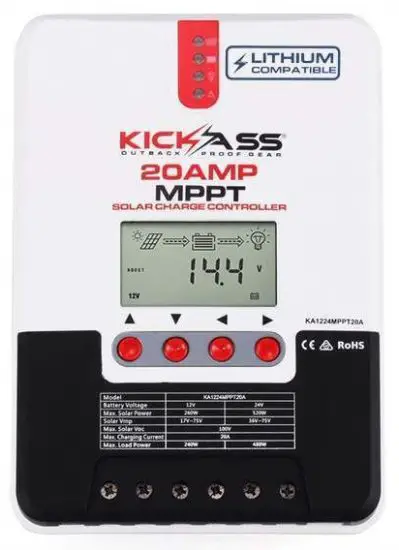
KICKASS KA1224MPPT20A Maximum Power Point Tracking Solar Charge Controller
| Model | KA1224MPPT20A | KA1224MPPT40A |
| Battery voltage | 12V/24V | |
| Max. solar panel voltage | 100V(25℃),90V(-25℃) | |
| Charging current | 20A | 40A |
PRODUCT INTRODUCTION
- This product is designed to monitor a solar panel’s generated power, tracking the highest voltage and current values in real time. This allows the charging of your battery to its highest potential, enabling the maximum power output.
- Can be used on all types of solar panels.
- The product features an easy to read LCD display allowing you to check and adjust parameters by using the direction keys below the screen. This also allows you to modify your controller to best suit your system.
- With built-in diagnostics technology, the controller is able to identify faults and display error codes for ease of troubleshooting.
Exterior Interface
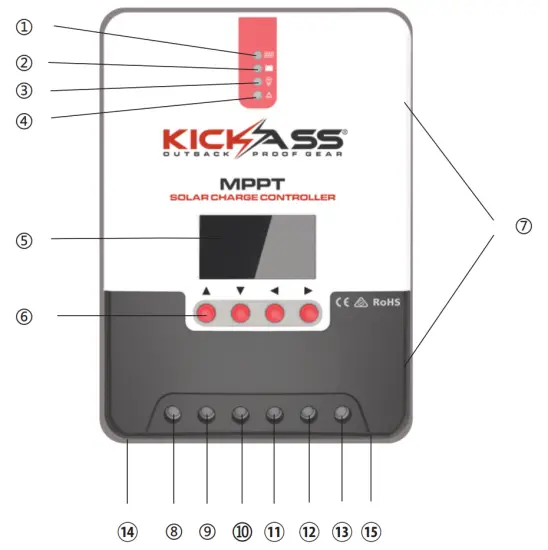
Fig. 1-1 Product appearance and interfaces
| No. | Item |
| ① | Charging indicator |
| ② | Battery indicator |
| ③ | Load indicator |
| ④ | Abnormality indicator |
| ⑤ | LCD screen |
| ⑥ | Operating keys |
| ⑦ | Installation hole |
| ⑧ | Solar panel “+” interface |
| ⑨ | Solar panel “-” interface |
| ⑩ | Battery “+” interface |
| ⑪ | Battery “-” interface |
| ⑫ | Load “+” interface |
| ⑬ | Load “-” interface |
| ⑭ | External temperature sampling interface |
| ⑮ | RJ12 communication interface |
INSTALLING CONTROLLER
- Take care when installing lead acid batteries, always wear correct safety equipment.
- Keep terminals protected from foreign metal objects to ensure terminals don’t short.
- Make sure battery is sufficiently ventilated.
- Keep battery away from open flames.
- Make sure battery is protected from direct sunlight and rain/water intrusion.
- Loose connections or corrosion to the terminals can cause excessive heat which may melt wiring.
- Always use insulated tools and keep hands dry when carrying out installation.
- Always follow the safety advice given by the battery manufacturer.
- Connect the controllers earth terminal to ground.
Wiring Specifications
Wiring installation must comply with with national and local electrical specifications. The wiring specifications of the battery and loads must be selected correctly to the size of the maximum output current.
See table below for correct wiring specifications:
Model | Rated charging current | Rated discharging current | diBattery wire2) ameter (mm | dia Load wire 2) meter (mm |
ML2420 | 20A | 20A | 5 mm 2 | 5 mm 2 |
| ML2440 | 40A | 20A | 10 mm2 | 5 mm 2 |
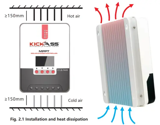
Installation and Wiring
![]() Risk of explosion! Never install the controller and battery together in a sealed environment where battery gas may accumulate.
Risk of explosion! Never install the controller and battery together in a sealed environment where battery gas may accumulate.
![]() Solar panels connected in series can produce a high voltage.
Solar panels connected in series can produce a high voltage.
Always disconnect battery whilst connecting any wiring to controller.
![]() When installing controller, make sure it is in a well ventilated area (see fig 2.1)
When installing controller, make sure it is in a well ventilated area (see fig 2.1)
PRODUCT OPERATION AND DISPLAY
CHOOSING AN INSTALLATION SITE
Keep controller away from direct sunlight or high temperatures. This will ensure that you get the maximum efficiency from your controller. Make sure area is well ventilated and away from any moisture.
MOUNTING THE CONTROLLER
Using the template provided, mark 4 holes on flat surface area intended for controller. Screw into flat surface and line up mounting holes on controller and hang controller.
BEFORE OPERATION
Make sure all connections are tight, secure and that all fuses and circuit breakers are ok.
If the LCD screen fails to turn on, remove fuse from battery and check that all connections have been made correctly. Once LCD screen turns on manually test that the load is switching on and off.
![]() When controller is charging, always disconnect the load before disconnecting your battery. This will save your controller from any possible damage.
When controller is charging, always disconnect the load before disconnecting your battery. This will save your controller from any possible damage.
![]() Within 10 minutes after the controller stops charging, reversely connecting battery will result in damage to the controller.
Within 10 minutes after the controller stops charging, reversely connecting battery will result in damage to the controller.
![]() Never connect an inverter, fridge, or other accessory requiring consistent, reliable power directly to the load side of the controller. Always connect your inverter and accessories directly to your battery, fused appropriately.
Never connect an inverter, fridge, or other accessory requiring consistent, reliable power directly to the load side of the controller. Always connect your inverter and accessories directly to your battery, fused appropriately.
LED Indicators
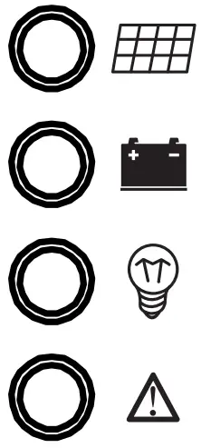 |  | PV array indicator | Indicating the controller’s current charging mode. |
 | BAT indicator | Indicating the battery’s current state. | |
 | LOAD indicator | Indicating the load’s On/ Off and state. | |
 | ERROR indicator | Indicating whether the controller is functioning normally. |
PV array indicator:
| No. | Graph | Indicator state | Charging state |
| ① |  | Steady on | MPPT charging |
| ② |  | Slow flashing (a cycle of 2s with on and off each lasting for 1s) | Boost charging |
| ③ |  | Single flashing (a cycle of 2s with on and off lasting respectively for 0.1s and 1.9s) | Floating charging |
| ④ |  | Quick flashing( a cycle of 0.2s with on and off each lasting for 0.1s) | Equalizing charging |
| ⑤ | Double flashing a cycle of 2s with on for 0.1s, off for 0.1s, on again for 0.1s, and off again for 1.7s) | Current-limited charging | |
| ⑥ | Off | No charging |
BAT indicator:
| Indicator state | Battery state |
| Steady on | Normal battery voltage |
| Slow flashing (a cycle of 2s with on and off each lasting for 1s) | Battery over-discharged |
| Quick flashing(a cycle of 0.2s with on and off each lasting for 0.1s) | Battery over-voltage |
LOAD indicator:
| Indicator state | Battery state |
| Off | Load turned off |
| Quick flashing (a cycle of 0.2s with on and off each lasting for 0.1s) | Load overloaded/ short-circuited |
| Steady on | Load functioning normally |
![]() ERROR indicator:
ERROR indicator:
| Indicator state | Battery state |
| Off | Load turned off |
| Quick flashing (a cycle of 0.2s with on and off each lasting for 0.1s) | Load overloaded/ short-circuited |
| Steady on | Load functioning normally |
Key Operations
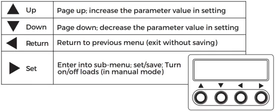
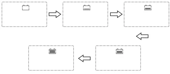
LCD Startup and Main Interface
Startup interface
During startup, the 4 indicators will first flash successively, and after self-inspection, the LCD screen starts and displays the battery’s voltage level which will be either a fixed voltage selected by the user or a voltage automatically recognized.
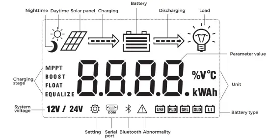
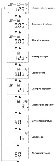
Main interface
Load Mode Setting Interface
Load modes introduction
This controller has 5 load operating modes which will be described below:
| NO. | MODE | DESCRIPTION |
| 0 | Solar Controlled (Switched based on solar state) | 5 minutes after sunlight is no longer present, the load will be switched on. The load will remain on until 1 minute after sunlight returns. |
| 1-14 | Solar Controlled + Duration | 5 minutes after sunlight is no longer present, the load will be switched on. |
| (Switched based on solar state and mode 1-14) | The load will then remain on for a period of hours specified by the mode number – ie. mode 2 = 2 hours, before switching off. | |
| 15 | Manual Mode | Load output is switched manually using arrow keys on controller. |
| 17 | Constant Power Mode | Load output remains powered on continuously. |
3.4.2 LOAD MODE ADJUSTMENT
Press the set key until the load mode screen appears,then press and hold the set key to enter press the up and down key to desired setting then press and hold the set key to save and exit.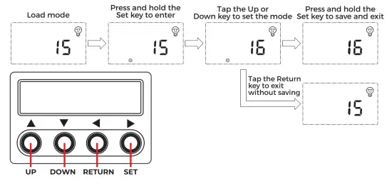
PRODUCT PROTECTION AND MAINTENANCE
Waterproof
Waterproof level: IP32
Battery reverse polarity protection
If the battery is connected in reverse the controller will not turn on, as to protect the controller from component damage.
Solar input high voltage protection
If the solar panel array voltage is too high, the controller will automatically shut down
Solar input short circuit protection
If the solar panel has a short circuit, the controller will stop working until the short is rectified.
The controller will then start working normally again.
Solar panel reverse polarity protection
If the solar panel is reversely connected, the controller will stay illuminated however there will be no power fed to the battery The controller will return to normal operation once the wiring has been corrected.
Load overpower protection
When the load power exceeds the rated power value, the load will enter into delay protection.
Load short circuit protection
If the load is short circuited, the controller will protect the load by shutting it down this can happen 5 times per day without affecting the controller.
Reverse charging protection at night
This function will protect the battery from discharging through the solar panel at night.
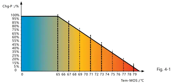
Over temperature protection
System Maintenance
To maintain the controller’s performance it is recommended that the following maintenance be carried out.
- Make sure there is enough air flow around and behind controller
- Ensure cooling fins are free of dirt or debris.
- Check for any exposed wiring between solar panel and battery and also check the load if applicable.
- Check that indicators are working correctly and check for fault codes in data analysis page, repair faults if recorded
- Check all terminal screws are tight and that there is no corrosion on terminals and wirin
- If the lightning arrestor has lost its efficiency replace with a new one in a timely manner.
Abnormality Display
| No. | Error display | Description | LED indication |
| 1 | EO | No abnormality | ERROR indicator off |
| 2 | E1 | Battery over-discharge | BAT indicator flashing slowly ERROR indicator steady on |
| 3 | E2 | Battery over-voltage | BAT indicator flashing quickly ERROR indicator steady on |
| 4 | E3 | Battery under-voltage warning | ERROR indicator steady on |
| 5 | E4 | Load short circuit | LOAD indicator flashing quickly ERROR indicator steady on |
| 6 | E5 | Load overloaded | LOAD indicator flashing quickly ERROR indicator steady on |
| 7 | E6 | Over-temperature inside controller | ERROR indicator steady on |
| 8 | E7 | Battery over temperature (E7 and E16 are different in that charging and discharging have separate upper limit protection temperature) | ERROR indicator steady on |
| 9 | E8 | Solar array overloaded | ERROR indicator steady on |
| 11 | E10 | Solar array over-voltage | ERROR indicator steady on |
| 12 | E13 | Solar array reverse polarity | ERROR indicator steady on |
| 13 | E15 | Battery not connected or lithium battery feed protection | ERROR indicator steady on |
| 14 | E16 | Battery over temperature (E7 and E16 are different in that charging and discharging have separate upper limit protection temperature) | ERROR indicator steady on |
| 15 | E18 | BMS over-current protection | ERROR indicator steady on |
| 16 | E17 | Over-temperature inside controller | ERROR indicator steady on |
| 17 | E20 | Battery reverse polarity | ERROR indicator steady on |
PRODUCT SPECIFICATION PARAMETERS
Electric Parameters
| Parameter | Value | |
| Model | KA1224MPPT20A | KA1224MPPT40A |
| System voltage | 12V/24VAuto | |
| No-load loss | 0.7 W to 1.2W | |
| Battery voltage | 9V to 35V | |
| Max. solar input voltage | 100V(25℃) 90V(-25℃) | |
| Max. power point voltage range | Battery Voltage+2V to 75V | |
| Rated charging current | 20A | 40A |
| Rated load current | 20A | |
| Max. capacitive load capacity | 10000uF | |
| Max. photovoltaic system input power | 260W/12V 520W/24V | 520W/ 12V 1040W/24V |
| Conversion efficiency | ≤98% | |
| MPPT tracking efficiency | >99% | |
| Temperature compensation factor | -3mv/℃/2V(default) | |
| Operating temperature | -35℃ to +45℃ | |
| Protection degree | IP32 | |
| Weight | 1.4Kg | 2Kg |
| Communication method | RJ12 | |
| Altitude | ≤ 3000m | |
| Product dimensions | 210*151*59.5mm | 238*173*72.5mm |
Battery Type Default Parameters (parameters set in monitor software)
PLEASE NOTE: you can access very basic user setup without bluetooth module but to access all will need the module or remote screen
| Parameters cross-reference table for different types of batteries | |||||
| Voltage to set Battery type | Sealed lead-acid battery | Gel lead-acid battery | Open lead-acid battery | Li Battery | User (self-customized) |
| Over-voltage cut-off voltage | 16.0V | 16.0V | 16.0V | —— | 9~17V |
| Equalizing voltage | 14.6V | —— | 14.8V | —— | 9~17V |
| Boost voltage | 14.4V | 14.2V | 14.6V | 14.4V | 9~17V |
| Floating charging voltage | 13.8V | 13.8V | 13.8V | —— | 9~17V |
| Boost return voltage | 13.2V | 13.2V | 13.2V | —— | 9~17V |
| Low-voltage cut-off return voltage | 12.6V | 12.6V | 12.6V | 12.6V | 9~17V |
| Under-voltage warning return voltage | 12.2V | 12.2V | 12.2V | —— | 9~17V |
| Under-voltage warning voltage | 12.0V | 12.0V | 12.0V | 11.1V | 9~17V |
| Low-voltage cut-off voltage | 11.1V | 11.1V | 11.1V | —— | 9~17V |
| Discharging limit voltage | 10.6V | 10.6V | 10.6V | —— | 9~17V |
| Over-discharge time delay | 5s | 5s | 5s | —— | 1~30s |
| Equalizing charging duration | 120 minutes | —— | 120 minutes | 0~600 minutes | |
| Equalizing charging interval | 30 days | 0 days | 30 days | —— | 0~250D (0 means the equalizing charging function is disabled) |
| Boost charging duration | 120 minutes | 120 minutes | 120minutes | —— | 10~600 minutes |
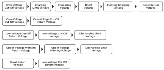
When selecting User, the battery type is to be self-customized, and in this case, the default system voltage parameters are consistent with those of the sealed lead-acid battery. When modifying battery charging and discharging parameters, the following rule must be followed:
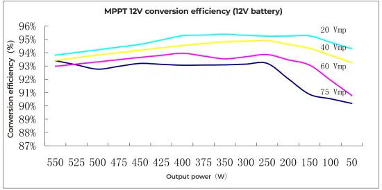
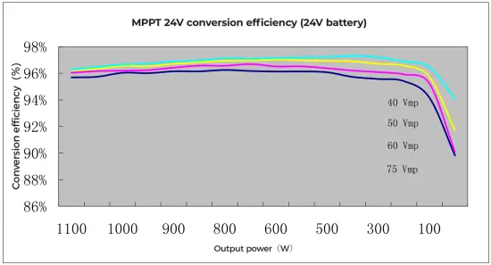
6. CONVERSION EFFICIENCY CURVE
6.1 12V System Conversion Efficiency
6.2 24V System Conversion Efficiency
7. PRODUCT DIMENSIONS
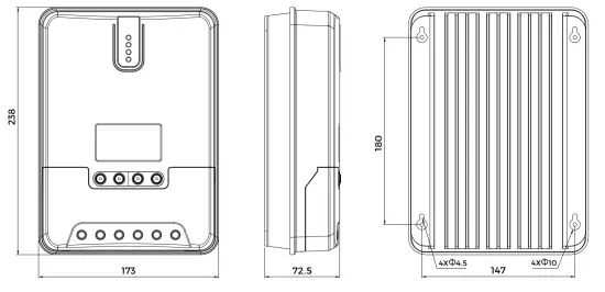
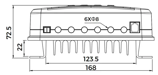
KA1224MPPT40A
Product dimensions:238*173*72.5mm
Hole positions:180*147mm
Hole diameter:Φ3mm
Applicable wire: max. 8 AWG
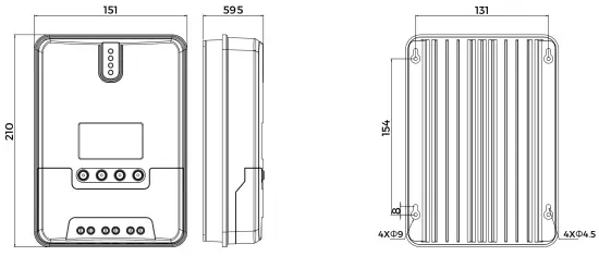
KA1224MPPT20A
Product dimensions:210*151*59.5mm
Hole positions:154*131mm
Hole diameter:Φ3mm
Applicable wire: max. 8 AWG


 Solar Mppt Charge Controller User Manual")


