
Ditec 0DT829 Traffic C
Ditec Traffic C – Traffic CM
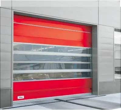
The Ditec Traffic C – Traffic CM is a motorized sliding door system designed for pedestrian access in commercial and industrial settings. It operates on a 230 V or 400 V power supply and comes with an inverter for smooth and reliable operation.
Product Information
- Power supply: 230 V or 400 V
- Inverter included for reliable operation
- Metal construction for durability and strength
- Motorized sliding door for pedestrian access
- Designed for commercial and industrial settings
Usage Instructions
The Ditec Traffic C – Traffic CM is a motorized sliding door system that requires professional installation. The following instructions are provided as a general overview of the installation process:
- Secure vertical posts in place using appropriate hardware.
- Install crossbar and secure in place.
- Install door panels and counterweights.
- Connect power supply and inverter according to manufacturer instructions.
- Program the system using the provided menu options.
Note: These instructions are for guidance only. Always refer to the manufacturer’s instructions for detailed and accurate installation and usage instructions.
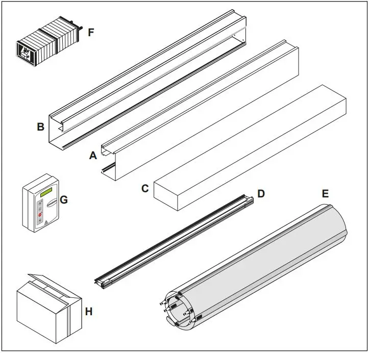
LISTE DES COMPOSANTS
| Référence | Description | Quantité |
| A | Colonne Gauche | 1 |
| B | Colonne Droite | 1 |
| C | Arbre d’enroulement | 1 |
| D | Bourrelet de sécurité | 1 |
| E | Tablier modulaire | 1 |
| F | Contrepoids | 1 |
| G | Armoire de commande | 1 |
| H | Boîte accessoires | 1 |
GENERAL SAFETY PRECAUTIONS
- This installation manual is intended for professionally competent personnel only.
- The installation, the electrical connections and the settings must be completed in conformity with good workmanship and with the laws in force.
- Read the instructions carefully before beginning to install the product. Incorrect installation may be a source of danger. Packaging materials (plastics, polystyrene, etc) must not be allowed to litter the environment and must be kept out of the reach of children for whom they may be a source of danger. Before beginning the installation check that the product is in perfect condition.
- Do not install the product in explosive areas and atmospheres: the presence of flammable gas or fumes represents a serious threat to safety.
- Before installing the door, make all the structural modifications necessary in order to create safety clerance and to guard or isolate all the compression, shearing, trapping and general danger areas.
- Check that the existing structure has the necessary strength and stability.
- The safety devices must protect against compression, shearing, trapping and general danger areas of the motorized door.
- Display the signs required by law to identify danger areas. Each installation must bear a visible indication of the data identifying the motorised door.
- Before connecting to the mains check that the rating is correct for the destination power requirements.
- A multipolar isolation switch with minimum contact gaps of 3 mm must be included in the mains supply.
- Check that upstream of the electrical installation there is an adequate differential switch and a suitable circuit breaker. Ensure that the motorised door has an earth terminal in acwireance with the safety adjustements in force.
- The manufacturer of the door declines all responsability in cases where components which are incompatible with the safe and correct operation of the product only original spare parts must be used or whenever modifications of any nature are made that have not been specifically authorised by the manufacturer.
- For repairs or replacements of products only Ditec original spare parts must be used.
- The fitter must supply all information corcerning the automatic, the manual and emergency operation of the motorised door or gate, and must provide the user the device with the operating instructions.
Optional accessory
T Safety Top
T T Safety Top T
All right reserved
All data and specifications have been drawn up and checked with the greatest care. The manufacturer cannot however take any responsibility for eventual errors, ommisions or incomplete data due to technical or illustrative purposes.
OVERVIEW
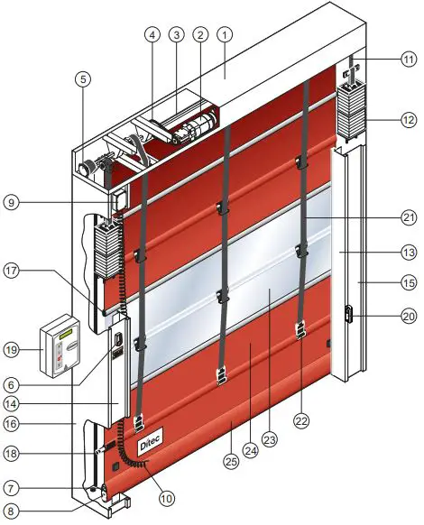
- Box
- Gear motor K10
- Winding shaft
- Transmission chain
- Counterweight belt drum
- Manual release lever
- Safety edge aluminium profile
- Safety edge rubber profile
- Safety edge connection box
- Safety edge connection cable
- Counterweight belt
- Modular counterweight
- Right-hand column cover
- Left-hand column cover
- Right-hand column
- Left-hand column
- Curtain aluminium profiles
- Curtain reinforcing tube
- Control panel
- Photocell LAB4
- Curtain lifting belt
- Curtain belt attachment
- Transparent section
- Polyester section
- Safety edge protective pocket
TECHNICAL CHARACTERISTICS
CONTROL PANEL TRIPHASE (49E)
- Power supply voltage ………….400 V triphase 50/60 Hz
- Line sizing ……………………………………………………… 6 A
- Auxiliary control power voltage…………………….24V
- Motor rating…………………………………….0,55 ÷ 1,8 KW
- Control board protection class……………………….. IP 55
- Operating temperature…………………………. – 5 + 50 °C
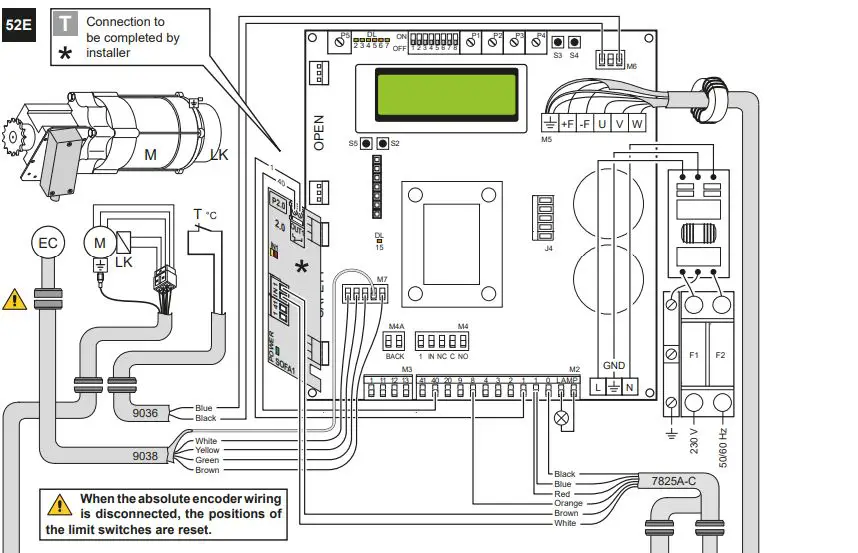
CONTROL PANEL INVERTER (52E)
- Power supply voltage ……… 230 V monofase 50/60 Hz
- Line sizing ……………………………………………………. 16 A
- Auxiliary control power voltage…………………….24V
- Motor rating…………………………………….0,55 ÷ 1,8 KW
- Control board protection class……………………….. IP 55
- Operating temperature…………………………. – 5 + 50 °C
Correctly size the line conductor cross-section by referring to the indicated absorption and taking the length and installation of the cables into account.
MECHANICAL INSTALLATION
See the relevant drawings of the mechanical installation at page. 26 – 27 (central sheet to be removed).
- Initial checks (fig.1)
- Check the size of the opening and that it corresponds to the measurements of the door supplied bearing in mind any
tolerances needed if installed within the doorway. Check that obstacles do not prevent installation. - Make sure that the mounting surfaces are level and adjust them using suitably sized spacers if necessary.
- Check the consistency of the opening structure: it must be securely anchored with brackets or plugs. If consistency is poor
or uncertain, a suitable self-supporting metal structure must be provided.
- Check the size of the opening and that it corresponds to the measurements of the door supplied bearing in mind any
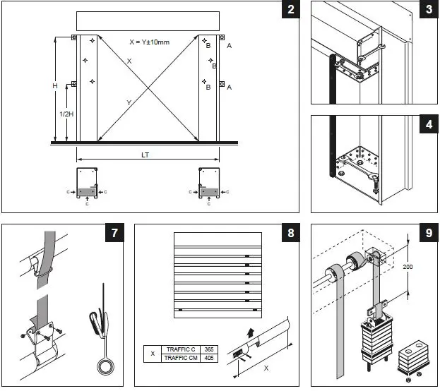
- Fixing the uprights (fig.2)
- Measure the overall dimensions of the crosspiece (LT) and mark the position of the uprights.
- Remove the covers of the uprights and fix the bases according to the marks using M8 size plugs (fig.4).
- Plumb the uprights and fix them at the indicated points (A) when using external brackets or (B) when fixing from inside
the column. M8 size plugs. Check the diagonals.
Do not drill holes in the upright near the counterweight sliding area (C).
- Assembling the crosspiece
- Remove the M8 bolts preassembled on the ends of the crosspiece.
- Lift the crosspiece using appropriate lifting equipment.
- Place the crosspiece on the uprights, reinsert the fixing bolts and tighten them (fig.3).
- For doors with PL > 4000 we recommend fastening the crosspiece in the centre (to avoid unsightly bending of the frame).
- Placing the crosspiece in position
- By referring to (fig.5A-5B), place the belt transmission wheel according to the position of the curtain. The standard installation is as shown in (fig.5A). For Ditec Traffic C, in case of position “5B” rewind the curtain on the square tube in the opposite direction.
- If the belt transmission wheel does not remain in position “5A”, remove the wheel by loosening the M8 fixing bolt and put the belt transmission wheel back into the required position. After fixing the wheel, check that it turns smoothly. Repeat the same procedure for each support.
- Assembling the curtain
- Insert the curtain in the uprights and lift it. Make sure that the belt rings are positioned correctly.
- Using the M8 bolts supplied, fasten the curtain attachment sleeve to the crosspiece (fig.6).
- Lower the curtain until it is completely unrolled. For Ditec Traffic C with a modular curtain: adjust the length of the curtain by rolling it onto the hook-up tubing if necessary.
- Unwind the curtain lifting belts and leave at least two belt turns on the winding drum. (fig.9)
- Insert the belts in the belt rings placed along the curtain. (fig.7)
- Fix the end parts of the belts using the brackets on the 1st tube. (fig.7)
- Fix the tubes using the plastic shells to prevent them sliding sideways (fig.8). The shells are already fixed on the 1st tube.
- Assembling the counterweights
- Lift the counterweight using appropriate lifting equipment (forklift truck).
- Unroll the belts and pass them around the transmission pulleys. Wind the belt around the upper pin and fix it using the special plate. Place the counterweight approximately 200 mm away from the stroke top end. (fig.9)
- Finely adjust the balance using the 4 lower counterweight elements. (fig.9)
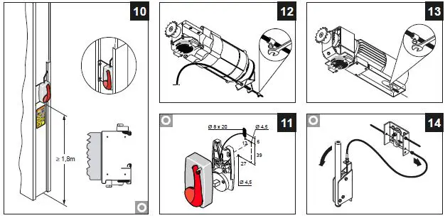
- Assembling the emergency release lever (optional)
- The emergency release lever must be assembled at least 1.8 m off the ground (fig.10, 11).
- Place the drive cable in the spaces and connect it to the gearmotor brake (fig.12, 13).
- Check that the device is operating correctly; when the lever is operated, the curtain should be free to rise.
- For Ditec Traffic CM with twin motors, the release devices are connected by way of the device shown in “figure 14”.
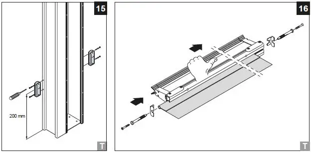
- Installing the photocells
Install the containers on the column (fig.15). For connections, follow the instructions in the photocell package. - Installing the safety edge
- Place the curtain at a height of approximately 1 m.
- Insert the safety edge into the lower pocket of the curtain (fig.16).
- Run the edge along the entire length of the curtain and place it in the exact centre of the curtain.


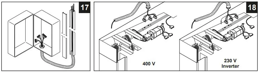
ELECTRICAL CONNECTIONS
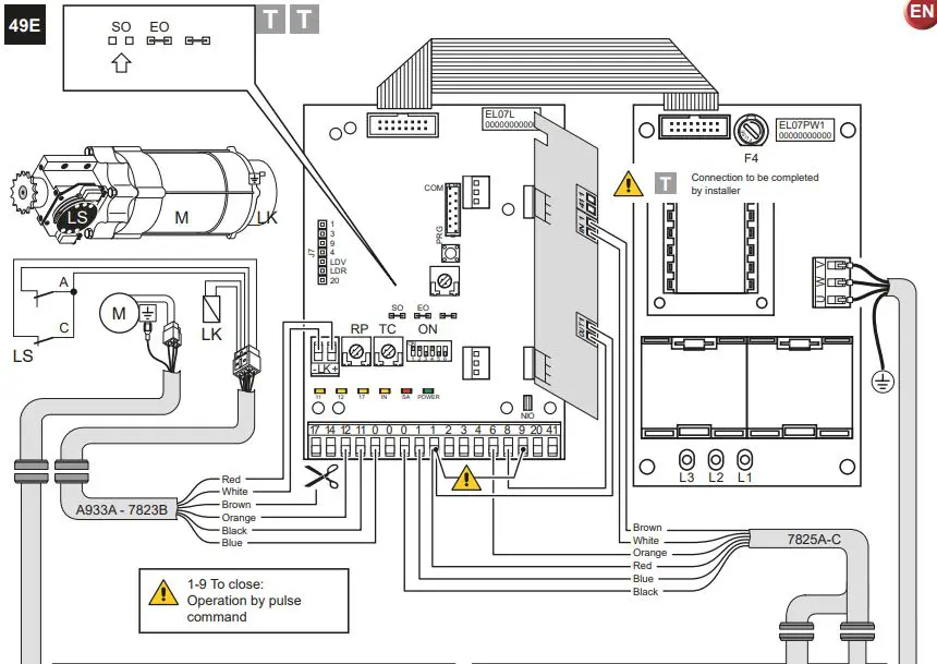
Electrical panel
Insert the cables with the pre-wired terminal boards in the housing (fig. 17) and connect them to the boards (as shown in
chap. 5). Fit the cables in the conduit and connect the connectors on the motor (fig.18).
Cabling connection on the board must be done with main power cut off, for at least 30 sec.
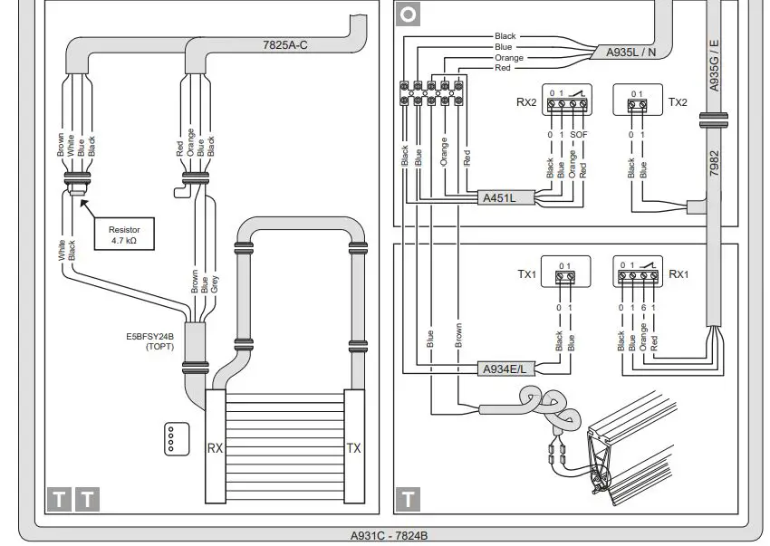
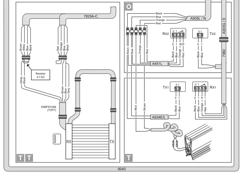
Electrical panel/motor/safety device connections
Figure 19 shows the layout of the cables supplied and their position in the door; each cable is identified by a special code on an adhesive label.
Safety photocells
Make the electrical connections as shown in (fig.19).
Make the connections in the control panel as shown in the diagrams in chap. 5.
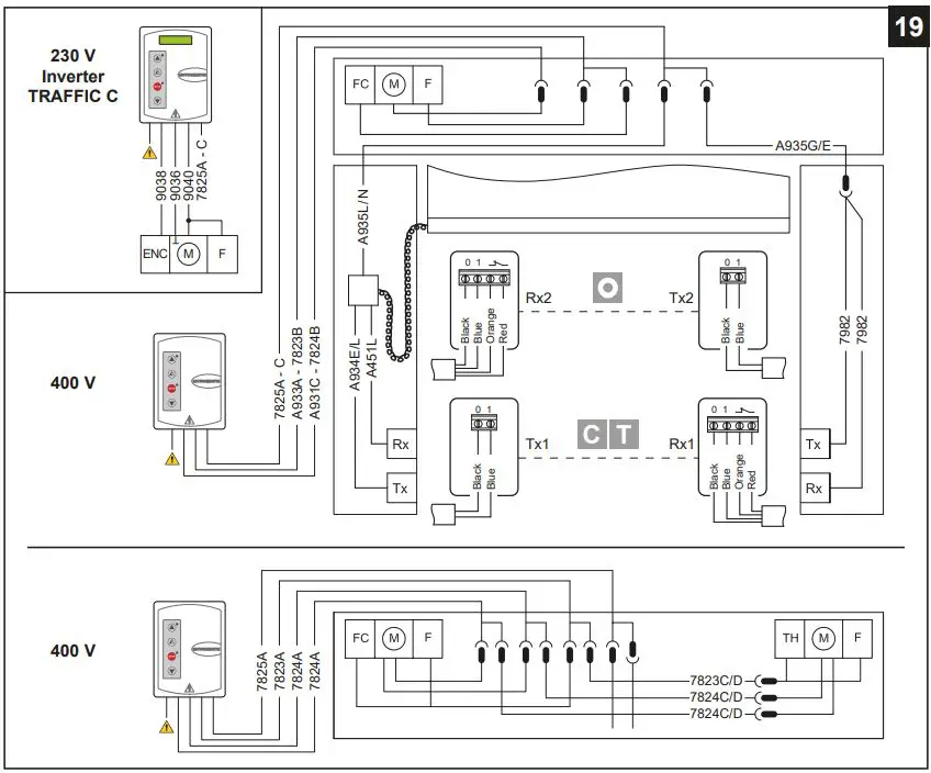
Correctly size the line conductor cross-section by referring to the indicated absorption and taking the length and installation of the cables into account.
49E ELECTRONIC CONTROL PANEL – CONNECTIONS
| INPUTS | |||||
| Command | Function | Description | |||
| 1 | 2 | N.O | Automatic closing | Permanently closing the contact enables automatic closing. | |
| 1 | 3 | N.O | Opening | With DIP1=ON the closure of the contact activates an opening operation. | |
| Step-by-step | With DIP1=OFF the closure of the contact activates an opening or closing operation in the following sequence: open-stop-close-open. Note: if automatic closing is enabled, the stop is not permanent but at a time that is set by the TC. | ||||
| 1 | 4 | N.O | Closing | The closing manoeuvre starts when the contact is closed. | |
| 1 | 6 | N.C | Reversal safety device | Opening the safety contact triggers a reversal of the movement (reopening) during a closing operation. | |
| 41 | 8 | N.C | Reversal safety device | Opening the safety contact triggers a reversal of the movement (reopening) during a closing operation. | |
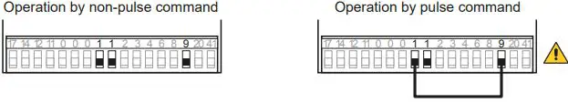
| 1 | 9 | N.C | Stop | Opening the safety contact stops the current operation. | |
| 1 | 9 | N.O | Non-pulse command | Permanently opening the safety contact enables the operation by non- pulse command. In this state, the opening (1-3/1-20) and closing (1-4) controls function only if held in the pressed position, and the automation stops when the controls are released. All safety switches, the step-by-step control and the automatic closing function are disabled. | |
| 1 | 20 | N.O | Partial opening | The closing of the contact activates a partial opening operation of the duration set with the RP trimmer. Once the automation stops, the partial opening control performs the opposite operation to the one performed before stoppage. | |
| 0 | 11 | N.C | Closure limit switch | The opening of the limit switch contact stops the closure operation. | |
| 0 | 12 | N.C | Opening limit switch | The opening of the limit switch contact stops the opening operation. | |
| 0 | 17 | N.O | Photocell limit switch | By-pass Photocell | |
SIGNALS AND SETTING
| Trimmer | Description | ||
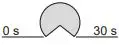 | Setting automatic closing time. From 0 to 30 s. Note: after the activation of the stop command, once contact 1-9 has closed again, the automatic closing is only activated after a total, partial or step-by-step opening command. | ||
| RP |
|
30 s | Motor partial opening adjustment. From 0 to 30 s. |
Ditec Traffic Dip-switches setting
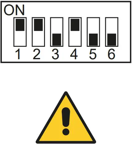
| Dip – switch | Description | OFF | ON | ||||
| DIP 1 | Control 1-3 function. | Step-by-Step | Opening | ||||
| DIP 2 | Restore automatic closing time. | Do not use | 100 % | ||||
| DIP 3 | Preflashing set at 3 s. | Disabled during opening | Enabled for both opening and closing | ||||
| DIP 4 | Application type. | Do not use | Rapid door | ||||
| DIP 5 | Dynamic brake. | Disabled | Do not use | ||||
| DIP 6 | Double speed | Disabled | Do not use | ||||
| Jumpers | Description | OFF | ON |
| SO | Reversal safety switch function. | With the automation blocked, if the contacts 41-8 are open, it is possible to activate the opening operation. | With the automation blocked, if the contacts 41-8 are open, any operation is impossible. |
| EO | Electric brake. | Do not use | Normal. |
| LED | On | Flashing |
| 24 V= power supply. | / | |
|
|
Indicates that at least one of the safety contacts is open. ( 6 – 8 – 9 ) | – Indicates the STOP operation activated by pushbutton panel PT4 (if present). – If the AUTOTEST device is installed, this indicates a safety test failure (terminal 41). – On power on, the LED flashes to indicate the number of operations performed: each rapid flash = 10000 operations each slow flash = 100000 operations |
| Activated at every command and adjustment to the dip-switch and jumper. | / | |
| Indicates that the 0-11 limit switch contact is open. | / | |
| Indicates that the 0-12 limit switch contact is open. | / | |
| Indicates that the 0-17 limit switch contact is open. (not used) | / |
| Button | LED |
|
| The green LED on indicates the presence of the 24 V=power supply. |
| the red LED on indicates that the STOP has been activated. the flashing red LED indicates that the safety devices have been activated. | |
| FUSES | |||
| ID | Value | Dimension | Circuit |
| F1 – F2 – F3 | 8A – 500V | 10.3 x 38 | Three phase line |
| F4 | 3.15A – 230V | 5 x 20 | Transformer |
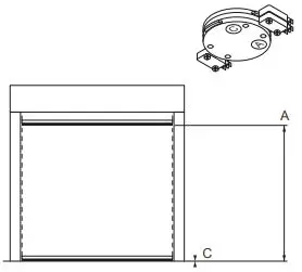
ADJUSTMENT LIMIT SWITCH
- Activate the door by pressing the appropriate buttons, and check it moves in the correct direction and If necessary, reverse the movement direction by modifying the phase sequence, adjusting the line wires upstream of the main switch.
- Carry the curtain in the closed position.
- By means of a screwdriver, turn the “C” cam until the relative micro-switch is triggered.
- Carry out the same procedure for the opening limit switch: bring the curtain to the open door position, and adjust cam “A”.
- Activate the automation to check the calibration and, if necessary, make a further adjustment.

CONTROL PANEL (INVERTER) – Connections
| INPUTS | |||||
| Command | Function | Description | |||
| 1 | 2 | NC | STOP | If on the programming menu (page 15 point 16) Contact 1-2 enabled, opening of the contact STOPS the door | |
| 1 | 3 | NO | Opening | The closure of the contact activates the opening operation. | |
| 1 | 4 | NO | Closure | The closure of the contact activates the closing operation. | |
| 41 | 40 | NC | Reversal safety contact | Opening the safety contact triggers a reversal of the movement (reopening) during the closing operation. | |
| 1 | 8 | NC | Reversal safety contact | Opening the safety contact triggers a reversal of the movement (reopening) during the closing operation. | |
| 1 | 20 | NO | Partial opening | Closing of the contact activates a partial opening operation of the duration set with the advanced menu. | |
| 1 | 11 | NC | Closing position | Opening of the contact indicates the closing position. (max. 50 mA) | |
| 1 | 13 | NC | Opening position | Opening of the contact indicates the opening position. (max. 50 mA) | |
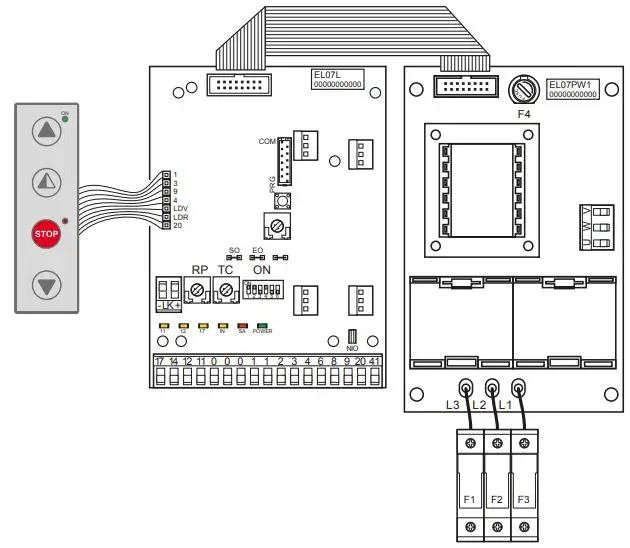
CONTROL PANEL CONNECTORS
| M2 | Safety device / Commands |
| M3 | Position signal |
| M4 | Interlock |
| M4A | Back |
| M5 | Motor / brake motor |
| M6 | Thermal motor |
| M7 | Absolute encoder |
| J4 | Brake resistance |
| OPEN | Auxiliary panel card |
| SAFETY | Auxiliary safety card |
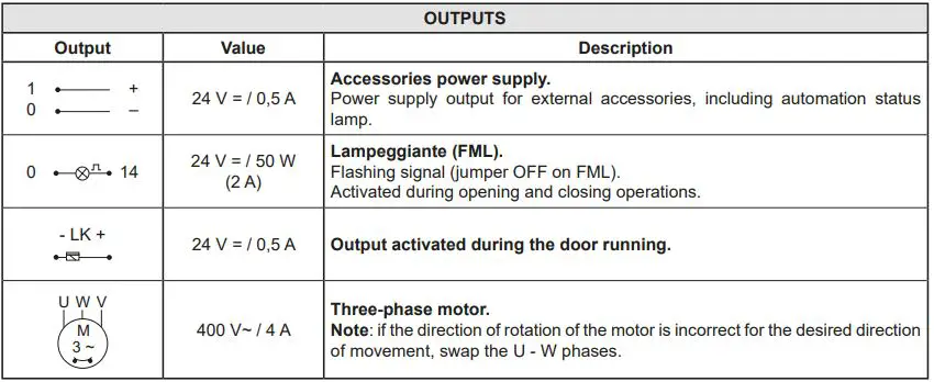
OUTPUTS
| OUTPUTS | ||
| Output | Value | Description |
|
| 24 V = / 0. 5A | Power supply to accessories. Power supply output for external accessories, including automation status lamps. |
| 230 V~ | Flashing light (FLM). Non-flashing signal (jumper ON on FML). Activated during opening and closing operations. | |
|
| 24 V = / 0.5 A | Motor electric brake. The output is active for the duration of both the opening and closing operation. |
| 230 V~ / 6 A | Three-phase motor. | |
ADJUSTMENTS AND SIGNALS
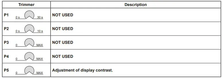
| Dip-switches | Description | OFF | ON |
| DIP 1 | Future use | – | – |
| DIP 2 | Access to advanced menu | Disabled. | Enabled |
| DIP 3 | Trimmer enabling | Disabled | Enabled |
| DIP 4 | Counter TOT: Number of operations SVC: Number of operations left until service | Disabled | Enabled |
| DIP 5 | Access to service menu | Disabled | Enabled |
| DIP 6 | Door operating data display (F working, I Bus, I peak, V Bus) | Disabled | Enabled |
| DIP 7 | Future use | – | – |
| DIP 8 | Cyclic operation menu | Disabled | Enabled |
| LED | On |
| DL2 | Closing position |
| DL3 | Deceleration |
| DL6 | Partial opening |
| DL7 | Opening position |
| DL15 | Autostart |
| Buttons | Description |
| S2 | USED FOR PROGRAMMING |
| S3 | NOT USED |
| S4 | NOT USED |
| S5 | USED FOR PROGRAMMING |
| Standard Operating | Programming Operating | |
| Button | LED | Button |
| Starts the opening operation. | – The green LED on indicates the presence of the 24 V= power supply. | Menu scrolling |
| Starts the partial opening operation. | Confirm | |
| Starts and stops the STOP operation. | – The red LED on indicates that the STOP has been activated. – The flashing red LED indicates that the safety devices have been activated. – The quick flashing red LED indicates that the service threshold has been reached | |
| Starts the closing operation. | Menu scrolling |
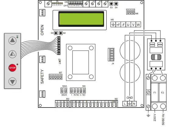
| FUSES | |||
| ID | Value | Size | Circuit |
| F1 – F2 | 12A – 500V | 10.3 x 38 | Single phase line |
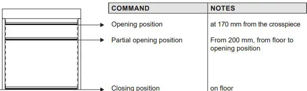
POSITION ADJUSTMENT
TROUBLESHOOTING
| Display message | Problem | Check |
| Current limit exceeded | Requested motor torque exceeds available torque. | • Reduce opening speed. • Check power supply. • Check power supply wiring. |
| Encoder battery | Absolute encoder battery flat or position read error | • Switch off the control panel, wait 3 minutes and reconnect the power supply. If the problem is not resolved, try again. • If the encoder battery message remains displayed, replace the encoder. |
| Insert brake resistance | Voltage on BUS exceeds threshold | • Switch off the control panel, wait 3 minutes and reconnect the power supply. • If the error reoccurs, check that the voltage on the BUS is lower than 360 V. |
| Max. BUS voltage | BUS voltage exceeds threshold | • Switch off the control panel, wait 3 minutes and reconnect the power supply. • Check the control panel power supply voltage. |
INSTALLATION MENU
When the control panel is switched on, after showing the messages DITEC and microprocessor and card FW VERSION, the device automatically enters the installation menu and displays the message SELECT LANGUAGE Confirm with ![]()
Remove cables from PIN 3, 4, 20 during programming
| STEP | 1st level options | 2nd level options | Menu scrolling | Notes |
| 1 | Select language |
| Confirm with: | ||
| Confirm with:
| ENGLISH | ||||
| ITALIAN | |||||
| FRANÇAIS | |||||
| DEUTCH | |||||
| ESPANOL – POLSKA CESKY – MAGYAR | |||||
| 2 | Door model |
| Confirm with: | ||
| Confirm with:
| SOFT RESET | ||||
| SECTOR RESET | |||||
| SMART PLUS | |||||
| SECTOR PLUS | |||||
| TRAFFIC C | |||||
| SMART RESET | |||||
| 3 | Position control |
| Confirm with: | ||
| Confirm with:
| ENCODER | ||||
| LIMIT SWITCH | |||||
| 4 | Calibrating positions |
| The door will move to the desired position in man present mode and at low speed.
Confirm position with: | ||
| Confirm with:
| CLOSED POSITION | ||||
| PARTIAL OPEN POS. | |||||
| OPEN POSITION | |||||
| 5 | Command mode |
| Confirm with: Selecting 1-9: if 1-9 is closed, the command mode will be impulsive, if 1-9 is open the command mode will be “dead man” | ||
| Confirm with:
| IMPULSIVE | ||||
| MAN PRESENT | |||||
| INPUT 1-9 | |||||
| 6 | CONFIRM DATA | Confirm with: |
ADVANCED MENU
The advanced menu allows you to modify the position of the limit switches which have previously been set and modify the set default parameters.
To access the Advanced Menu:
- STOP the door
- Set DIP 2 to ON
“ENCODER CALIB.”, the first item in the advanced menu, will appear on the display. - ONCE PROGRAMMING HAS ENDED, SET DIP2 TO OFF
- Remove cables from PIN 3, 4, 20 during programming
| STEP | 1st level options | Scrolling | Confirm | 2nd level options | Notes |
| 1 | Encoder Calibration |
|
| Closed position |
| The door will move to the desired position in man present mode and at low speed. All the positions (closing, partial opening, opening) must be set. |
| 2 | Photocell excluded (step present only for Reset doors) | Change value (1 unit @ 3mm) | By increasing the value, the position of the photocell by-pass is raised | |||
| 3 | Primary safety device excluded | Change value (1 unit @ 3mm) | By increasing the value, the position of the primary safety by- pass is raised | |||
| 4 | Automatic closing (default SI with T= 5 s) |
|
| YES |
| |
| NO | ||||||
| 5 | Automatic closing time | Time variant | Option available only if YES has been selected for point 4). Value ranging from 0 to 100 sec. | |||
| 6 | Command mode |
|
| Impulsive |
| Selecting 1-9: if 1-9 is closed, the command mode will be impulsive, if 1-9 is open the command mode will be “dead man” |
| Man present | ||||||
| INPUT 1-9 | ||||||
| 7 | Opening safety device |
|
| YES |
| If set to YES, the closed door that receives an opening command does not open if the photocell is activated. |
| NO | ||||||
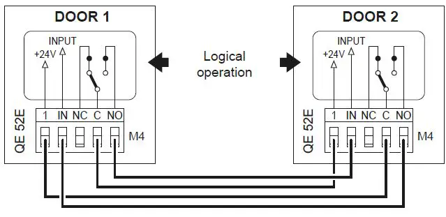
| 8 | Interlock |
|
| NO INTERLOCK |
| AIRLOCK: door 2 opens with ex- ternal command only if door 1 is closed.
INTERLOCK: door 2 opens auto- matically when door 1 has closed |
| AIRLOCK | ||||||
| INTERLOCK | ||||||
| 9 | Pre-flashing when opening (default no) |
|
| YES |
| Pre-flashing has a set time of 3 sec. |
| NO | ||||||
| 10 | Opening ramp advance | CHANGE VALUE (1 unit @ 3mm) | When the value increases, the deceleration distance when opening increases. | |||
| 11 | Opening speed in (Hz) |
|
| CHANGE VALUE |
| The setting of values that are higher than the default ones must be assessed according to door dimensions and operating conditions. |
| 12 | Closing speed in (Hz) | CHANGE VALUE | The setting of higher values must be assessed according to door dimensions and operating conditions. | |||
| 13 | Service Alarm |
|
| YES |
| |
| NO | ||||||
| RESET? | Restart the service count down | |||||
| 14 | Service thresh | CHANGE VALUE | Option available only if YES has been selected for point 14). Set value to steps of 1000 cycles Max 200,000 cycles | |||
| 15 | Enable stop 1-2 |
|
| YES |
| If set to YES, opening of the contact 1-2 STOPS the door. |
| NO | ||||||
| 16 | Brake resistance (default NO) |
|
| YES |
| Set to YES when the door is supplied with brake resistance. |
| NO | ||||||
| 17 | PARAMETER RESET | CONFIRM | Confirm to go back to the installation menu. |
ONCE PROGRAMMING HAS ENDED, SET DIP2 TO OFF
Timed opening menu
With door in STOP position and DIP 8 ON you enter the menu CYCLIC MODE. By activating this mode it is possible to set a timed opening at regular time intervals. Once the mode is set put DIP 8 OFF.
| STEP | 1st level options | Scrolling | Confirm | 2nd level options | Notes |
| 1 | CYCLIC MODE |
|
| TIMER OFF |
| Timer not active |
| TIMER ON | Timer active | |||||
| 2 | TIME UNIT |
|
| MIN. |
| Timer by minuts |
| SEC. | Timer by seconds | |||||
| 3 | OPENING TIME | 1 …200 | Set the regular time intervals | |||
| 4 | AUTO CLOS.TIME | 1….200 | Set the time during which the door remains open | |||
| 5 | TOT | VALUE | Cycle counter | |||
| 6 | RESET CYCLES | RESET? | Cycle counter reset |
When CYCLIC MODE is active, the display shows every 2 sec: TOT cycle – count down to next open/OPENING TIME
Service menu (password required)
The Service menu is used to modify the brake resistance thresholds, the overcurrent threshold and the anti-wind function when the encoder intervenes.
To access the Service menu:
- STOP the door
- Set DIP5 to ON
- Enter the PW: button sequence OPEN- OPEN- CLOSE- PARTIAL OPENING
Remove cables from PIN 3, 4, 20 during programming
| STEP | 1st level options | Notes |
| 1 | MIN BRAKING VOLT. Default 340Vdc | Threshold for partial intervention of braking resistance |
| 2 | MAX BRAKING VOLT. Default 380Vdc | Threshold for total intervention of braking resistance |
| 3 | OVERCURRENT LIMIT Default 10A | If the current on the BUS exceeds the set threshold, the door opens at half the speed to reduce absorption. |
| 4 | RAMP SLOPE DURING OPENING | Changes the slope of the deceleration ramp when opening. Default 15. (If the value is increased, the ramp distance is reduced). |
| 5 | BATTERY LEVEL | Visualizes the encoder battery charge level from 0% to 100% |
| 6 | ALARM LIST | The last 50 alarms are displayed: Overcurrent; bus voltage exceeds limit, Intervention of brake resistance, inverter overtemperature, faulty motor driver (encoder). To exit, press partial opening |
ONCE PROGRAMMING HAS ENDED, SET DIP5 TO OFF
Display messages
| MESSAGE | SITUATION | NOTES |
| Ditec | door closed waiting for command | |
| Opening of VBUS IBUS | door opening | |
| Door open – automatic closing time | Door open | |
| Closing of VBUS IBUS | door closing | |
| Input 40 closed; input 8 open | intervention of photocell | When door is moving |
| input 40 open; input 8 closed | Intervention of primary safety device | When door is moving |
| Thermal or release micro open | Intervention of safety micro on manual opening device / intervention of motor thermal switch. | |
| Opening safety device activated | photocell engaged when door is closed and door does not open | Message that only appears if the “opening safety” function is set to YES on the advanced menu (step 7). |
| Door stopped | stop command activated |
Interlock
CHECKING AND STARTING
Check of the movement direction
- Move the panel until it reaches half-way with respect to its stroke.
- Open and close the door by pressing the relative push-buttons, and check the correct movement direction.
- If required, reverse the movement direction by modifying the sequence of the phase and acting on the line cable before the main switch
TROUBLESHOOTING
DANGER
Before performing and operations and working on the electronic equipment make sure that the power supply has been disconnected
WARNING
The following instructions are for qualified and authorised personnel only. Specific laws and standards must always be complied with even when not expressly indicated.
For repair work or replacements, use only original Ditec spare parts.
| COMMAND | PROBLEM | CHECK |
| Any command with the curtain in any position | The curtain and the motor do not move | • Mains power supply or fuses F1, F2, F3 • STOP activated (“Stop” LED on push-button panel permanently on) • Motor connected to wrong terminals and/or for 400V version dip-switch in incorrect position (see page 8) • For 400V version opening (A) and closing (C) limit switches activated simultaneously (LEDs 11 e 12 on) • Motor with thermal switch activated • Manual operation safety micro activated • One of the power devices faulty (control panel, motor, motor connection cable) |
| The motor rotates in the opposite direction | • Invert the position of the two phases of the power supply line | |
| Opening command with curtain closed | The motor does not move | • Opening command not connected correctly or faulty (commands 1 – 3) • For 400V version safety device activated (Stop button LED flashing and SA LED permanently ON) with SO jumper closed • Opening limit switch(A) activated (LED 12 ON) • Closing command always activated or short-circuited |
| Closing command with curtain open | The motor does not move | • Closing command not connected correctly or faulty (commands 1 – 4) • Safety device activated (Stop button LED flashing) • Closing limit switch (C) activated (LED 11 ON) • Opening command always activated or short-circuited • Failed safety device autotest (Stop LED on push-button panel OFF) |
| Stop activated during an operation | The motor does not stop | • Stop command not working or incorrectly connected (Stop LED on push-button panel does not come on) |
| The motor stops late | • Motor brake worn or faulty | |
| Activation of a safety device during closing | Door movement is not reversed | • Safety device faulty or not connected correctly • Check earth connections. |
| Door movement does not reverse or reverses only for part of the stroke | For 400V version • Input 17 closed (LED 17 OFF) • Cam B incorrectly regulated (LED 17 OFF or comes on in an incorrect position) | |
| Automatic closure activated with curtain open | The door does not close automatically after the time set with TC | • Automatic closure not enabled correctly • Opening command always activated or short-circuited • Failed safety device autotest |
| During an operation | The curtain does not stop at the limit switch | For 400V version • Limit switch contact is short-circuited (LED 11 or LED 12 always OFF) • Mechanical fault in the limit switch (LED 11 or LED 12 always OFF) • Brake worn or faulty (LED 11 or LED 12 ON) |
| The curtain does not stop correctly at the limit switch | For 400V version • Dip-switch 5 set to OFF |
MAINTENANCE TO BE CARRIED OUT EVERY 6 MONTHS
Regular inspections should be made according to national regulations and product documentation by a Ditec trained and qualified
technician. The number of service occasions should be in accordance with national requirements and product documentation.
- Installation / Fitting
- Tighten the fitting screws of the uprights with the crosspiece
- Check the anchoring of the door to the door frame
- Motor
- Check the fixing of the motor to the relevant support
- Check the tensioning of the transmission chain
- Check the limit switches functioning and the good alignment with the cams.
- Check the brake disc wearing. If necessary replace the disc
- Check the properly manual release lever brake functioning (when applicable)
- Main Shaft / Belt
- Check the good bearing supports fixing
- Lubricate the support of the bearings by suitable grease inlet
- Check the wear and tear of the counterweight belts and the curtain. Replace the belts if necessary
- Safety Devices
- Check the good safety bar functioning
- Check the good conditions of the safety bar rubber profile
- Check the adjusting and the eventual wearing of the steel cable of the electromechanical safety edge
- Check the wearing of the mobile cable
- Check the correct operation of the safety photocells
Maintenance Plan
The table below shows the recommended interval – in months – when to replace parts during preventive maintenance
| Part | Part number | Cycles / hour | Abusive Environment (1) | ||
| <10 Low Traffic | <30 Medium Traffic | >30 High Traffic | |||
| Months | Months | Months | |||
| Limit switch group (if 400V) | 6K10GF | 36 | 24 | 12 | 12 |
| Limit switch (if 400V) | 5M | 48 | 36 | 24 | 24 |
| Brake disc | 21572 | 36 | 24 | 12 | 12 |
| Brake disc guide | 21571 | 36 | 24 | 12 | 12 |
| Safety edge coiled cable | 27795B | 36 | 24 | 12 | 12 |
| Belt counterweight and curtain | 6KTFCS | 36 | 24 | 12 | 12 |
1) Dirty or dusty environment, operating temperature near to 0°C or over 35°C, wind pressure within 20% of maximum limit.
USE INSTRUCTIONS
GENERAL SAFETY PRECAUTIONS
This user handbook is an integral and essential part of the product and must be delivered to the users. Keep this document and pass it on to any future users.
This automation is a “vertical-roll door”; it must be used for the specific purpose for which it was designed. Any other use is to be considered inappropriate and so dangerous. Assa Abloy Entrance Systems AB declines all responsibility for damage caused by improper, incorrect or unreasonable use. The device may be used by children over the age of 8 and by people with reduced physical, sensorial or mental abilities, or lack of experience or knowledge, as long as they are properly supervised or have been instructed in the safe use of the device and the relative hazards.
Cleaning and maintenance work must not be carried out by children unless they are supervised.
USE PRECAUTIONS
- Do not enter the door action area while the door is moving.
- In the event of a fault or malfunctioning, turn off the main switch. The operations of maintenance, adjustment and repair must be carried out by skilled and authorised staff.
- Each automation has its own “Installation and Maintenance handbook”, reporting the periodical maintenance plan. Please take care to check all the safety devices.
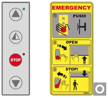
BUTTONS
 Full opening: the door opens completely. The stroke can be fixed via the end stop microswitch.
 Partial opening: the door opens partially, to a point time-regulated by the RP trimmer.
 STOP: the door stops immediately.
 Closing: the door closes completely. The stroke can be fixed via the end stop microswitch.
MANUAL RELEASE LEVER (for emergency reopening).
Warning: before using the manual lever, turn the equipment off, putting the main switch on “0”.
- When the lever is released, the brake is regularly working.
- Pulling the lever, the brake is unclamped.
- To raise manually the panel, in case of power lacking or damage, act as follows:
- pull the release lever (fig. 2), releasing the brake;
- raise the panel on open door position;
- leave the lever back (fig. 3), in order to run the brake again.
Stop the opening of the panel before the safety edge hits the crosspiece.
- Dynaco Europe n.v.
Waverstraat 21
B-9310 MOORSEL
TVA/BTW: BE 439,752,567 RCA/HRA 64232 - Tel. (+32) 53 72 98 98
- Fax (+32) 53 72 98 50
MAINTENANCE TO BE CARRIED OUT EVERY 6 MONTHS
Regular inspections should be made according to national regulations and product documentation by a Ditec trained and qualified technician. The number of service occasions should be in accordance with national requirements and product documentation.
- Installation / Fitting
- Tighten the fitting screws of the uprights with the crosspiece
- Check the anchoring of the door to the door frame
- Motor
- Check the fixing of the motor to the relevant support
- Check the tensioning of the transmission chain
- Check the limit switches functioning and the good alignment with the cams.
- Check the brake disc wearing. If necessary replace the disc
- Check the properly manual release lever brake functioning (when applicable)
- Main Shaft / Belt
- Check the good bearing supports fixing
- Lubricate the support of the bearings by suitable grease inlet
- Check the wear and tear of the counterweight belts and the curtain. Replace the belts if necessary
- Safety Devices
- Check the good safety bar functioning
- Check the good conditions of the safety bar rubber profile
- Check the adjusting and the eventual wearing of the steel cable of the electromechanical safety edge
- Check the wearing of the mobile cable
- Check the correct operation of the safety photocells
Maintenance Plan
The table below shows the recommended interval – in months – when to replace parts during preventive maintenance
| Part | Part number | Cycles / hour | Abusive Environment (1) | ||
| <10 Low Traffic | <30 Medium Traffic | >30 High Traffic | |||
| Months | Months | Months | |||
| Limit switch group (if 400V) | 6K10GF | 36 | 24 | 12 | 12 |
| Limit switch (if 400V) | 5M | 48 | 36 | 24 | 24 |
| Brake disc | 21572 | 36 | 24 | 12 | 12 |
| Brake disc guide | 21571 | 36 | 24 | 12 | 12 |
| Safety edge coiled cable | 27795B | 36 | 24 | 12 | 12 |
| Belt counterweight and curtain | 6KTFCS | 36 | 24 | 12 | 12 |
- Dirty or dusty environment, operating temperature near to 0°C or over 35°C, wind pressure within 20% of maximum limit.
Date Conter Signature Date Conter Signature
APPLICATIONS
Use: 5 (minimum 5 years of working life with 600 cycles a day)
Applications: HEAVY DUTY (for industrial and commercial access with heavy duty use).
- Service class, running times, and the number of consecutive cycles are to be taken as merely indicative having been statistically determined under average operating conditions, and cannot therefore be applied to each individual case. Reference is to the period when the product functions without the need for any extraordinary maintenance.
- Independent variables such as friction, balancing and environmental factors may substantially alter the lifespan or performance characteristics of the automatic access or parts thereof (including the automatic systems). It is the responsibility of the installer to adopt suitable safety measures for each single installation.
SOUND PRESSURE
sound pressure level LPa ≤ 70 dBa
DECLARATION OF CONFORMITY
We:
Assa Abloy Entrance Systems AB
Lodjursgatan 10
SE-261 44 Landskrona
Sweden
declare under our sole responsibility that the type of equipment with name / description:
TRAFFIC C – TRAFFIC CM Folding high speed door with counterweight
With performance levels as declared in the accompanying Declaration of Performance and the product label, and electrical drive unit as identified in the log book provided with it, is in compliance with the following directives:
2006/42/EC Machinery Directive (MD)
2014/30/EU Electromagnetic Compatibility Directive (EMCD)
2011/65/EU On the restriction of the use of certain hazardous substances in electrical and
electronic equipment (RoSH)
Harmonized European standards which have been applied:
EN 13241-1 EN 61000-6-2 EN 61000-6-3 EN 60335-1 EN 60204-1
Other standards or technical specifications, which have been applied:
EN 60335-2-103
EC type examination or certificate issued by a notified or competent body (for full address, please contact
Assa Abloy Entrance Systems AB) concerning the equipment:
CSI Spa Reg. – N° 0497
The manufacturing process ensures the compliance of the equipment with the technical file.
The manufacturing process is regularly accessed by 3rd party.
Ditec C/O Dynaco Europe n.v.
Waverstraat 21
B-9310 MOORSEL
TVA/BTW: BE 439,752,567 RCA/HRA 64232
© ASSA ABLOY


