Ditec 0DT866 52E Control Panel
Product Information
The product is a control panel for Ditec doors with K22INV and K10INV motors, equipped with limit switches group. It comes with an installation manual in French and English and optional accessories such as the Safety Confort and Safety Top.
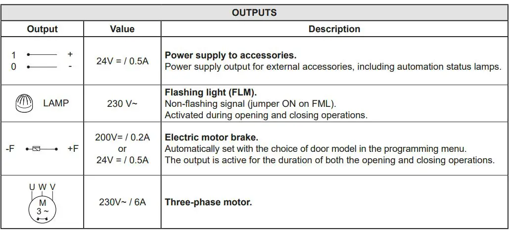
The control panel has several features such as Smart Reset, Sector Reset, Smart Plus, Sector Plus, Traffic C, and alarms. It also has input connectors for N.F. STOP, N.O Ouverture, N.O Fermeture, N.F Position de fermeture, N.F Position d’ouverture, N.F Position de ralentissement, and Activation de la fermeture avec porte de fonctionner uniquement avec un homme mort. It also has output connectors for 24 V = / 0,5 A LAMP, 230 V~ Flash clignotant (FML), Signal non intermittent, -F, +F, 200 V = / 0,2 A o, 24 V = / 0,5 A, U, W, and V.
The control panel also has trimmers and switches for adjusting the speed of opening and closing the door.
Product Usage Instructions
- Refer to the installation manual for proper installation of the control panel.
- Connect the input connectors for N.F. STOP, N.O Ouverture, N.O Fermeture, N.F Position de fermeture, N.F Position d’ouverture, N.F Position de ralentissement, and Activation de la fermeture avec porte de fonctionner uniquement avec un homme mort.
- Connect the output connectors for 24 V = / 0,5 A LAMP, 230 V~ Flash clignotant (FML), Signal non intermittent, -F, +F, 200 V = / 0,2 A o, 24 V = / 0,5 A, U, W, and V.
- Adjust the speed of opening and closing the door using the trimmers P1 and P2.
- Adjust the maximum opening time using the trimmer P3.
- Adjust the maximum closing time using the trimmer P4.
- Adjust the delay time for the safety device using the trimmer P5.
- Use the switches DIP 1 and DIP 2 for future usage.
- Refer to the manual for programming options such as Smart Reset, Sector Reset, Smart Plus, Sector Plus, Traffic C, and alarms.
GENERAL SAFETY PRECAUTIONS
This installation manual is intended for professionally competent personnel only.
Installation, electrical connections and adjustments must be performed in accordance with Good Working Methods and in compliance with the current standards.
Read the instructions carefully before installing the product. Incorrect installation could be dangerous. The packaging materials (plastic, polystyrene, etc.) should not be discarded in the environment or left within reach of children, as they are a potential source of danger.
Before installing the product, make sure it is in perfect condition. Do not install the product in explosive areas and atmospheres: the presence of inflammable gas or fumes represents a serious safety hazard. Before installing the door, make all the structural modifications necessary in order to create safety clearance and to guard or isolate all the crushing, shearing, trapping and general danger areas.
Make sure the existing structure is up to standard in terms of strength and stability. The safety devices (photocells, safety edges, emergency stops, etc.) must be installed taking into account current laws and directives, Good Working Methods, the installation environment, the system operating logic and the forces developed by the motorised door or gate.
The safety devices must protect any crushing, shearing, trapping and general hazardous areas of the door. Display the signs required by law to identify hazardous areas.
Each installation must clearly indicate the door identification data.
Before connecting the power supply, make sure the plate data correspond to those of the mains power supply. An omnipolar disconnection switch with a contact opening distance of at least 3mm must be fitted on the mains supply. Check there is an adequate residual current circuit breaker and overcurrent cutout upstream of the electrical system. Connect the door to an efficient earthing system that complies with current safety standards. The door manufacturer declines all responsibility if components not compatible with safety and good functioning are installed, or modifications of any kind are made that have not been specifically authorised by the manufacturer. Use only original Ditec spare parts when repairing or replacing products. The installer must supply all information concerning the automatic, manual and emergency operation of the motorised door or gate, and must provide the user with the operating instructions.
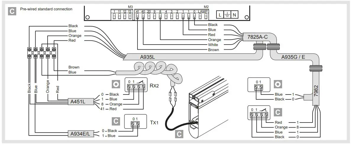
O Optional accessory
C Comfort Safety
T Top Safety
All rights reserved
The data given have been compiled and checked with the greatest care. We cannot, however, assume any responsibility for any errors, omissions or approximations due to technical or graphical requirements.
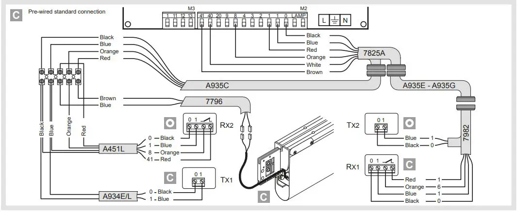
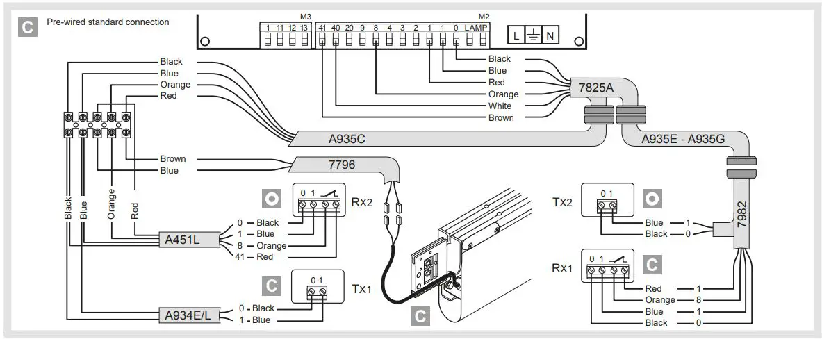
52E 1. 52E CONTROL PANEL (INVERTER) – Connections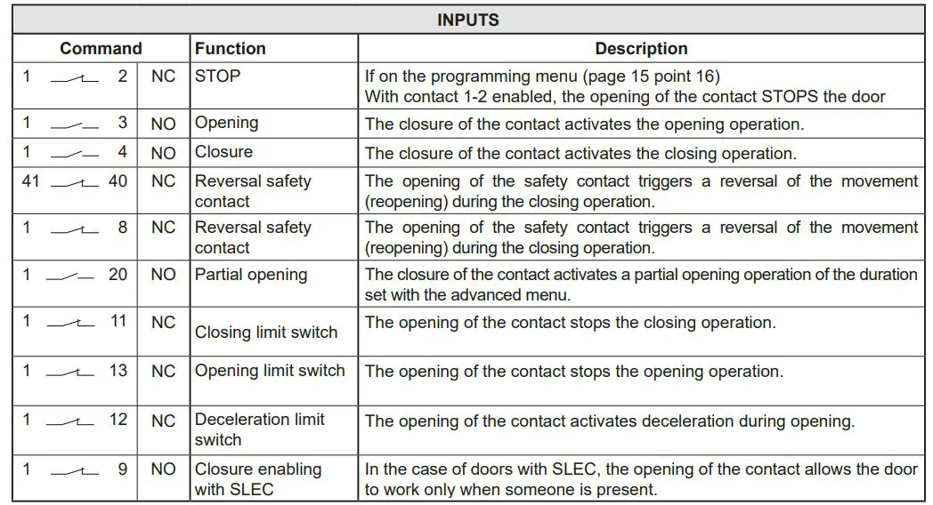
CONTROL PANEL CONNECTORS
| M2 | Safety device / Commands |
| M3 | Position signal |
| M4 | Interlock |
| M4A | Back |
| M5 | Motor / brake motor |
| J4 | Brake resistance |
| OPEN | Auxiliary panel card |
| SAFETY | Auxiliary safety card |
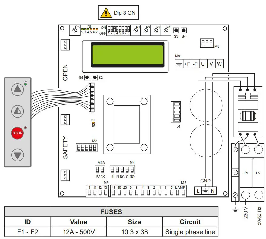
52E 2. ADJUSTMENTS AND SETTINGS
| Trimmer | Description |
P1  | Opening speed |
P2  | Closing speed |
| P3
| Deceleration during opening |
| P4
| Adjustment of deceleration during closure |
| P5
| Adjustment of display contrast. |

| Dip-switches | Description | OFF | ON |
| DIP 1 | Future use | – | – |
| DIP 2 | Access to advanced menu | Disabled | Enabled |
| DIP 3 | Trimmer enabling | Disabled | Enabled |
| DIP 4 | Counter TOT: Number of operations SVC: Number of operations left until service | Disabled | Enabled |
| DIP 5 | Access to service menu | Disabled | Enabled |
| DIP 6 | Door operating data display (F working, I Bus, I peak, V Bus) | Disabled | Enabled |
| DIP 7 | Future use | – | – |
| DIP 8 | Cyclic operation menu | Disabled | Enabled |
| LED | On |
| DL2 | Closing position |
| DL3 | Deceleration |
| DL6 | Partial opening |
| DL7 | Opening position |
| DL15 | Autostart |
| Buttons | Description |
| S2 | USED FOR PROGRAMMING |
| S3 | NOT USED |
| S4 | NOT USED |
| S5 | USED FOR PROGRAMMING |
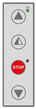
| Operating mode Standard | Programming Operating | |
| Button | LED | Button |
| Starts the opening operation. | – The green LED on indicates the presence of the 24 V= power supply. | Menu scrolling |
| Starts the partial opening operation. | Confirm | |
| Starts and stops the STOP operation. | – The red LED on indicates that the STOP has been activated. – The flashing red LED indicates that the safety devices have been activated. – The quick flashing red LED indicates that the service threshold has been reached | |
| Starts the closing operation. | Menu scrolling |
SMART RESET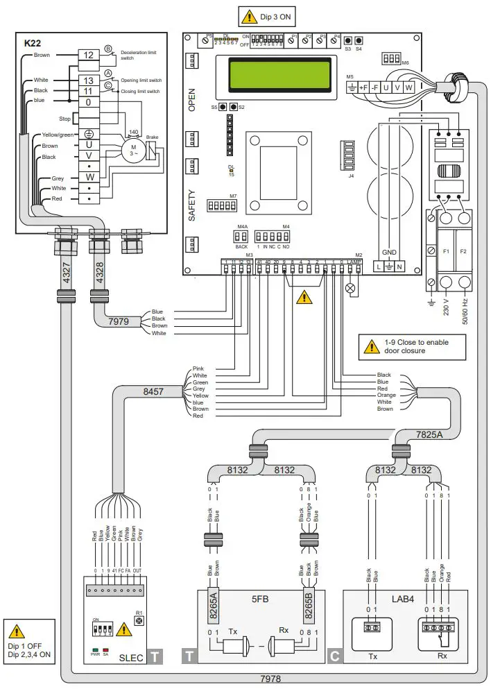
SECTOR RESET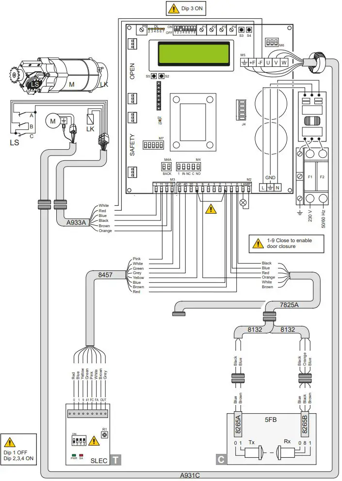
SMART PLUS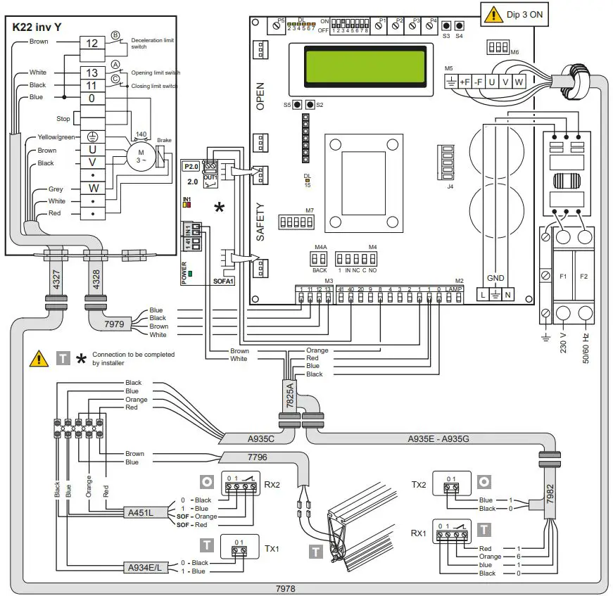
SECTOR PLUS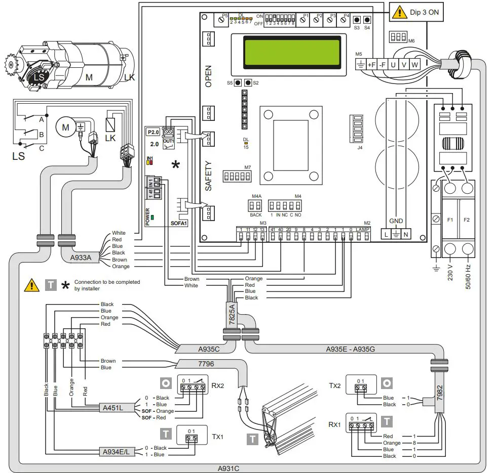
TRAFFIC C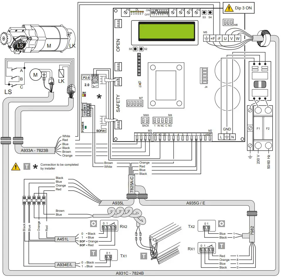
LIMIT SWITCH ADJUSTMENT
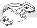
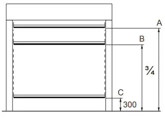
- Set the deceleration ramps at zero (P3 – P4)
- Set the limit switch (C) on the gearmotor so that the door stops about 200/300mm from its closure point.
- Set the opening limit switch (A) at the opening point.
- Set the deceleration limit switch (B) so it is triggered at about ¾ of the opening stroke.
- Set the opening and closure speeds using trimmers (P1) and (P2) respectively.
- Set the trimmers of the deceleration ramps – (P3) for opening and (P4) for closure – to ensure the door stops at its actual “open” and “closed” positions.
TROUBLESHOOTING
| Display message | Problem | Check |
| Current limit exceeded | Requested motor torque exceeds available torque. | • Reduce opening speed. • Check power supply. • Check power supply wiring. |
| Insert brake resistance | Voltage on BUS exceeds threshold | • For Sector Reset doors, connect the brake resistance and set the item on the advanced menu to “YES”. • Switch off the control panel, wait 3 minutes and reconnect the power supply. • If the error reoccurs, check that the voltage on the BUS is lower than 360 V. |
| Max. BUS voltage | BUS voltage exceeds threshold | • Switch off the control panel, wait 3 minutes and reconnect the power supply. • Check the control panel power supply voltage. |
| Stand by Encoder | Installation of a new control/ replacement control already programmed previously
Absolute Encoder not connected. | To reset the control panel follow the procedure: • DIP2 in ON • push STOP (the control panel goes in the “programmin menu” showing the data already set) • scroll the menù till the step “COMMAND MODE” and set LIMIT SWITCHES • DIP2 in OFF |
PROGRAMMING
INSTALLATION MENU
When the control panel is switched on, after showing the messages DITEC and microprocessor and card FW VERSION, the device automatically enters the installation menu and displays the message SELECT LANGUAGE.
Confirm with
Remove cables from PIN 3, 4, 20 during programming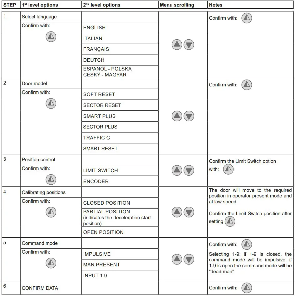
PROGRAMMING COMPLETED
The door is now programmed and operating with the set default speed values.
With the door MOVING, the voltage and current values will be displayed on the BUS.
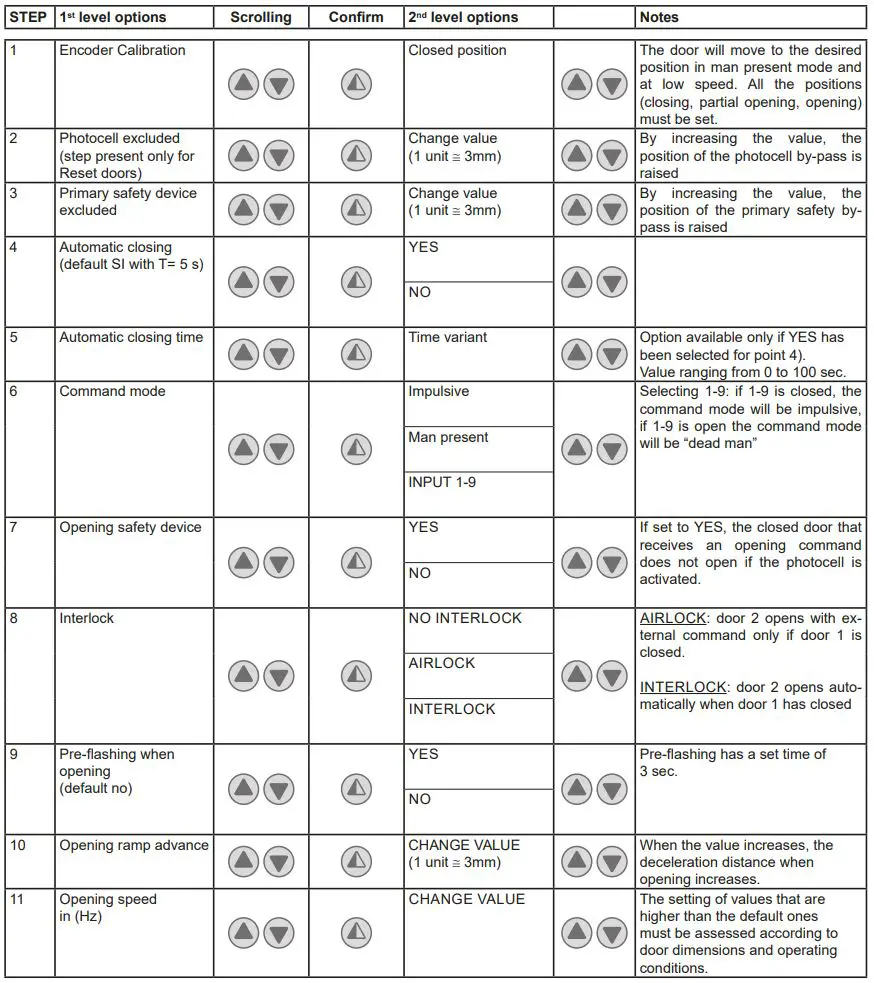
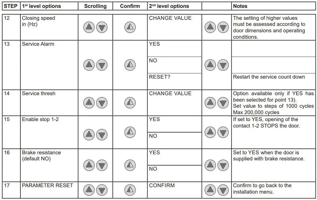
ADVANCED MENU
The advanced menu allows you to modify the position of the limit switches which have previously been set and modify the set default parameters.
To access the Advanced Menu:
- STOP the door
- Set DIP 2 to ON
“LIM. SWITCH CAL.”, the first item in the advanced menu, will appear on the display.
- ONCE PROGRAMMING HAS ENDED, SET DIP2 TO OFF
- Remove cables from PIN 3, 4, 20 during programming


ONCE PROGRAMMING HAS ENDED, SET DIP2 TO OFF
Timed opening menu
With door in STOP position and DIP 8 ON you enter the menu CYCLIC MODE. By activating this mode it is possible to set a timed opening at regular time intervals. Once the mode is set put DIP 8 OFF.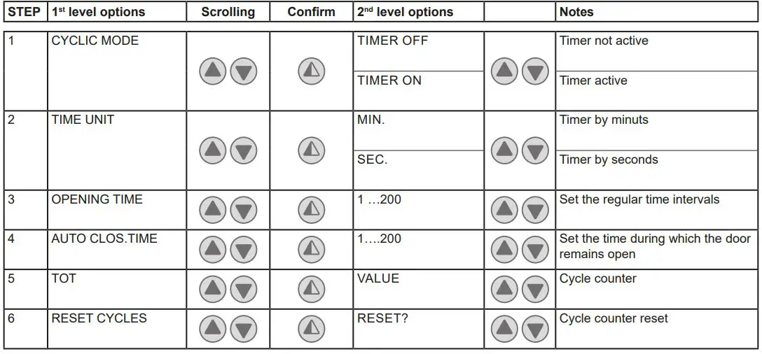
When CYCLIC MODE is active, the display shows every 2 sec:
TOT cycle – count down to next open/OPENING TIME
Service menu (password required)
To access the Service menu:
- STOP the door
- Set DIP5 to ON
- Enter the PW: button sequence OPEN- OPEN- CLOSE- PARTIAL OPENING
Remove cables from PIN 3, 4, 20 during programming
| 1 | MIN BRAKING VOLT. Default 340Vdc | Threshold for partial intervention of braking resistance |
| 2 | MAX BRAKING VOLT. Default 380Vdc | Threshold for total intervention of braking resistance |
| 3 | OVERCURRENT LIMIT Default 10A | If the current on the BUS exceeds the set threshold, the door opens at half the speed to reduce absorption. |
| 4 | RAMP SLOPE DURING OPENING | Changes the slope of the deceleration ramp when opening. Default 15. (If the value is increased, the ramp distance is reduced). |
| 5 | BATTERY LEVEL | Visualizes the encoder battery charge level from 0% to 100% |
| 6 | ALARM LIST | The last 50 alarms are displayed: Overcurrent; bus voltage exceeds limit, Intervention of brake resistance, inverter overtemperature, faulty motor driver (encoder). To exit, press partial opening |
ONCE PROGRAMMING HAS ENDED, SET DIP5 TO OFF
ALARMS
MESSAGE SITUATION NOTES
| Ditec | door closed waiting for command | |
| Opening of VBUS IBUS | door opening | |
| Door open – automatic closing time | Door open | |
| Closing of VBUS IBUS | door closing | |
| Input 40 closed; input 8 open | intervention of photocell | When door is moving |
| input 40 open; input 8 closed | Primary safety device intervention (SLEC / SAFETY EDGE) | When door is moving |
| Limit switches open | Intervention of safety microswitch on manual opening device / intervention of thermal protection on motor / opening (A) and closure (C) limit switches simultaneously active. | |
| Opening safety device activated | photocell engaged when door is closed and door does not open | Message that only appears if the “safety in open” function is set to YES on the advanced menu (step 7). |
| Door stopped | stop command activated | |
| Stand by encoder | New control panel power on / replacing control panel power on Absolute Encoder not connected. | Control panel already programmed to work with motor having absolute encoder. To reset see troubleshooting chapter. |
INTERLOCK
Ditec C/O Dynaco Europe n.v.
Waverstraat 21
B-9310 MOORSEL
TVA/BTW: BE 439,752,567 RCA/HRA 64232
© ASSA ABLOY


