THORLABS QS20 Series 2-Axis Galvo Scanners User Guide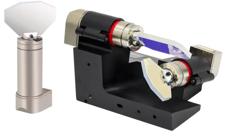
Warning Symbol Definitions
Below is a list of warning symbols you may encounter in this manual or on your device.
Symbol Description
![]() Direct Current
Direct Current![]() Alternating Current
Alternating Current![]() Both Direct and Alternating Current
Both Direct and Alternating Current![]() Earth Ground Terminal
Earth Ground Terminal Protective Conductor Terminal
 Frame or Chassis Terminal
 Equipotentiality
![]() On (Supply)
On (Supply) Off (Supply)
![]() In Position of a Bi-Stable Push Control
In Position of a Bi-Stable Push Control Out Position of a Bi-Stable Push Control
 Caution: Risk of Electric Shock
 Caution: Hot Surface
 Caution: Risk of Danger
 Warning: Laser Radiation
 Caution: Spinning Blades May Cause Harm
Safety
Safety Information
The following safety symbols may be used throughout the handbook and on the equipment itself.
![]() CAUTION
CAUTION
Caution is given when there is a possibility of damage to the product.
![]() WARNING
WARNING
Given when there is danger of injury to users.
General Warnings
![]() CAUTION
CAUTION
Excessive moisture may impair operation. Spillage of fluid, such as sample solutions, should be avoided. If spillage does occur, clean up immediately using absorbant tissue. Do not allow spilled fluid to enter the internal mechanism.
![]() WARNING
WARNING
Although the unit does not emit radiation, it does redirect laser radiation emitted from other devices.
Operators must follow all safety precautions provided by the manufacturer of any associated laser devices.
![]() WARNING
WARNING
Safety precautions should be taken to avoid exposure to laser radiation. During system shutdown or malfunction, the scanner can point the beam anywhere within its range of rotation. It is up to the user of these scanners to limit the exit aperture of the laser beam in order to provide laser safety.
- When unpacking the galvanometer, care should be taken not to damage the rotor. The rotor and bearing assemblies can be easily damaged if impacted or loaded with excessive forces. Furthermore, the galvanometer should be kept free of dirt, dust, oil, and other contaminants.
- Do not make physical contact with the galvo mirrors. If absolutely necessary, handle the mirrors with extreme care. Use finger cots or gloves before touching any mirrors or optical elements. Finger oils will damage the reflective coatings on the mirrors.
- Do not remove or adjust the mirror. Any changes to this mounting can affect the resonance and cause the system to go unstable during operation.
- When unpacking the servo drive electronics, caution should be used to protect against static electricity damage. Failure to use proper static protection may cause damage to the servo driver boards and void the manufacturer’s warranty.
- Galvanometers packaged with servo drivers (and mirrors) are factory tuned as a set. Each galvanometer is tuned to a specific a servo driver and MUST stay together as a set. For systems using more than one galvanometer and servo amplifier, the units are not interchangeable. Servo driver boards have a copy of their mating scanner serial number on the bottom.
- Servo drivers must be properly attached to a heat sink. Refer to Chapter 7: Heat Sink Requirements for proper heat sinking instructions. Failure to heat sink the servo driver could result in overheating of components, which could damage the driver and void the manufacturer’s warranty.
- Every servo driver is tuned to accept a specific input voltage range. Using input command voltages outside of this range may cause hardware damage. Thorlabs will not be responsible for damage as a result of command input voltages that exceed the specified voltage range.
- Proper voltage and ground need to be supplied prior to operation. The power supply should have sufficient voltage and current for the application. Noisy power supplies can result in poor scanner performance.
Switching power supplies can often introduce unwanted noise. - Be sure that the mirror does not collide with any other mirrors or objects.
- Your optical scanners were carefully tested and inspected before packaging. Please report any damage to your shipping company immediately.
Introduction
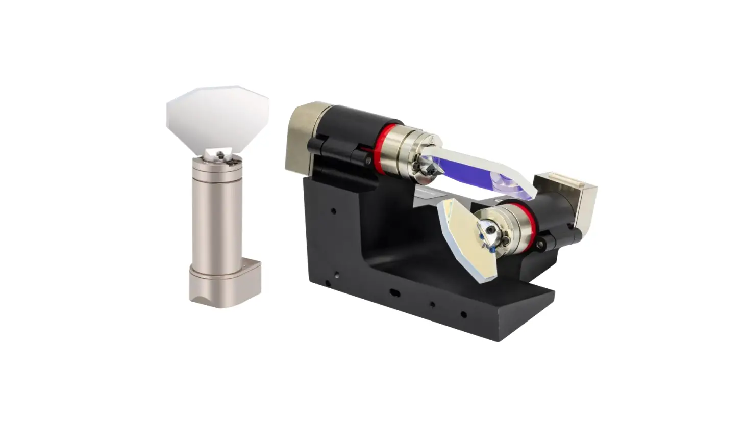
This manual covers the installation and use of Thorlabs’ QS15 & QS20 Series 1- & 2-Axis Galvanometer Scanners.
These galvo scanners are specifically designed to rotate optical scanning mirrors at a high bandwidth and then settle to a high degree of accuracy and repeatability. They are designed to carry a balanced inertial load, matched to the size of the stator and rotor combination. The exact inertia that can be driven depends on the application, which in turn specifies a speed and settling accuracy requirement.
![]() WARNING
WARNING
Safety precautions should be taken to avoid exposure to laser radiation. During system shutdown or malfunction, the scanner can point the beam anywhere within its range of rotation. It is up to the user of these scanners to limit the exit aperture of the laser beam in order to provide laser safety.
![]() CAUTION
CAUTION
This manual contains all the information necessary to install and operate the the galvo scanner. Servo drivers are factory tuned with a matched galvanometer and mirror. Do not adjust the servo driver in the field. Only factory trained service technicians should adjust any of the potentiometers on the board. If it becomes necessary to return a servo driver board to the factory, the matching galvanometer and mirror should be returned along with it. Any unauthorized attempt to adjust the servo by an untrained individual could result in serious damage to the scanner, mirror, and electronics.
![]() CAUTION
CAUTION
Galvanometer bearings are delicate and prone to damage if not handled with care. Never apply excessive axial or radial force to the galvanometer rotor. Dropping the galvanometer could damage the mirror, rotor, bearings, or position detector.
Quick Connect Guide
The instructions below serve as a quick guide. Before connecting the servo drives, please read Chapter 2 for safety precautions and refer to the servo driver manual for additional information and instructions.
- Set your dual voltage supply to the necessary output voltage range (per the driver manual) before connecting the galvanometer power cables.
- The servo drive accepts command inputs within the range of ±5 V. Inputs outside of this voltage range may damage hardware.
- After adjusting the power supplies, turn them off before making any connections to the servo drive(s).
- The servo drive(s) should be properly mounted to a sufficient heat sink.
- Galvanometers should be mounted properly to avoid mirror collisions.
- Connect the Galvanometer Position Detector & Drive (9 Pin) to the Servo Driver Board (J1). Repeat if there is more than one Galvanometer.
- Connect the Scanner Drive (black, 3 Pin) to the Servo Driver Board (J6). Repeat if there is more than one Galvanometer.
- Connect the Power Cable(s) from the Power Supply to the Servo Driver Board(s) (J7).
- Connect the Command Input Cable(s) from the function generator or host system to the servo drive board(s) (J3).
Note: Do not, under any circumstances, remove the mirror from the galvanometer. Removing and remounting the mirror changes the resonant frequency of the unit and requires re-tuning before operation.
Failure to re-tune units after mirror changes can result in hardware damage. If you need to remove the mirror in order to mount your galvanometer, please contact Thorlabs Tech Support for guidance.
Note: For systems using more than one galvanometer and servo amplifier, the galvanometer is match-tuned to a specific servo amplifier. The units are not interchangeable.
Specifications
Galvo Scanner Specs
| Item # Prefix | QS15 | QS20 | |
| Max Beam Diameter | 15 mm | 20 mm | |
| Mirror Substrate | Fused Silica | ||
| Step Response Time (0.4° Optical) | 600 µs | 650 µs | |
| Mechanical & Electrical Specifications | |||
| Rated Excursion | ±22.5° Opticala | ||
| Rotor Inertial Load | Recommended | 1.8 g·cm2 | |
| Max | 9 g·cm2 | ||
| Torque Constant | 180 000 dyne·cm/A | ||
| Coil Resistance | 3.0 Ω | ||
| Coil Inductance | 530 µH @ 1 kHz | ||
| Position Detector | |||
| Type | Optical | ||
| Linearity | 99.8% @ ±20° | ||
| Gain Drift | 50 ppm/°C | ||
| Offset Drift | 30 µrad/°C | ||
| Repeatability | 10 µrad | ||
| Output Signal (Typ.) | Differential Mode | 7.1 µA/° Optical | |
| Common Mode | 385 µA | ||
| Supply Current | 30 – 40 mA | ||
| General Specifications | |||
| Operating Temperature | 0 to 40 °C (Non-Condensing) | ||
| Storage Temperature | -10 to 50 °C | ||
| Servo Shaft Size | Ø22 mm x 50 mm | ||
Mirror Coating Specs
| Item # Suffix | -AG | -Y3 | -Y1 | -CD |
| Coating Type | Protected Silver | Hard Dielectric for Nd:YAG Laser 3rd Harmonic | Hard Dielectric for Nd:YAG Laser Fundamental | Dielectric on Metal for CO2 Laser |
| Absolute Reflectance | ≥92% (450 – 500 nm) ≥94.5% (500 – 2000 nm) ≥98% (2 – 10.6 µm) | ≥99% (355 nm) ≥80% (633 nm) | ≥98% (1064 nm) ≥80% (633 nm) | ≥99.5% (10.64 µm) ≥80% (633 nm) |
| Surface Quality (Scratch-Dig) | 40-20 | 20-10 | 40-20 | 40-20 |
Connectors
The 9-pin connector carries the two differential position detector signals (ib and ia), the AGC voltage (Oscillator Power), the two motor drive signals, and ground. These signals connect to the galvanometer connector on the servo drive board (see servo drive manual for more details).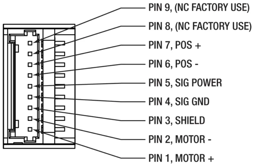
Heat Sink Requirements
![]() CAUTION
CAUTION
The servo driver board MUST be attached to an additional heat sink before applying power. Failure to provide proper heat sinking could result in damaged components and void the manufacturer’s warranty.
These galvanometers typically do not require special heat sinking. Under most operating conditions, the galvanometer’s motor will radially transfer its heat from the motor to the surrounding air. The galvanometers are mounted by clamping in the motor section such that heat generated by the galvanometer motor does not cause thermal drift in the position detector.
Temperature changes in the galvanometer environment can cause small amounts of drift in the galvanometer’s position (see specifications). It is recommended that the galvanometer(s) be operated at the most rigorous level required during the user’s application, rather than alternating between rigorous and light operation. This will ensure that the drift remains a constant offset over the course of operation.
Monitor the temperature of the galvanometer on the mid section of the galvanometer stator. The stator chassis temperature should not exceed 45 °C. If the operating temperature of the galvanometer exceeds this temperature, additional heat sink capacity will be required. This can be accomplished by blowing cool air across the motor or by clamping additional heat sinking material to the motor chassis.
Mounting Requirements
The diagram below shows the mounting surface of the galvo. If electrical isolation is required, use a mylar shim up to 0.002” thick.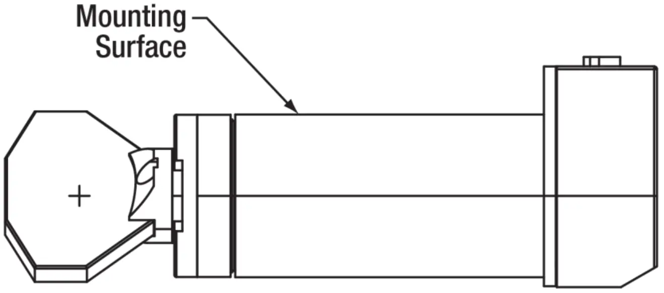
The galvanometers should be mounted in a C-type compression clamp built into a rigid structure. The mounting material most commonly used is aluminum. Ensure that the mirror can rotate through its full angular range without hitting anything.
![]() CAUTION
CAUTION
Do not over torque the mount or damage to the galvanometer may occur.
Limited Warranty
Thorlabs warrants material and production of the device, excluding the mirror coatings, for a period of 24 months starting with the date of shipment in accordance with and subject to the terms and conditions set forth in Thorlabs’ General Terms and Conditions of Sale, which can be found at:
https://www.thorlabs.com/Images/PDF/LG-PO-001_Thorlabs_terms_and_%20agreements.pdf
Regulatory
As required by the WEEE (Waste Electrical and Electronic Equipment Directive) of the European Community and the corresponding national laws, Thorlabs offers all end users in the EC the possibility to return “end of life” units without incurring disposal charges.
- This offer is valid for Thorlabs electrical and electronic equipment:
- Sold after August 13, 2005
- Marked correspondingly with the crossed out “wheelie bin” logo (see right)
- Sold to a company or institute within the EC
- Currently owned by a company or institute within the EC
- Still complete, not disassembled and not contaminated
As the WEEE directive applies to self-contained operational electrical and electronic products, this end of life take back service does not refer to other Thorlabs products, such as: - Pure OEM products, that means assemblies to be built into a unit by the user (e. g. OEM laser driver cards)
- Components
- Mechanics and optics
- Left over parts of units disassembled by the user (PCB’s, housings etc.).
If you wish to return a Thorlabs unit for waste recovery, please contact Thorlabs or your nearest dealer for further information.
Waste Treatment is Your Own Responsibility
If you do not return an “end of life” unit to Thorlabs, you must hand it to a company specialized in waste recovery.
Do not dispose of the unit in a litter bin or at a public waste disposal site.
Ecological Background
It is well known that WEEE pollutes the environment by releasing toxic products during decomposition. The aim of the European RoHS directive is to reduce the content of toxic substances in electronic products in the future.
The intent of the WEEE directive is to enforce the recycling of WEEE. A controlled recycling of end of life products will thereby avoid negative impacts on the environment.
Thorlabs Worldwide Contacts
For technical support or sales inquiries, please visit us at www.thorlabs.com/contact for our most up-to-date contact information.
USA, Canada, and South America
Thorlabs, Inc.
[email protected]
[email protected]
UK and Ireland
Thorlabs Ltd.
[email protected]
[email protected]
Europe
Thorlabs GmbH
[email protected]
Scandinavia
Thorlabs Sweden AB
[email protected]
France
Thorlabs SAS
[email protected]
Brazil
Thorlabs Vendas de Fotônicos Ltda.
[email protected]
Japan
Thorlabs Japan, Inc.
[email protected]
China
Thorlabs China
[email protected]