![]()
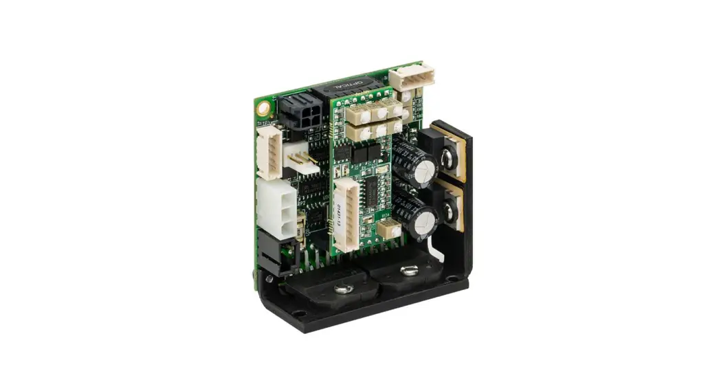
Class 1 Servo Amplifier for QS Series Galvo
Scanners
User Guide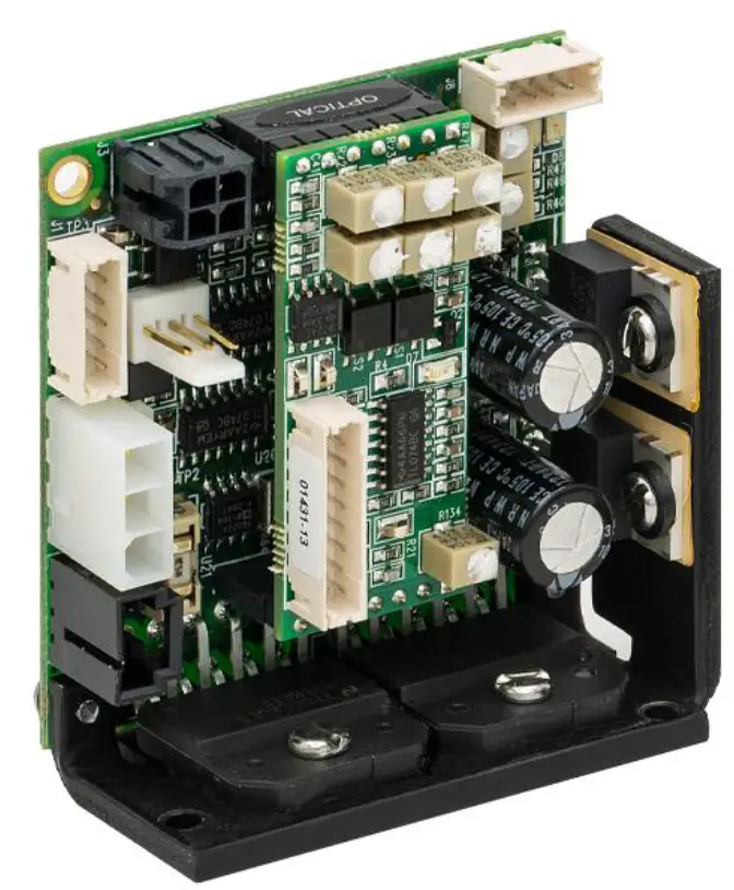
Chapter 1 Warning Symbol Definitions
Below is a list of warning symbols you may encounter in this manual or on your device
| Symbol | Description |
| Direct Current | |
| Alternating Current | |
 | Both Direct and Alternating Current |
 | Earth Ground Terminal |
 | Protective Conductor Terminal |
 | Frame or Chassis Terminal |
| Equipotential | |
| On (Supply) | |
| Off (Supply) | |
| In Position of a Bi-Stable Push Control | |
 | Out Position of a Bi-Stable Push Control |
| Caution: Risk of Electric Shock | |
 | Caution: Hot Surface |
 | Caution: Risk of Danger |
 | Warning: Laser Radiation |
 | Caution: Spinning Blades May Cause Harm |
![]() CAUTION
CAUTION![]()
Caution is given when there is a possibility of damage to the product
2.2. General Warnings
To maintain the necessary safety during the usage of Thorlabs scanners please take the following actions:
- Avoid any mechanical tension on the connection cables.
- Protect the equipment from humidity, dust, and aggressive steam to avoid damage.
- When unpacking the servo driver board(s), caution should be used to protect against static electricity, electromagnetic fields, and electrical discharges. Failure to use proper static protection may cause damage to the servo driver boards and void the manufacturer’s warranty. Damage to the electronic circuits caused by electrical discharge may not be immediately apparent – but may result in malfunction at some later time thus affecting the reliability of the product.
- Galvanometers packaged with servo drivers are factory tuned as a set. Each galvanometer is match-tuned to the servo driver, it is shipped with; these MUST stay together as a set. Servo driver boards have a copy of their mating scanner serial number on the bottom of them.
- Every servo driver is tuned to accept an input voltage range of ±5 V. Using input command voltages over the factory setting may cause the mirrors to collide. Thorlabs will not be responsible for mirror damage as a result of command input voltages that exceed the factory setting.
- Be sure that you connect the proper power supply and ground to your servo driver before operation. The power supply should have sufficient voltage and current for your application. Noisy power supplies can result in poor scanner performance. Supplies are required to have <100 mV of ripple at full load.
- For proper operation of two servo drives, be sure to attach both servo grounds together as shown in Section 4.1. Failure to do so could result in poor performance.
- If using a single-ended command signal, Pin 1 is the positive (+) command input, Pin 2 is the ground, and Pin 3 is the negative (-) command input. Be sure to attach the ground pin and the negative (-) command signal together for proper operation.
- All equipment is carefully tested and inspected before packaging. Please report any damage to your shipping company immediately.
- Servo drivers must be properly attached to a heat sink. Refer to Chapter 9: Heat Sink Requirements for proper heat sinking instructions. Failure to heat sink the servo driver could result in overheating of components, which could damage the driver and void the manufacturer’s warranty.
Chapter 3 Introduction
The QS15, QS20, QS30, and QS45 series galvanometers are shipped with a high-performance, single channel, class 1, Position, Integral, and Differential (PID) servo amplifier. It is designed to control a wide range of galvanometers and loads under a variety of command input conditions. Internal voltages are generated by precision references and regulators operating from standard ±15 V dual-output power supplies.
For your convenience, a set of mating connectors and pins for the Power, Command Input, and Diagnostic Output connectors ship with every driver board.
Diagnostic signals are readily available for monitoring:
- Motor Velocity
- Motor Position
- Position Error
- Coil Current
- AGC Voltage
- Ready Status
The following safety circuits are also included:
- Power Failure Condition
- AGC Fail / Open Loop
- Servo Ready
This manual contains all the information necessary to install and operate the servo driver along with a precision optical scanner. Servo drivers are factory tuned with a matched galvanometer and mirror. Adjustments made to the servo driver by anyone other than Thorlabs personnel will void the warranty. If it becomes necessary to return a servo driver board to the factory, the matching galvanometer and mirror should be returned along with it. Any unauthorized attempt to retune the servo by an untrained individual could result in serious damage to the scanner, mirror, and electronics![]() CAUTION
CAUTION ![]()
Each servo driver is factory tuned and matched with a galvanometer and mirror load. Unauthorized attempts to tune the servo driver in the field may result in damage to the servo, galvanometer, or mirror. The manufacturer will not cover damage as a result of unauthorized attempts to tune the servo drive. The customer may be assessed an additional fee if the servo driver and galvanometer have to be factory tuned as a result of unauthorized tuning in the field.
Chapter 4 Quick Connect Guide
Before connecting the servo drive(s), please read the General Warnings in Chapter 2.
- Adjust your dual voltage supply within the proper range of ±15 V to ±24 V before connecting the power cables.
- After adjustment, turn off the power supply before making any connections to the servo drive(s).
- The servo drive(s) should be properly mounted to a sufficient heat sink.
- For QS15 and QS20 Series Galvo Systems:
o Connect the galvanometer cable (9 pins) to the servo drive board (J1 & J6). Repeat if there is more than one galvanometer. - For QS30 and QS45 Series Galvo Systems:
o, Connect the Position Detector Cable from the Galvanometer Position Detector Connector (white, 5 Pin) to the Servo Driver Board (J1). Repeat if there is more than one Galvanometer.
o, Connect the Scanner Drive Coil Cable from the Galvanometer Drive Coil Connector (black, 3 Pin) to the Servo Driver Board (J6). Repeat if there is more than one Galvanometer. - Connect the Power Cable(s) from the Power Supply to the Servo Driver Board(s) (J7).
- Connect the Command Input Cable(s) from the function generator or host system to the servo drive board(s) (J3). If using a single-ended signal, be sure to attach the (-) negative and ground pins together at the servo drive command connector. If using a signal from a differential source, Pin 1 is the positive (+) command input, Pin 2 is the ground (-) command, and Pin 3 is the negative (-) command input.
| Power Connector – J7 (See Main Board Drawing) | |
| Pin No. | Function |
| 1 | + V Supply (+15 to +24 V) |
| 2 | Ground |
| 3 | – V Supply (-15 to -24 V) |
| Input Command Connector – J3 (See Main Board Drawing) | |
| Pin No. | Function |
| 1 | + Command |
| 2 | Ground |
| 3 | – Command |
| 4 | Offset Adjust |
| Diagnostic Output Connector – J12 (See Personality Board Drawing) | |
| Pin No. | Function |
| 1 | Galvo Position Output |
| 2 | Galvo Error Output |
| 3 | AGC Monitor |
| 4 | Velocity Output |
| 5 | Ground |
| 6 | Slew Rate Output |
| 7 | Current Monitor |
| 8 | No Connect |
| Servo Enable Connector – J8 (See Main Board Drawing) | |
| Pin No. | Function |
| 1 | Servo Ready High |
| 2 | Servo Ready Low |
| 3 | Servo Enable |
| 4 | Ground |
4.1. Ground Connections
![]() IMPORTANT!
IMPORTANT! ![]()
Proper grounding is required for good performance.
For proper performance in configurations with more than one galvo and servo driver, all servo drives should have their grounds tied together as shown below. This will reduce cross-talk between servo drives. Cross talk is a phenomenon that occurs when one servo drive demands a large amount of instantaneous current, causing the other driver to have a ground imbalance. The result is the unintentional movement of the other galvanometer. Please follow the instructions below to eliminate this issue.
- Attach a heavy gauge wire between the servo drives.

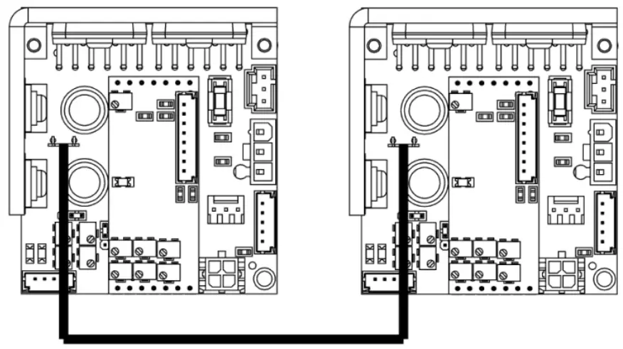
Figure 1 Grounds Connected using the J2 Quick-Fit Terminal and 50-0150 Cable (Included with 2Axis Galvo Systems)
Chapter 5 Specifications
| Servo Amplifier Specifications | |
| Inputs | |
| Command Input Range | ±5 V |
| Position Input Scale Factor | 0.22 V/° Optical |
| Command Input Impedance | 20 kΩ ± 1% (Differential) 10 kΩ ± 1% (Single Ended) |
| Position Offset Range | ±0.25 V |
| Diagnostic Outputs | |
| Servo Ready | 12 V |
| Position | 0.22 V/° Optical |
| Position Error | 0.22 V/° Optical |
| Velocity | Analog (Reference Only) |
| AGC Voltage | Analog (DC) |
| Coil Current | 1 V/A |
| Analog Output Impedance | 1 kΩ ± 1% (For All Outputs) |
| Power Supply (Not Included) | |
| Input Voltage | ±15 to ±24 VDC |
| Ripple | <100 mV Ripple |
| Noise | <0.5% DC to 30 MHz |
| Maximum Drive Current Limit | Peak: 10 Amperes per Leg RMS: 4.0 Amperes per Leg (Power Supply, Load, & Heat Sink Dependent) |
| Quiescent Current | 220 mA per Leg (Servo Enabled, Galvo Resting) |
| Gain Drift | Up to 20 ppm/°C |
| Offset Drift | Up to 30 µrad/°C |
| Environmental | |
| Operating Temperature | 0 to 45 °C (With Appropriate Cooling) |
| Storage Temperature | -10 to 60 °C |
| Dimensions | 2.38″ x 2.13″ x 1.06″ (60.5 mm x 54.1 mm x 27.0 mm) |
| Mass (Weight) | 74 g (2.6 oz) |
Chapter 6 Outline Drawings
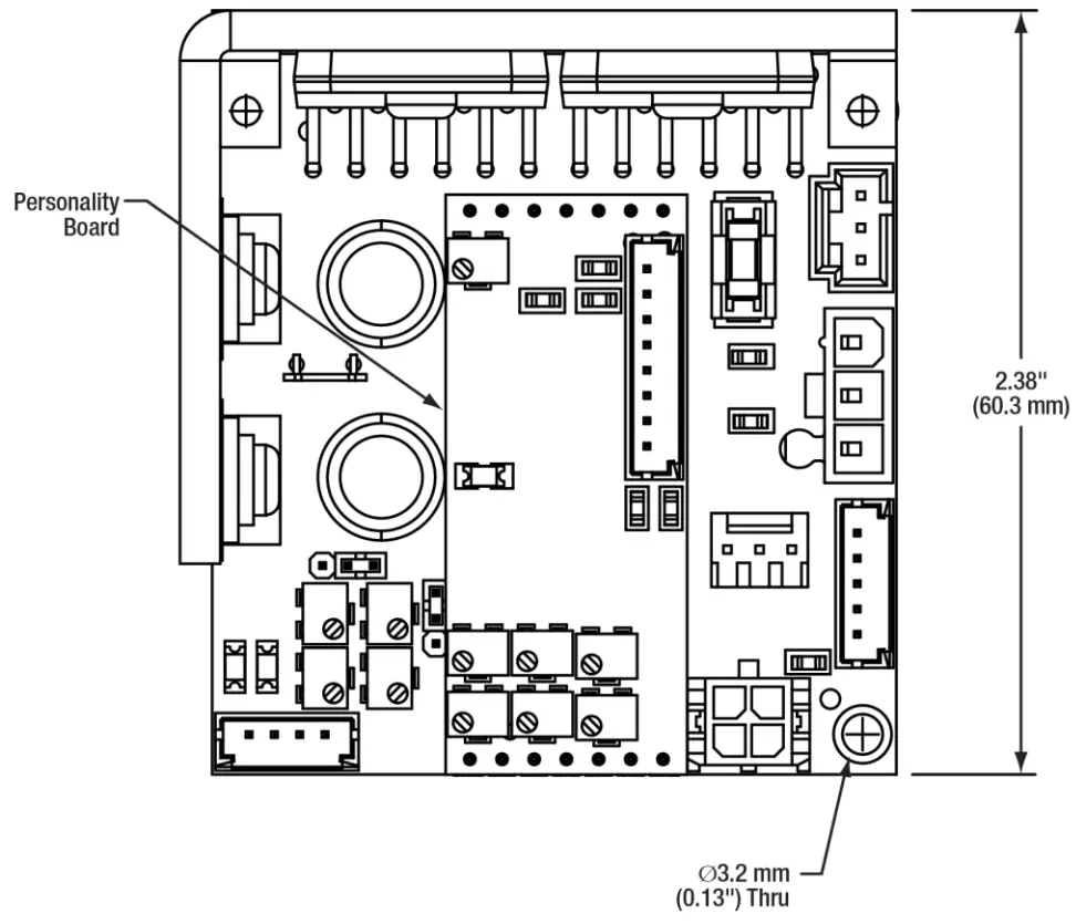 | 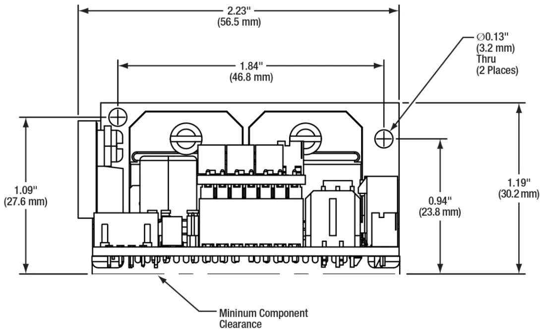 |
Figure 2 Mechanical Outline
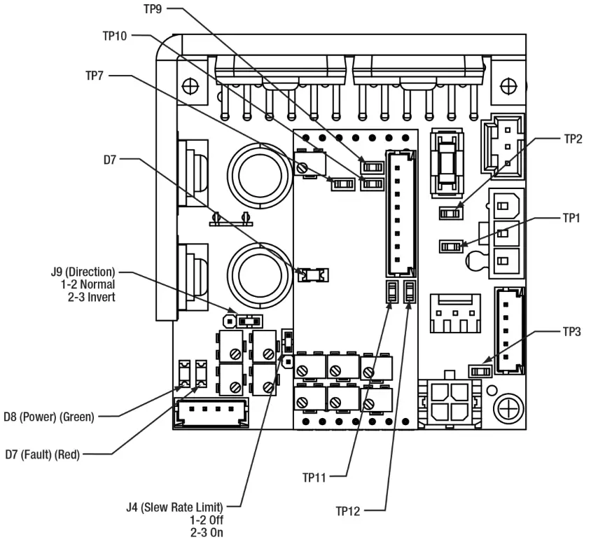
Figure 3 Jumpers, Test Points, and LEDs
| Test Points | |
| TP1 | Raw Position |
| TP2 | VIEW |
| TP3 | Filtered Command |
| TP7 | Ground |
| TP9 | PID Out |
| TP10 | Notch 1 Out |
| TP11 | Low Pass Out |
| TP12 | Offset |
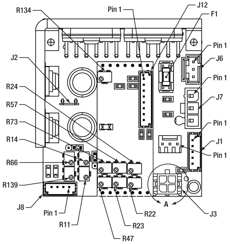
| Jumpers | Potentiometers | |||
| F1 | 5 A Fuse | R11 | PD Gain |
| J1 | Galvo PD | R14 | Slew Rate Limiter |
| J2 | Ground Lug | R22 | Position Proportional |
| J3 | Command | R23 | Damping |
| J4 | Slew Rate | R24 | Error Proportional |
| J6 | Galvo Coil | R47 | Integrator |
| J7 | Power | R57 | High-Frequency Bandwidth |
| J8 | Main Diagnostic | R66 | Command Attenuator |
| J9 | Direction Jumper | R73 | High-Frequency Damping |
| J12 | Personality Diagnostic | R134 | Notch 1 Frequency |
| R139 | Offset | ||
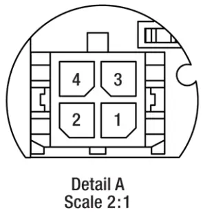
Figure 4 Connectors and Potentiometers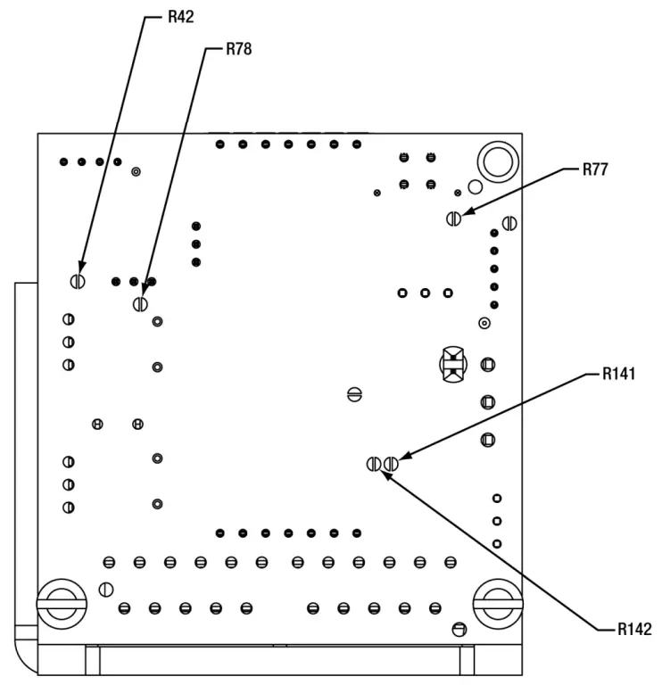
| Pins | ||
| Jumper Pos. | Open | Short |
| R42 | – | 5 V Command |
| R77 | Differential Command | Single-Ended Command |
| R78 | External Enable | Servo Enable |
| R141 | – | QS30 |
| R142 | QS30 and QS45 | – |
Chapter 7 Connectors
For your convenience, a set of mating connectors and pins for the Power, Command Input, and Diagnostic Output connectors ship with every driver board.
7.1. Power Connector (Main Board – J7)
The mating connector is a Molex 39-01-4031 or 39-01-4030 connector with (3) Molex 39-00-0183 or 39-00-0184 pins. The pins should be used with AWG 22-28 wire.
The power connector (J7) is used to deliver the appropriate voltage to the servo driver board. Pin 1 is the positive supply voltage. Pin 2 is the ground. Pin 3 is the negative supply voltage.
A power supply with sufficient output current should be used. The output current required depends on the supply voltage, galvanometer model, mirror load, command waveform, and duty cycle. Lower supply voltages, larger galvanometers, larger mirrors, and more demanding waveforms and duty cycles will require more current. It is a good practice to set up your application with a laboratory power supply and measure the required current during the most demanding application your system can run. Then select a power supply appropriate for your application.
The servo driver has two generous output capacitors, which supply instantaneous peak current to the output drive amplifiers and lower the peak output requirements of your system power supply.
| Power Connector – J7 (See Servo Driver Drawing) | |
| Pin No. | Function |
| 1 | + V Supply (+15 V) |
| 2 | Ground |
| 3 | – V Supply (-15 V) |
7.2. Command Input Connector (Main Board – J3)
The mating connector is a Molex 43025-0400 connector with (4) Molex 43030-0003 or 43030-0009 pins. The pins should be used with AWG 20–24 wire.
The analog command input comes in on the connector (J3). For differential inputs, Pin 1 is the positive (+) command input, Pin 2 is ground, and Pin 3 is the negative (-) command input. Switching the input polarity of Pins 1 and 3 will reverse the rotation of the galvanometer shaft.
The input can be configured for single-ended or differential operation.
IMPORTANT NOTE: For single-ended operation Pin 1 is the positive (+) command input, Pin 2 is the ground, and Pin 3 is also tied to the ground. This is done by applying a solder bridge to R77.
| Input Command Connector – J3 (See Servo Driver Drawing) | |
| Pin No. | Function |
| 1 | + Command |
| 2 | Ground |
| 3 | – Command |
| 4 | Offset Adjust |
An external offset adjust is provided on pin 4 of the input command connector. This option is generally not used and this pin may be left floating. The offset is adjusted internally to zero at the factory.
For certain 3-axis applications, it may be desirable to externally calibrate the third axis (focus) by introducing an analog DC offset to pin 4. Up to ±10 volts may be applied; however, the combination of command and offset can not exceed the normal range of motion.
7.3. Diagnostic Output Connector (Personality Board – J12)
The mating connector is a Molex 51090-0800 connector with (8) Molex 50212-8000 or 50212-8100 pins. The pins should be used with AWG 24–30 wire.
The diagnostic output connector (J12) provides several output signals that are used to monitor various functions of the servo and galvanometer. See the output signal specifications in Chapter 5 for more details.
| Diagnostic Output and Servo Enable Connector – J12 (Optional) | |
| Pin No. | Function |
| 1 | Galvo Position Output |
| 2 | Galvo Error Output |
| 3 | AGC Monitor |
| 4 | Velocity Output |
| 5 | Ground |
| 6 | Slew Rate Output |
| 7 | Current Monitor |
| 8 | Not Connected |
7.3.1. Position Output
The position output signal (J12, Pin 1) provides a scaled instantaneous position output from the galvanometer that is buffered through an amplifier. The signal may be used to trigger an event when a position is reached or used when tuning the servo driver.
7.3.2. Position Error Output
The position error output signal (J12, Pin 2) is the difference between the command input signal and the position signal. It can be used to signal the arrival at a command location or as a tracking offset (continuous position error).
7.3.3. AGC Monitor
The AGC signal (J12, Pin 3) is a voltage that drives the galvanometer position detector’s oscillator. If found to be excessive, this could suggest position detector problems.
7.3.4. Velocity Output
The Velocity output signal (J12, Pin 4) is the instantaneous angular velocity of the galvanometer rotor. It is used for tuning the servo drive and to monitor variations in velocity, which may be important in some applications like raster scanning.
7.3.5. Slew Rate Output
The Slew-Rate output signal (J12, Pin 6) is the command signal being passed to the control loop if the Slew-Rate circuit has been enabled.
7.3.6. Current Monitor
The Current signal (J12, Pin 7) is the current that is being sent to the galvanometer coil. The signal is represented as 1V/Amp of current in the coil.
7.4. Servo Enable Connector (Main Board – J8)
The mating connector is a Molex 51090-0400 connector with (8) Molex 50212-8000 or 50212-8100 pins. The pins should be used with AWG 24–30 wire.
| Servo Enable Connector – J8 (See Servo Driver Drawing) | |
| Pin | Function |
| 1 | Servo Ready High |
| 2 | Servo Ready Low |
| 3 | Servo Enable |
| 4 | Ground |
The servo enables input (J8, Pins 3, and 4) and allows the host control system to remotely enable or disable the servo driver. When Pin 3 is pulled low by connecting it to the ground available at Pin 4, the servo is enabled. When Pin 3 is floating, the servo is disabled and will not move in response to input commands.
NOTE: The servo board is shipped with a solder bridge (R78), which disables the remote servo enable. The solder bridge (R78) must be removed for the remote servo to enable the operation to function.
![]() CAUTION
CAUTION ![]()
This input should not be used as an interlock. The use of a shutter or other safety measures should be used for protection from laser radiation.
7.5. Galvanometer Cables, Connections, and Jumpers
Each QS30 and QS45 series galvanometer requires two cables for connection to the servo driver board. One cable provides current to the drive coil (stator). The other cable provides power to the position detector circuit and communicates the return position signal to the servo. The two cables are shielded and separated to prevent coupling of the drive signal into the position feedback signal.
QS15 and QS20 series galvanometers have a single cable connecting the servo driver to the galvanometer.
7.5.1. Galvanometer Coil Connector (Main Board – J6)
The mating connector is a Molex 50-57-9403 connector with (3) Molex 16-02-0082 or 16-02-0097 pins. The pins should be used with AWG 24–30 wire.
The galvanometer drive coil connector (J6) receives the galvanometer drive cable. The drive cable connects between (J6) on the servo driver board and the drive coil connector on the galvanometer. There are two conductors and a shield that terminates to a floating terminal inside the galvanometer.
| Galvanometer Coil Connector – J6 (see Servo Driver Drawing) | |
| Pin | Function |
| 1 | Coil + |
| 2 | Coil – |
| 3 | Shield |
7.5.2. Galvanometer Position Signal Connector (Main Board – J1)
The mating connector is a Molex 51090-0500 connector with (5) Molex 50212-8000 or 50212-8100 pins. The pins should be used with AWG 24–30 wire.
The galvanometer position signal connector (J1) receives the galvanometer position cable. The position cable connects between (J1) on the servo drive board and the position signal connector on the galvanometer. There are four conductors and a shield that drains to the servo only; it is not connected to a galvanometer. The other conductors carry the ± position signals, power, and ground.
| Galvanometer Position Signal Connector – J1 (see Servo Driver Drawing) | |
| Pin | Function |
| 1 | Position + |
| 2 | Position – |
| 3 | Ground |
| 4 | OSC Power (AGC) |
| 5 | Shield |
7.5.3. Slew Rate Limit Jumper (Main Board – J4)
The mating connector is a Samtec 2SN-BK-G shunt connector.
| Slew Rate Limiter – J4 | |
| Position | Function |
| 1-2 | OFF |
| 2-3 | ON |
7.5.4. Direction Jumper (Main Board – J9)
The mating connector is a Samtec 2SN-BK-G shunt connector.
| Direction Jumper – J9 | |
| Position | Function |
| 1-2 | Normal |
| 2-3 | Inverted |
Chapter 8 Power Requirement
| Power Requirements | |
| Input Voltage | ±15 VDC |
| Ripple | <100 mV Ripple |
| Noise | <0.5% DC to 30 MHz |
| Maximum Drive Current Limit | Peak: 10 A per Leg RMS: 4.0 A per Leg (Power Supply, Load, & Heat Sink Dependent) |
| Quiescent Current | 220 mA per Leg (Servo Enabled, Galvo Resting) |
A dual-output, linear power supply with sufficient output current should be used. The output current required depends on the supply voltage, galvanometer model, mirror load, command waveform, and duty cycle. Lower supply voltages, larger galvanometers, larger mirrors, and more demanding waveforms and duty cycles will require more current. It is a good practice to set up your application with a laboratory power supply and measure the required current during the most demanding application your system can run. Then select a power supply appropriate for your application.
Select a high-quality power supply with good clean DC outputs. Power supplies with excessive ripple or noise will cause scanning problems in your system.
The servo driver has two generous output capacitors, which supply instantaneous peak current to the output drive amplifiers and lower the peak output requirements of your system power supply.
Chapter 9 Heat Sink Requirements
![]() WARNING
WARNING![]()
The servo driver board MUST be attached to an additional heat sink before applying power. Failure to provide proper heat sinking could result in damaged components and could void the manufacturer’s warranty.
Each servo drive board has two output amplifiers and two voltage regulators, which require heat sinking. These devices are mounted to an L-shaped bracket attached to the board. This bracket does not provide sufficient heat sinking for normal operation. The servo drive heat sink must be attached with at least two screws to a larger, thermally conductive surface, such as an aluminum plate. Make sure that the surface is flat and that the two plates are in good contact with each other. Thorlabs recommends using thermal paste and selecting a heat sink surface with exposure to the outside surface of the host system.
The amount of heat that needs to be dissipated depends on several factors including the size of the galvanometer and mirror, the galvanometer stator resistance, the command waveform and duty cycle, and the ambient temperature.
It is suggested that the temperature of the servo driver heat sink near the output amplifiers not exceed 55 °C. Some trial and error may be required in each application to reach the appropriate amount of heat sinking.
Chapter 10 Protection Circuits
10.1. Servo Faults
The servo driver has a green Servo Power LED (D8) and a red Fault LED (D7) that indicates if one of the fault conditions has occurred. The Main Board Connector (J8) provides two unique signals that indicate if a fault has occurred.
| Servo Status LED’s – D7 and D8 (see Servo Driver Drawing) | ||
| LED # | Color | Status |
| D8 | Green | Power On |
| D7 | Red | Servo Fault |
- Servo Power: The ± voltage regulators are on.
- Fault: A fault condition has occurred.
10.1.1. Power Failure Condition
If the green LED is off or dim, one of the two voltage rails (+ or – supply voltage) is not present.
10.1.2. Under Voltage Condition
If the red LED is on, one or both of the voltage rails may be less than +14 or –14 volts.
10.1.3. Over Position Condition
If the red LED is on, the galvanometer rotor may be more than 6% out of position range.
10.1.4. AGC Fail / Open Loop Condition
If the red LED is on, there may be a failure in the automatic gain control loop or the servo loop is open.
10.1.5. Servo Ready Signal
When the servo drive is ready, the Servo Ready Hi output signal (Pin 1 of connector J8) goes low (0 volts) and the Servo Fault LED (Red, D7) is off. If there is a fault, the Servo Ready output will go high and the Fault LED (Red, D7) is on. The Servo Ready Lo output is an inverted version of the Servo Ready Hi output.
| J8 Pin No. | Fault | No-Fault |
| 1 (Servo Ready Hi) | 0 V | +12 V |
| 2 (Servo Ready Lo) | +12 V | 0 V |
10.2. Fuse
The servo driver has one 5 A slow blow fuse to protect against excessive coil current. The fuse manufacturer and part number are the following:
Littelfuse
Part Number: 0454005.
Replacement fuses are available from the following:
Digi-Key Electronics
Part Number: 0454005.MR-ND
Chapter 11 Regulatory
As required by the WEEE (Waste Electrical and Electronic Equipment Directive) of the European Community and the corresponding national laws, Thorlabs offers all end users in the EC the possibility to return “end of life” units without incurring disposal charges.
- This offer is valid for Thorlabs electrical and electronic equipment:
- Sold after August 13, 2005
- Marked correspondingly with the crossed out “wheelie bin” logo (see right)
- Sold to a company or institute within the EC
- Currently owned by a company or institute within the EC
- Still complete, not disassembled, and not contaminated

Wheelie Bin Logo
As the WEEE directive applies to self-contained operational electrical and electronic products, this end-of-life take-back service does not refer to other Thorlabs products, such as:
- Pure OEM products, that means assemblies to be built into a unit by the user (e. g. OEM laser driver cards)
- Components
- Mechanics and optics
- Leftover parts of units disassembled by the user (PCBs, housings, etc.).
If you wish to return a Thorlabs unit for waste recovery, please contact Thorlabs or your nearest dealer for further information.
Waste Treatment is Your Own Responsibility
If you do not return an “end of life” unit to Thorlabs, you must hand it to a company that specialized in waste recovery.
Do not dispose of the unit in a litter bin or at a public waste disposal site.
Ecological Background
It is well known that WEEE pollutes the environment by releasing toxic products during decomposition. The aim of the European RoHS directive is to reduce the content of toxic substances in electronic products in the future.
The intent of the WEEE directive is to enforce the recycling of WEEE. Controlled recycling of end-of-life products will thereby avoid negative impacts on the environment.
Chapter 12 Thorlabs Worldwide Contacts
For technical support or sales inquiries, please visit us at www.thorlabs.com/contact for our most up-to-date contact information.

| USA, Canada, and South America Thorlabs, Inc. [email protected] [email protected] | UK and Ireland Thorlabs Ltd. [email protected] [email protected] |
| Europe Thorlabs GmbH [email protected] | Scandinavia Thorlabs Sweden AB [email protected] |
| France Thorlabs SAS [email protected] | Brazil Thorlabs Vendas de Fotônicos Ltda. [email protected] |
| Japan Thorlabs Japan, Inc. [email protected] | China Thorlabs China [email protected] |

![]()


