KLUS PDS-4-PLUS Extrusion Instruction Manual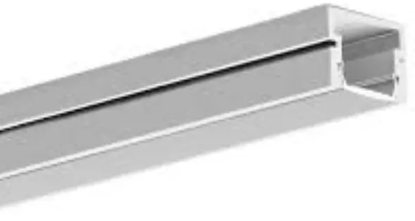
Tools
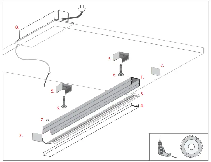
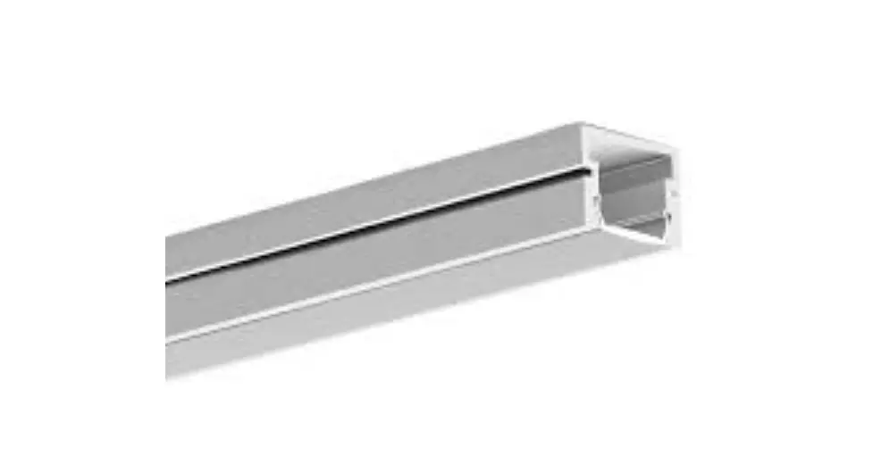
- PDS-4-PLUS extrusion (Ref. C1263)
- End cap*
- LED strip*
- Cover*
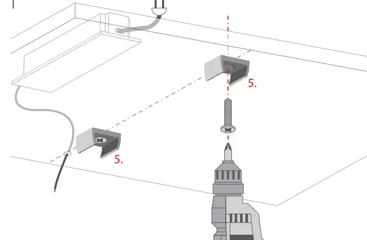
- Mounting bracket*
- Countersunk screw (6-8 mm / 0.24-0.31”)
- Gland*
- Power supply (12 V / 24 V)*
*The selection of electronics and types of accesories available on www.KlusDesign.com
NOTE! All LED strips must be connected to a 12 V or 24 V power supply.
IMPORTANT: The manual does not present all methods of montage. Other related accessories with instructions of their mounting procedures available at www.KlusDesign.com. Drawings of extrusions and accessories in this manual are simplified and only approximately represent the real shapes.
Turn off LED lights during peak day light hours in outdoor applications to avoid excessive heat buildup which will result in diminished LED life.
Mounting Instruction
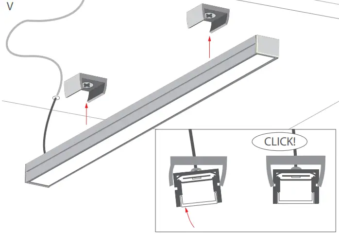
- Screw the mounting brackets (5) tothe surface

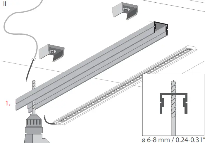
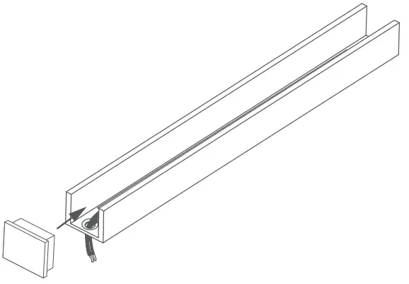
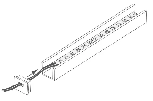
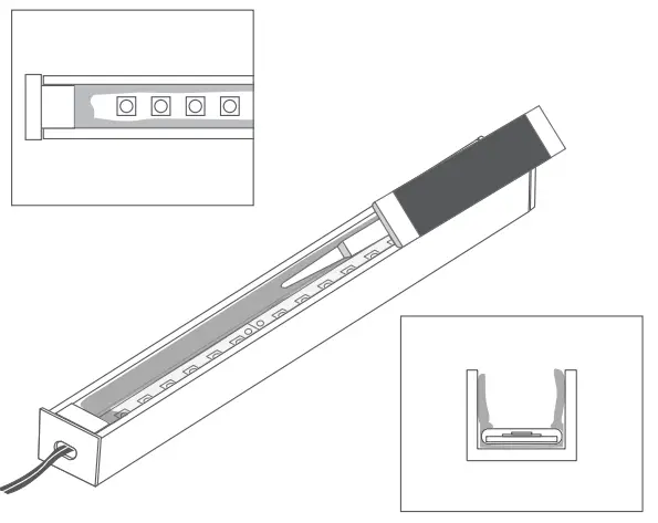
- Drill a hole for the power cord in the PDS-4-PLUS extrusion (1).

- Mount the gland (7) and run the power cord through the drilled hole.
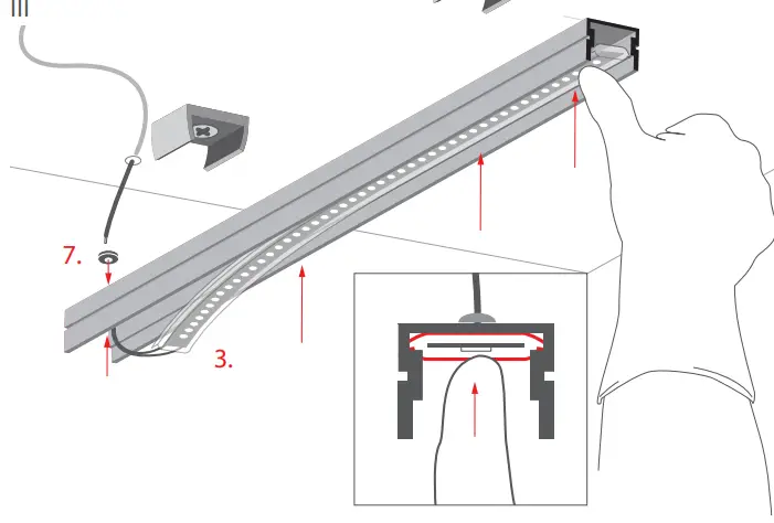
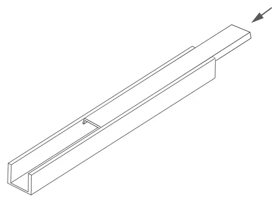
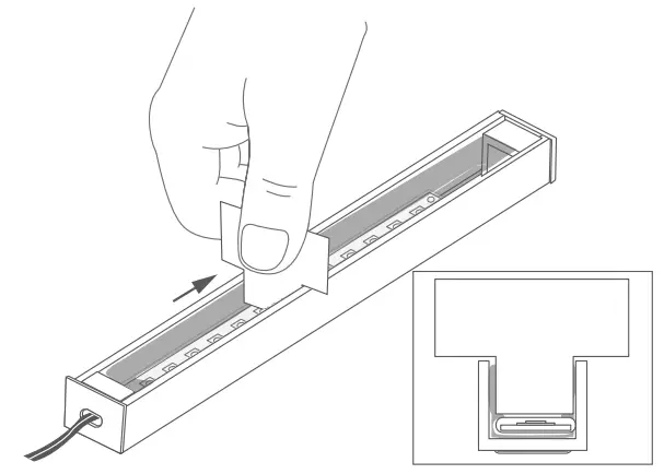
Insert the 8-KLIK sleeve (3) into the extrusion.
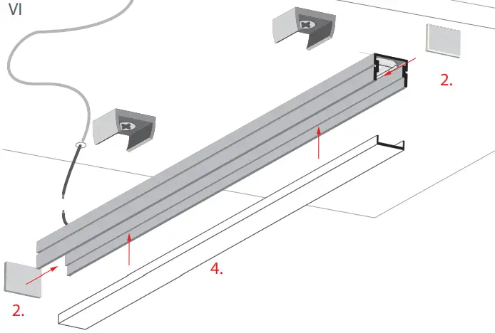
- Attach the end caps (2) and the cover.

- Connect the power and insert the lighting fixture into the mounting brackets.
LED strip must be connected to a 12 V or 24 V power supply
Cutting and drilling
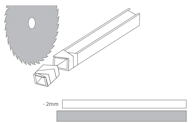
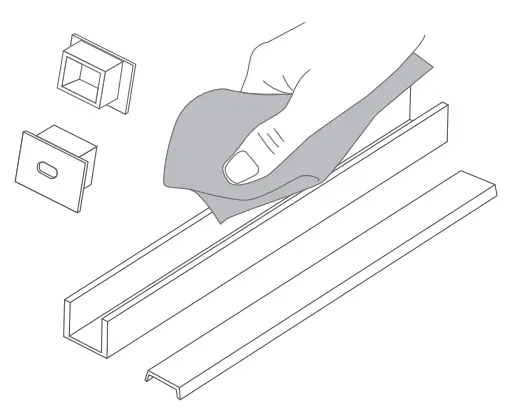
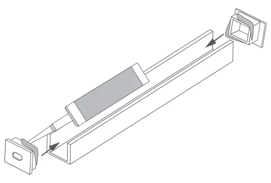
- Before cutting the extrusion with the cover, secure the cutting point with self-adhesive tape.

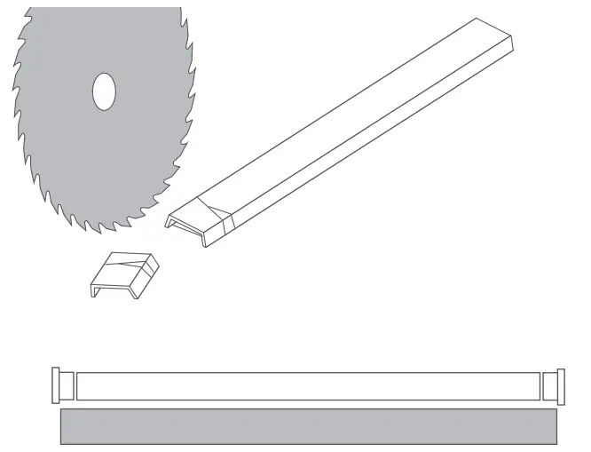
- Use a mechanical saw to cut.
NOTE! It is recommended that the cover be cut 2 mm shorter than the extrusion to account for its thermal expansion.
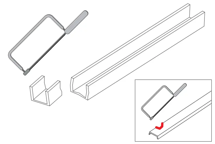
NOTE! Low precision cutting of the extrusion and cover can be done with a hand saw, however, uneven, jagged edges will remain, and the covers may break.
NOTE! For some extrusions there are dedicated end caps that require adequate shortening of the cover.
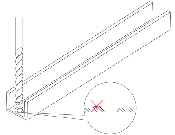
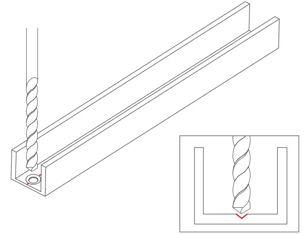
- Drill a hole in the extrusion in the selected place.
NOTE! Make sure that there are no burrs around the hole after drilling as they can damage the LED strip or cable.
NOTE! Some extrusions feature one or more special grooves that make it easier to start drilling.
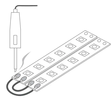
Adhering and connecting LED strips
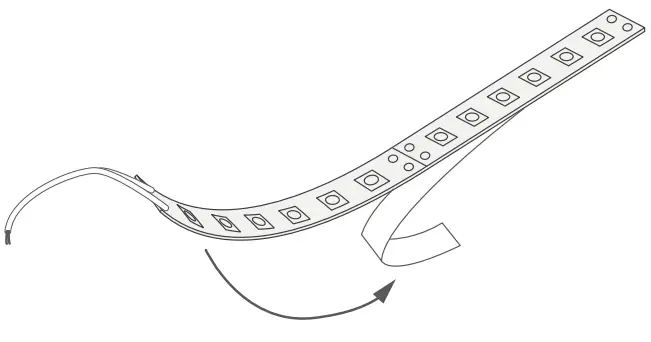
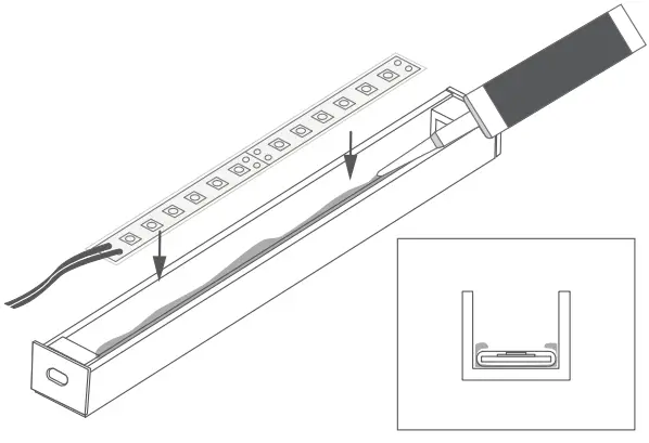
- Remove the protective layer of the LED strip.

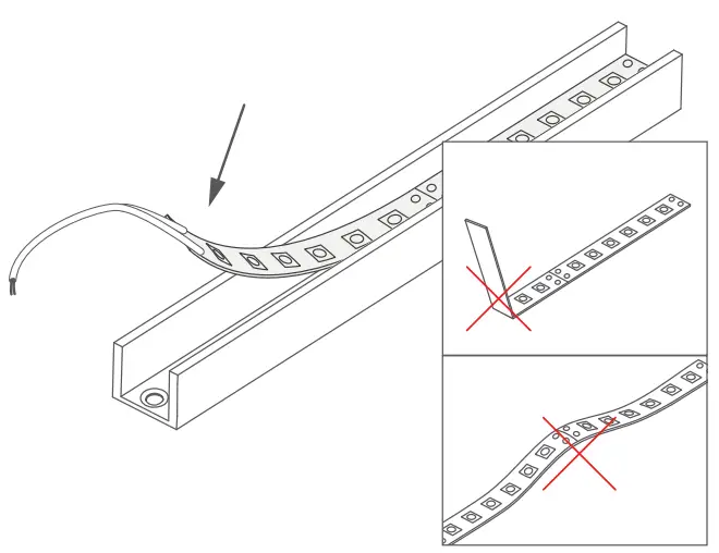
- Attach the tape in the extrusion using the adhesive provided on the LED strip.
NOTE! The tape must not be bent or peel off the surface.
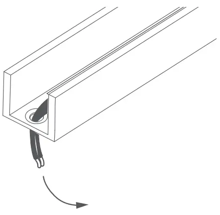
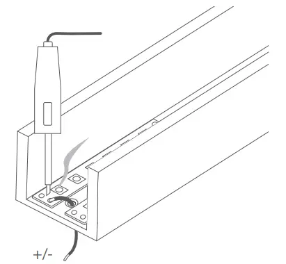
- Lead the power cable through the drilled hole.

- Connect the LED strips with wires by soldering.

OPTIONALLY: The LED strips can also be connected using a system of LED strip connectors. More information at www.klusdesign.com
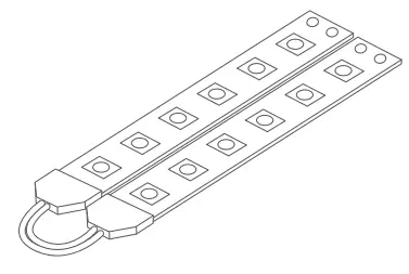
OPTIONALLY: The power cords can be led out from one pole of a given strip. This method is used to power suspended lighting fixtures.
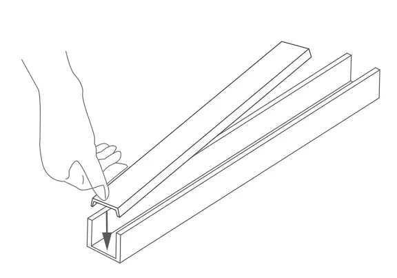
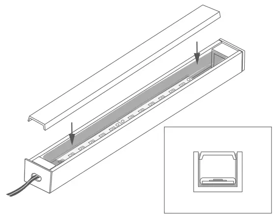
Attaching covers and end caps
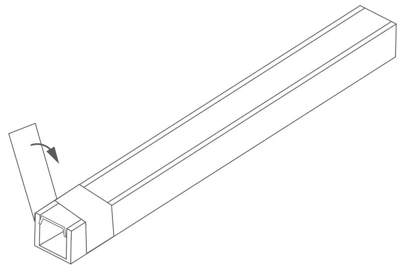
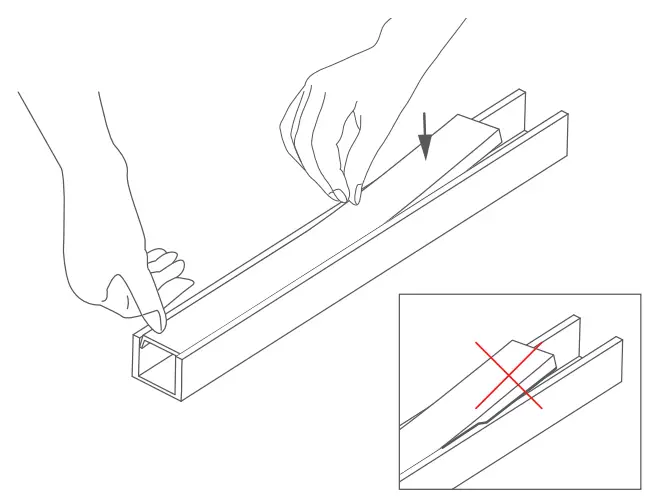
- Insert the tip of the cover into the extrusion.

- Press in the subsequent sections of the cover. Be careful not to bend or break the wings of the cover.

OPTIONALLY: Short sections, can also be inserted from the edge of the extrusion.
- Insert an end cap into the edge of the extrusion. Individual extrusions have a shape that allows easy installation of dedicated end caps.
NOTE! Some end caps require an adequately shortened cover. This should be taken into account when cutting the extrusion and the cover.
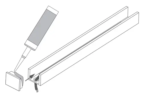
OPTIONALLY: It is recommended to attach the end caps to the extrusion with use of glue.
OPTIONALLY: Power cables can be run through the end caps in which case the extrusion does not need to be drilled through.
Sealing the profile
- Clean dust and dirt from the extrusion and accessories.

- Attach the end caps with glue.

- Apply a silicone layer to the bottom of the profile and embed the LED strip in it.

NOTE: The LED strip must have separate protection against moisture.
We recommend a silicone sleeve or heat shrink tubing if the strip in the sleeve does not fit into the extrusion. - Apply a second layer of silicone on the extrusion walls and the end caps.

- Remove the excess silicone with a rectangular tool (e.g. a piece of cardboard), taking care not to damage the tape. The silicone layer must be even and must not obscure the LEDs.

- Insert the cover.

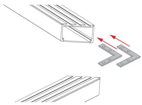
Connecting profiles using ZM connectors
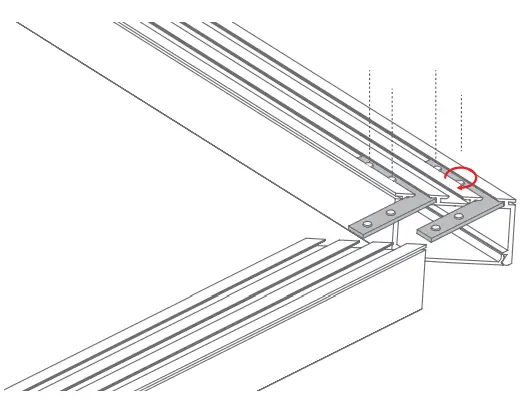
- Slide the connectors into the small locks of the extrusion.

- Tighten the two pressure screws in each connector with an Allen wrench

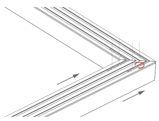
- Slide the other half of the extrusion onto the connectors and tighten the pressure screws with an Allen wrench.