LINEAR TECHNOLOGY DC2369A Low Power Wireless Current Sense
INTRODUCTION
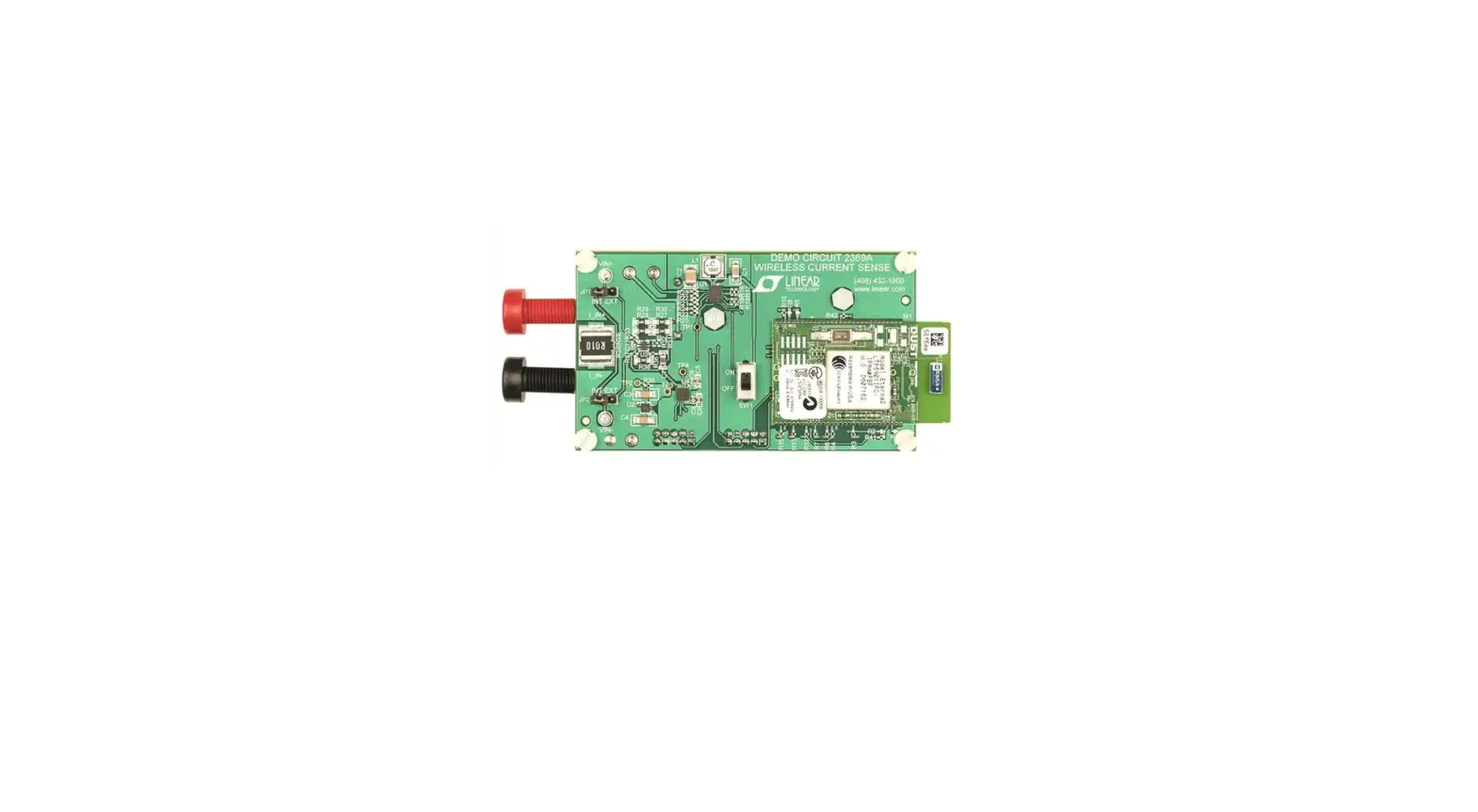
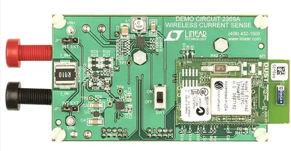
The DC2369A demo circuit is a reference design that implements a wireless current sense solution using Linear Technology’s low-power integrated circuits. The only external connection needed is current to be measured, allowing this circuit to be inserted at any voltage level or isolation level. The design combines components for current measure-ment, power management, and wireless mesh networking. A micro-power zero-drift op amp (LTC®2063) amplifies the voltage across a sense resistor. A 16-bit SAR ADC and precision reference (AD7988 and LT®6656) digitize the reading. A SmartMesh IP™ wireless radio module (LTP5901-IPM) runs the application, provides wire-less mesh connectivity, and communicates with a central network manager. A switching power supply (LTC3335) counts the cumulative charge drawn from the included battery while also regulating the output voltage for the rest of the application. Table 1 shows the featured components used along with their function.
Design files for this circuit board are available at http://www.linear.com/demo/DC2369A.
L, LT, LTC, LTM, Linear Technology, SmartMesh, and the Linear logo are registered trademarks and SmartMesh IP is a trademark of Analog Devices, Inc. All other trademarks are the property of their respective owners.
Table 1
| LTC PART NUMBER | FUNCTION | BENEFITS |
| LTC2063 | 2µA Zero-Drift Op Amp | Measures Small Voltage Drop Across Sense Resistor to Measure Current |
| AD7988-1 | 100ksps Ultra Low Power 16-Bit SAR ADC | Digitizes Measurement from Op Amp While Consuming <1µA at Low Sample Rate |
| LT6656-3 | 1µA Precision Voltage Reference | <10ppm/°C Reference for Stable ADC Measurement. Provides Low Noise Supply for Op Amp |
| LTP5901-IPM | SmartMesh IP Mote Module | Automatically Forms Low Power, Reliable Wireless Network. Built-In Microprocessor Manages ADC and Power Supplies |
| LTC3335 | Nanopower Buck-Boost DC/DC with Integrated Coulomb Counter | Measures Total Charge Drawn from Battery. Regulates Output Supply for the Rest of Application |
DC2369A CONNECTIONS AND JUMPERS
- Set the slide switch SW1 to ON to power the circuit. DC2369A is powered by its included two AAA batteries and therefore does not need an external power supply. The slide switch asserts the enable pin of the LTC3335. You may verify the correct operation of the power supplies by measuring (on the back of the circuit board) that VDD – GND = 3.3V and VREF – GND = 3.0V.
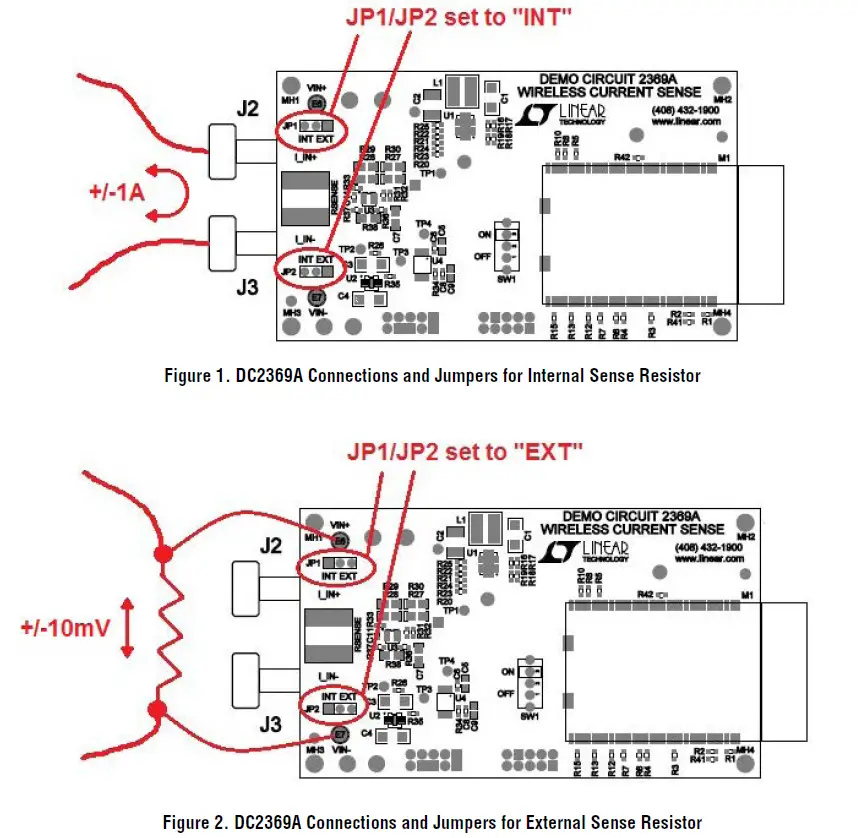
- The only external connection needed to the DC2369A is for the current to be measured. The DC2369A circuitry does not draw its power from this current – it only uses it to develop a small voltage drop across the included 10mΩ sense resistor. The DC2369A is designed to measure up to ±1A full-scale current, developing a ±10mV voltage drop across the sense resistor. Connect the current to be measured using the banana connectors (J2 and J3). Set jumpers JP1 and JP2 to the INT position (to use the internal sense resistor). See Figure 1.
- Alternatively, DC2369A can be used to measure the voltage across an external sense resistor. In this case, set jumpers JP1 and JP2 to EXT, and connect the voltage
to be measured to the turrets labeled VIN+ and VIN–. The preconfigured DC2369A firmware and software will still assume a ±10mV full-scale input voltage and report that as a ±1A full-scale current. See Figure 2.
INSTALL THE DC2369A GUI
For demonstration purposes, a small sample Python based graphical user interface (GUI) application was designed to subscribe to all incoming DC2369A device messages and display the data.
For more information on programming to the management software application programming interface (API), refer to the SmartMesh IP Embedded Manager API Guide.
- Install FTDI USB-to-Serial Drivers
In order for your computer to communicate with the Manager, you may first need to install a driver from FTDI. You should be able to simply follow the instructions within the driver installer, but detailed instructions are also available in the Setup section of the SmartMesh IP Tools Guide. - Download GUI
The DC2369A GUI is found with this demo circuit’s documentation on www.linear.com/demo. Download and extract the zip file to a convenient location on your computer.
FORM THE WIRELESS NETWORK
This document assumes some basic familiarity with Smart-Mesh IP wireless networking. Refer to the SmartMesh IP Easy Start Guide if needed.
- Use any SmartMesh IP manager such as the DC2274A-A SmartMesh IP USB Network Manager. Be aware of the manager’s network ID.
- Turn on power to at least three SmartMesh IP motes, operating on the same network ID as the manager. DC2369A will co-exist in a network with any other SmartMesh IP motes (of the same network ID), such as motes from the SmartMesh IP Starter Kit DC9021B.
- All DC2369A motes are shipped factory-programmed to the default network ID of 1229. This is the same network ID programmed by default into the standard SmartMesh IP evaluation kits. If it is needed to change the network ID of this mote to match the one used in your network, the DC2369A API or CLI can be accessed through the 10-pin connector labeled J1 PROG on the back of the board.
- Connect the manager to a computer USB port. The network should now form. Proper operation of the network can be monitored by accessing the manager CLI or API in the usual manner.
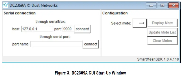
- Open the DC2369A GUI. You will see a window similar to that shown in Figure 3.

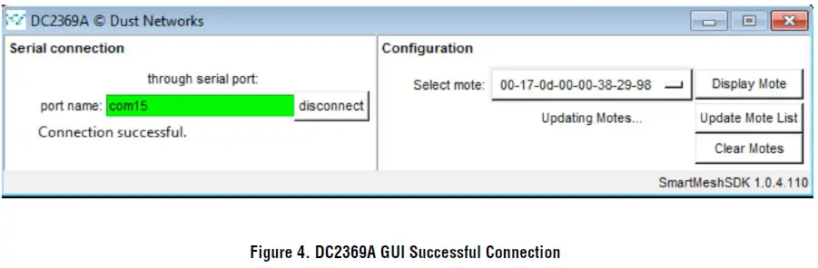
- In the port name field, enter the COM port that corresponds to the Manager API. This is typically the last of the four COM ports added. Then click the connect button. The GUI window will change as shown in Figure 4 if the connection is successful. If you don’t know what the Manager API COM port is, refer to the SmartMesh IP Tools Guide for instructions.
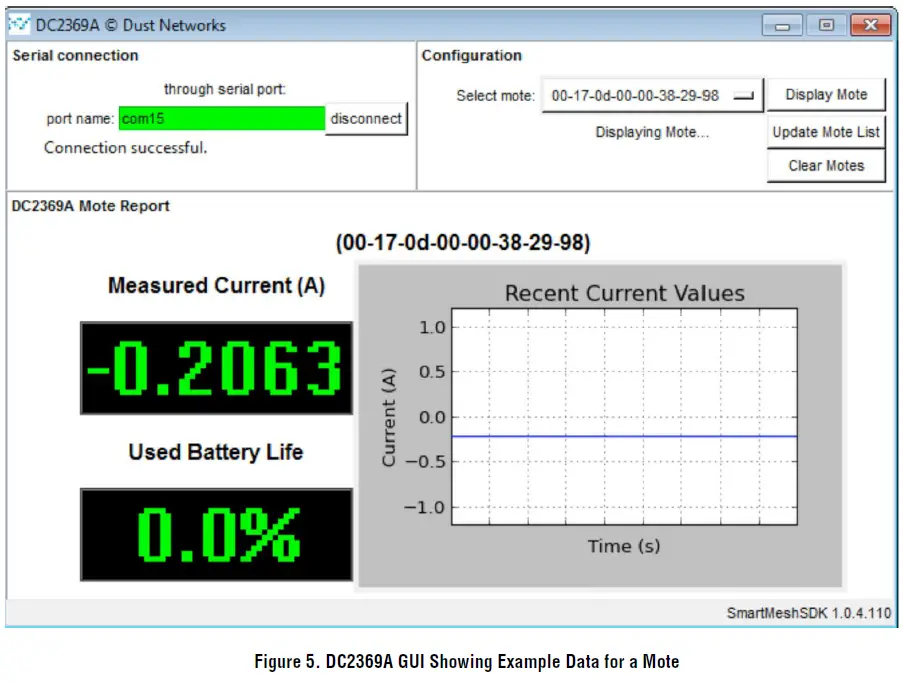
- To select a mote for display, see the Select mote: pull-down menu in the Configuration section, and select from the list of connected motes. The pull-down list will be populated with the MAC address of all DC2369A motes that are found on the network. The last few digits of these MAC addresses can also be found on a label on your DC2369A motes. Click on Display Mote. The GUI window will change similar to Figure 5.
- Measured Current (A) shows the current measured between the DC2369A input connectors. Used battery life shows an estimation of the percentage of the AAA batteries that have been used since the last reset, based on the coulomb counter reading of the mote’s LTC3335 power supply. This will likely start at 0.0% when the mote first powers up, and will only change after many hours of operation.


SOURCE CODE
- DC2369A has been preprogrammed with custom firmware that runs on the internal microprocessor of the LTP5901-IPM. This firmware has been created in the SmartMesh IP On-Chip SDK (OCSDK) and can be accessed on GitHub.
- The DC2369A GUI has been created in Python, and built on the SmartMesh® SDK. The source code can be accessed on GitHub.
PARTS LIST
| ITEM | QTY | REFERENCE | PART DESCRIPTION | MANUFACTURER/PART NUMBER |
Required Circuit Components
| 1 | 1 | BTH1 | BATTERY HOLDER, 2CELL AAA, PC MNT | KEYSTONE, 2468K-ND |
| 2 | 1 | C1 | CAP, CHIP, X5R, 22µF, 20%, 6.3V, 1206 | SAMSUNG, CL31A226MQHNNNE |
| 3 | 1 | C2 | CAP, CHIP, X5R, 150µF, 20%, 6.3V, 1210 | SAMSUNG, CL32A157MQVNNNE |
| 4 | 2 | C3, C4 | CAP, CHIP, X7R, 22μF, ±10%, 10V, 1206 | MURATA, GRM31CR71A226KE15L |
| 5 | 2 | C5, C9 | CAP, CHIP, X7R, 1μF, ±10%, 10V, 0603 | TDK, C1608X7R1A105K080AC |
| 6 | 3 | C6, C8, C11 | CAP, CHIP, X7R, 0.1μF, ±10%, 10V, 0402 | TDK, C1005X7R1A104K050BB |
| 7 | 1 | C7 | CAP, CHIP, X7R, 10μF, ±10%, 10V, 0805 | TDK, C2012X7R1A106K125AC |
| 8 | 6 | E1, E2, E3, E4, E6, E7 | TURRET, 0.061 DIA | MILL-MAX, 2308-2-00-80-00-00-07-0 |
| 9 | 2 | J1, J4 | 5 x 2 HEADER 2MM | MOLEX, 87831-1020 |
| 10 | 1 | J2 | BANANA JACK, RED | CONN SOLUTIONS, 108-0902-001 |
| 11 | 1 | J3 | BANANA JACK, BLACK | CONN SOLUTIONS, 108-0903-001 |
| 12 | 2 | JP1, JP2 | HEADER, 2MM, 1X3POS | SAMTEC, TMM-103-02-L-S |
| 13 | 2 | JP1, JP2 | SHUNT, 2MM | SAMTEC, 2SN-KB-G |
| 14 | 1 | L1 | IND, SMT, 100μH, 1.40, 350mA, 4mm x 4mm x 1.8mm | COILCRAFT, LPS4018-104MLB |
| 15 | 1 | M1 | SmartMesh IP MOTE MODULE | LINEAR TECH, LTP5901IPC-IPMA#PBF |
| 16 | 4 | R1, R2, R5, R8 | RES, CHIP, 100kΩ, 1% 1/10W 0402 | VISHAY MCS04020C1003FE000 |
| 17 | 8 | R3, R4, R6, R17, R20, R22, R24, R26 | RES, CHIP, 0.0Ω JUMPER, 1/16W | VISHAY CRCW040220000Z0ED |
| 18 | 5 | R7, R10, R12, R13, R15 | RES, CHIP, 34Ω, 1% 1/10W 0402 | PANASONIC, ERJ-2RKF34R0X |
| 19 | 0 | R16, R21, R23, R25, R31, R32, R41 | OPTIONAL, DO NOT POPULATE | |
| 20 | 2 | R18, R19 | RES, CHIP, 4.99kΩ, 1% 1/10W 0402 | PANASONIC, ERJ-2RKF4991X |
| 21 | 5 | R27, R28, R29, R30, R38 | RES, CHIP, 2MΩ, ±0.1%, 1/10W, 0805 | TE CONNECTIVITY, CPF0805B2MOE1 |
| 22 | 2 | R33, R37 | RES, CHIP, 14kΩ, ±0.1%, 1/16W, 0402 | TE CONNECTIVITY, CPF0402B14KE1 |
| 23 | 1 | R36 | RES, CHIP, 10kΩ, 1/10W, 0402 | PANASONIC ERJ-2RKF1002X |
| 24 | 1 | R42 | RES, CHIP, 237Ω, 1%, 1/16W, 0402 | VISHAY CRCW0402237RFKED |
| 25 | 1 | RSENSE | RES, CHIP, 0.01Ω, ±0.5%, ±15PPM/C, 3W, 2728 | STACKPOLE ELECTRONICS, CSS2728DT10L0 |
| 26 | 1 | SW1 | SLIDE SWITCH SPDT | C&K COMPONENTS, OS102011MS2QN1 |
| 27 | 1 | U1 | IC, SMT, NANOPOWER BUCK-BOOST WITH COULOMB COUNTER, 3mm x 4mm, QFN20 | LINEAR TECH, LTC3335EUDC#PBF |
| 28 | 1 | U2 | IC, SMT, MICROPOWER VOLTAGE REFERENCE, 2mm x 3mm, DFN6 | LINEAR TECH, LT6656AIDC-3#PBF |
| 29 | 1 | U3 | IC, SMT, MICROPOWER ZERO-DRIFT OPAMP, SC70 | LINEAR TECH, LTC2063ISC#PBF |
| 30 | 1 | U4 | IC, SMT, 16-BIT ULTRA LOW POWER ADC, 10ID LFCSP 3mm x 3mm | ANALOG DEVICES, AD7988-1BCPZ-RL7 |
| 31 | 4 | MH1 TO MH4 | STAND-OFF, NYLON, HEX, #4-40, 3/4 INCH TALL | KEYSTONE 1902D |
| 32 | 4 | MH1 TO MH4 | SCREW, NYLON, #4-40, 1/2 INCH | KEYSTONE 9529 |
| 33 | 2 | TO SECURE BTH1 | SCREW, NYLON, 2-56, 1/4 INCH | B&F NY PMS 256 0025 PH |
| 34 | 2 | TO SECURE BTH1 | NYLON HEX NUT 2-56 | B&F NY HN 256 |
| 35 | 2 | BAT1, BAT2 TO PLUG INTO BATTERY HOLDER | BATTERY LITHIUM AAA 1.5V PRIMARY CELL | ENERGIZER L92 |
| 36 | 1 | FAB, PRINTED CIRCUIT BOARD | DEMO CIRCUIT DC2369A-5 | |
| 37 | 2 | STENCILS, DC2369A – TOP AND BOTTOM | STENCILS, # DC2369A-5 |
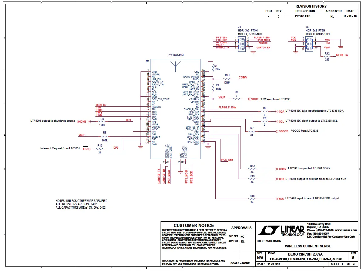
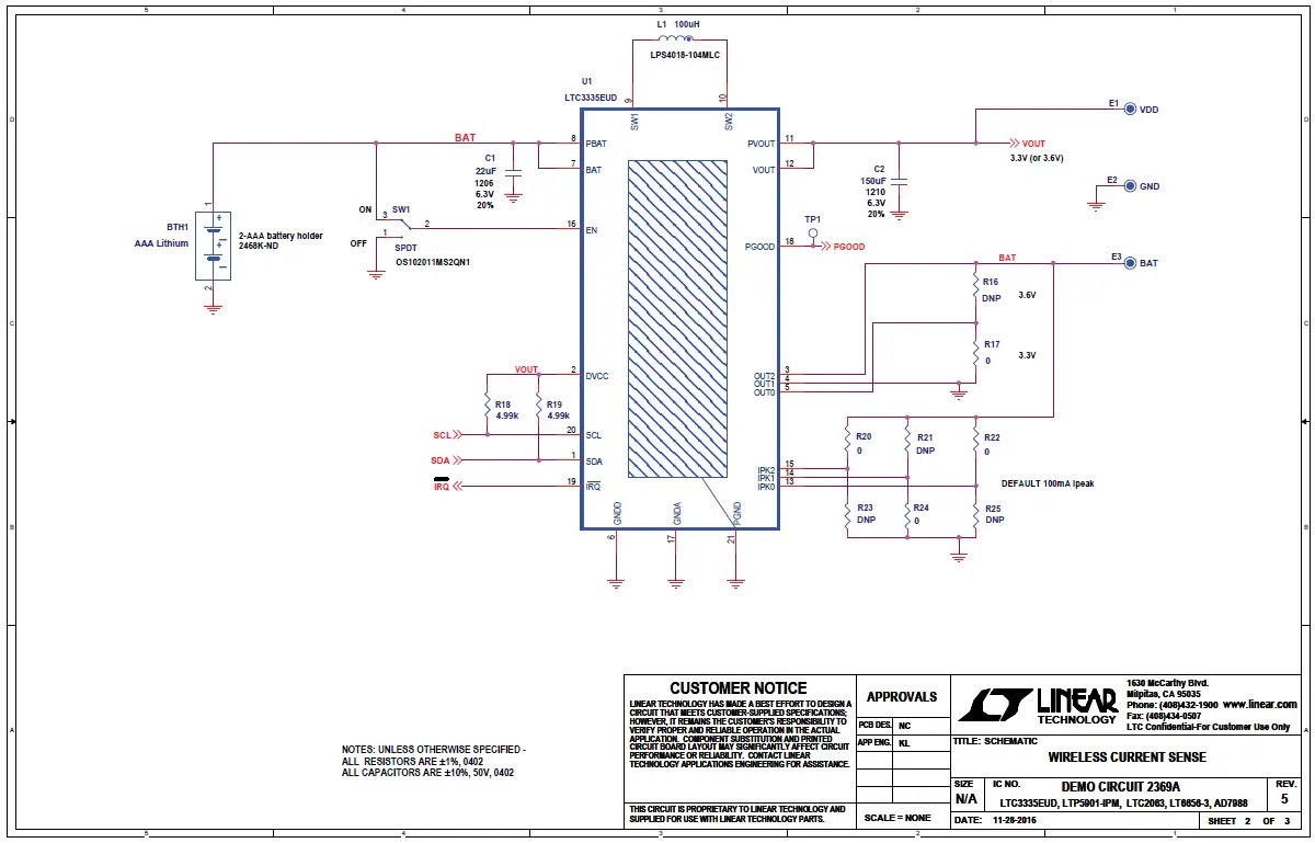
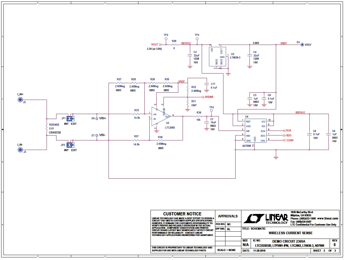
SCHEMATIC DIAGRAM


Information furnished by Linear Technology Corporation is believed to be accurate and reliable. However, no responsibility is assumed for its use. Linear Technology Corporation makes no representation that the interconnection of its circuits as described herein will not infringe on existing patent rights.
DEMONSTRATION BOARD IMPORTANT NOTICE
Linear Technology Corporation (LTC) provides the enclosed product(s) under the following AS IS conditions:
This demonstration board (DEMO BOARD) kit being sold or provided by Linear Technology is intended for use for ENGINEERING DEVELOPMENT OR EVALUATION PURPOSES ONLY and is not provided by LTC for commercial use. As such, the DEMO BOARD herein may not be complete in terms of required design-, marketing-, and/or manufacturing-related protective considerations, including but not limited to product safety measures typically found in finished commercial goods. As a prototype, this product does not fall within the scope of the European Union directive on electromagnetic compatibility and therefore may or may not meet the technical requirements of the directive, or other regulations. If this evaluation kit does not meet the specifications recited in the DEMO BOARD manual the kit may be returned within 30 days from the date of delivery for a full refund.
THE FOREGOING WARRANTY IS THE EXCLUSIVE WARRANTY MADE BY THE SELLER TO THE BUYER AND IS IN LIEU OF ALL OTHER WARRANTIES, EXPRESSED, IMPLIED, OR STATUTORY, INCLUDING ANY WARRANTY OF MERCHANTABILITY OR FITNESS FOR ANY PARTICULAR PURPOSE. EXCEPT TO THE EXTENT OF THIS INDEMNITY, NEITHER PARTY SHALL BE LIABLE TO THE OTHER FOR ANY INDIRECT, SPECIAL, INCIDENTAL, OR CONSEQUENTIAL DAMAGES.
The user assumes all responsibility and liability for the proper and safe handling of the goods. Further, the user releases LTC from all claims arising from the handling or use of the goods. Due to the open construction of the product, it is the user’s responsibility to take any and all appropriate precautions with regard to electrostatic discharge. Also be aware that the products herein may not be regulatory compliant or agency-certified (FCC, UL, CE, etc.). No License is granted under any patent right or other intellectual property whatsoever. LTC assumes no liability for applications assistance, customer product design, software performance, or infringement of patents or any other intellectual property rights of any kind. LTC currently services a variety of customers for products around the world, and therefore this transaction is not exclusive. Please read the DEMO BOARD manual prior to handling the product. Persons handling this product must have electronics training and observe good laboratory practice standards. Common sense is encouraged. This notice contains important safety information about temperatures and voltages. For further safety concerns, please contact an LTC application engineer.
Mailing Address:
Linear Technology
1630 McCarthy Blvd.
Milpitas,
CA 95035
Copyright © 2004,
Linear Technology Corporation
LT 0417
PRINTED IN USA
LINEAR TECHNOLOGY CORPORATION 2017
Downloaded from Arrow.com.


