![]() ALIO Style
ALIO Style
ALIO Vend
RADIO MODULE 4G
Integration
Manual
Revision R01
P/N: MAE5015
Mod.N: Q059R06
SCOPE
The purpose of the document is to describe how to assembly the Radio Module 4G into ALIO Style / ALIO
Vend devices.
FCC PRESCRIPTIONS
The optional LTE HL7618RD Radio module, in order to be compliant with FCC requirements, must respect the following:
- The LTE HL7618RD Radio module has been approved for use in the USA (United States of America)
- The LTE HL7618RD Radio module is not suitable for use in Canada
- At least a 20 cm separation distance between the antenna and the user’s body must be maintained at all times.
- The LTE HL7618RD Radio module must not transmit simultaneously with NFC Antenna or Bluetooth.
- When the LTE HL7618RD Radio module is installed inside the product, the provided label bearing the writing “This device contains FCC ID: N7NHL7618RD” must be applied to the product as stated in the Radio module assembly manual.
- To comply with FCC regulations limiting both maximum RF output power and human exposure to RF radiation, the maximum antenna gain including cable loss in a mobile-only exposure condition must not exceed:
o 5 dBi in LTE Band 4
o 9 dBi in LTE Band 13 - The installation of the LTE HL7618RD Radio module must be done by authorized personnel.
Changes or modifications made to the equipment not expressly approved by MADIC ITALIA S.P.A. may void the FCC authorization to operate this equipment.
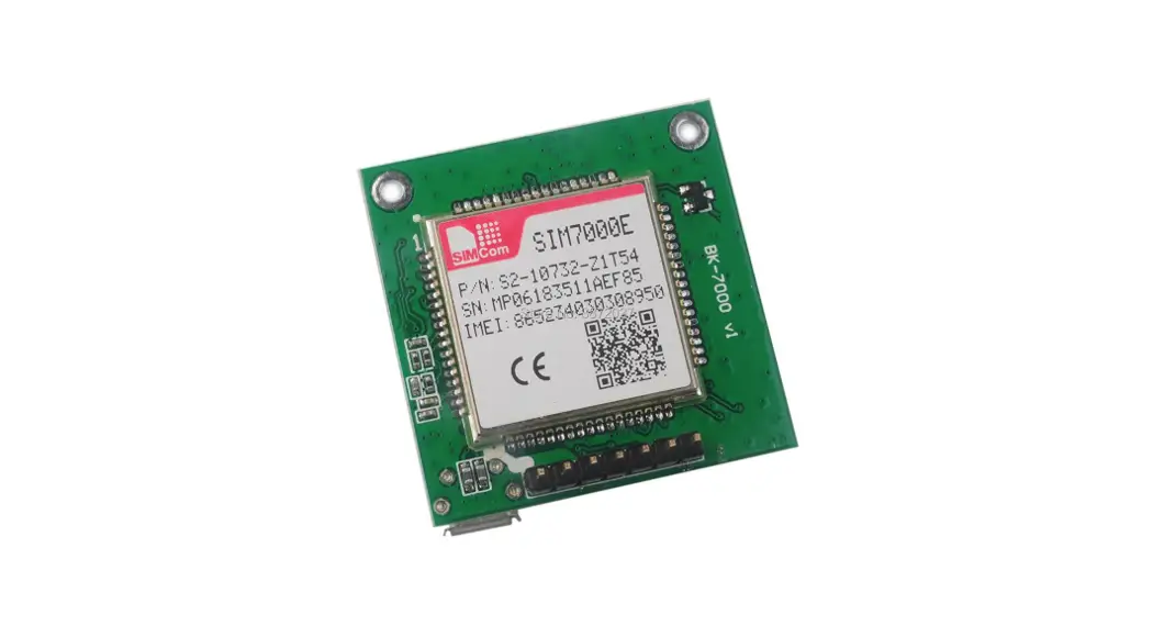
RADIO MODULE OVERVIEW
The Radio module mounts a Sierra Wireless HL7618RD (FCC ID: N7NHL7618RD) and interfaces itself with the terminal through a custom connector (only Radio Module designed by MADIC ITALIA can be interfaced with the terminal).
The Sierra Wireless HL7618RD has fixed carrier VERIZON and hence can be used only in the USA.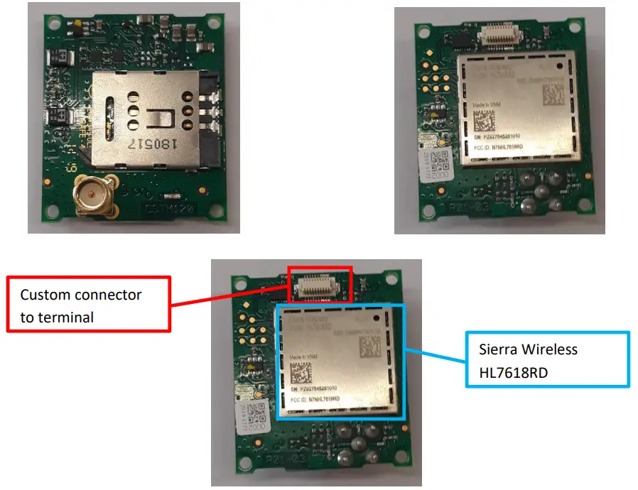
ASSEMBLY OF THE 4G RADIO MODULE INTO ALIO STYLE
This operation must be done by the authorized personnel that performs the terminal installation.
The terminal must be powered off and disconnected from the power supply during the execution of the activities.
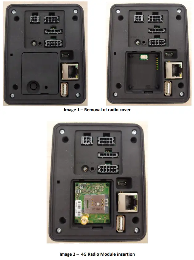
- Remove the plastic cover on the back of the terminal as shown in Image 1.
- Insert the 4G radio module into the cavity present in the back plastic cover of the terminal, taking care to align the holes in the 4 corners of the module with the 4 plastic turrets in the terminal cavity as shown in Image 2.

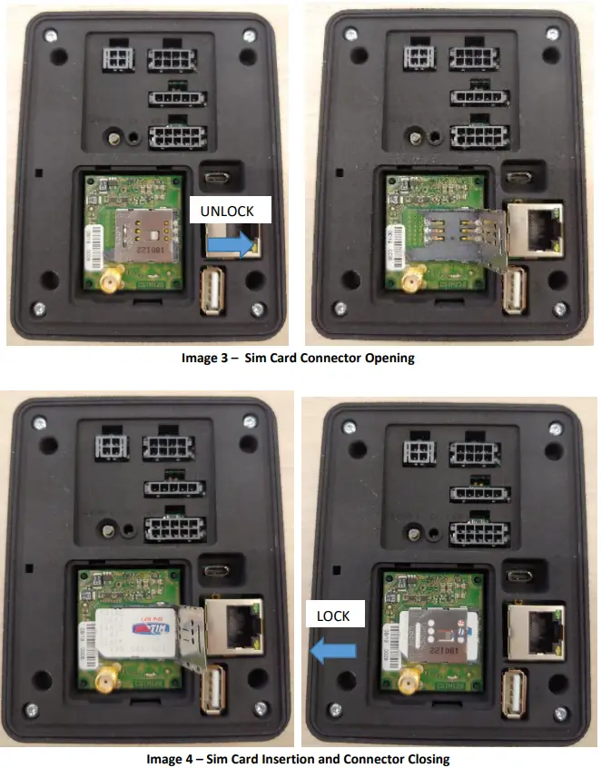
- Before insert the SIM, unlock the metal SIM cover sliding it toward the right. Lift up the connector and insert the SIM. (Image 3).
Close the metal SIM cover and lock it sliding it toward the left. (Image4)
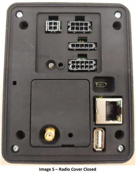
- Insert the Radio Cover on the terminal as shown in Image 5

ASSEMBLY OF THE 4G RADIO MODULE INTO ALIO VEND
The terminal must be powered off and disconnected from the power supply during the execution of the activities.
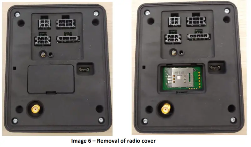
- Remove the SIM cover on the back of the terminal as shown in Image 6.

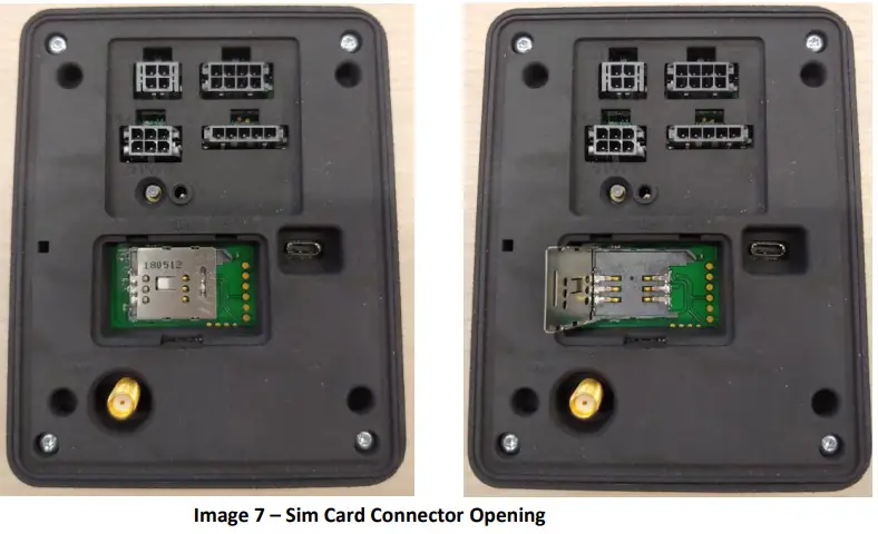
- Before inserting the SIM, unlock the metal SIM cover sliding it toward the right. Lift up the connector and insert the SIM. (Image 7).
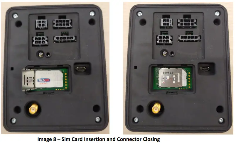
Close the metal SIM cover and lock it sliding it toward the left. (Image8)

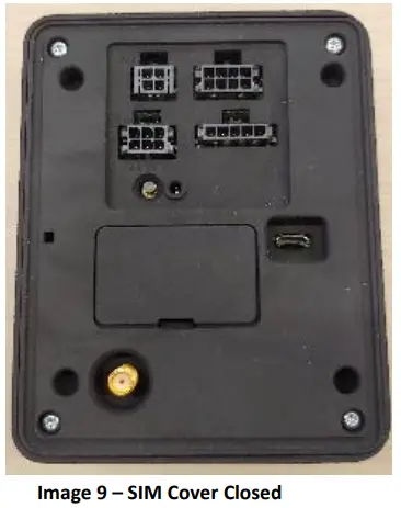
- Insert the SIM Cover on the terminal as shown in Image 9.

4G RADIO MODULE ANTENNA
The antenna of the 4G radio module must be connected to the SMA connector. The antenna must have a cable with a length of more than 1 meter. At least a 20 cm separation distance between the antenna and the user’s body must be maintained at all times.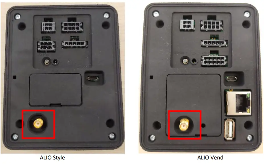
1.1 EXAMPLE OF ANTENNAS
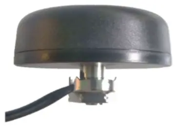
 4G BODY MOUNT ANTENNA Part Number 592C
Applications
– Automotive
– loT devices
Main features
– Low profile
– RoHS Compliant
– 1P67
– Compact structure
Main Specifications 4G CHANNEL
| Parameter/Frequency Band | 700-960 MHz | 1710-2170 MHz | 2500-2700 MHz |
| Gain (dBi) | 2.0 | 4.5 | 6.6 |
| VSWR | <2.9 | <2,0 | <2,0 |
| Imp. (Ohm) | 50 | 50 | 50 |
| Polarization | Linear | Linear | Mostly linear |
| Radiation Pattern | Omnidirectional | Omnidirectional | Omnidirectional |

SPECIFICATIONS
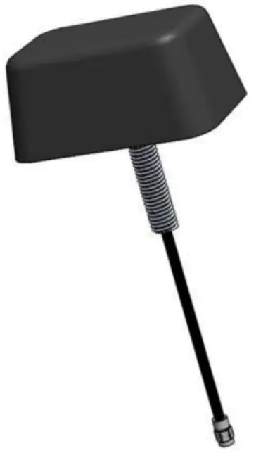
Part Number: 650-10010-01
Product Name: LTE 201A (Mini-GP Antenna)
Features: External Mounted
698 — 960 MHz/1710-2170 MHz/ 2300 — 2700 MHz/2900 — 3500MHzt
Single Antenna (SISO) 1.83m Low-loss cable
IP67 Waterproof (Upper mounting portion) 2″ Threaded Mount
RoHS Compliant
| PARAMETER | SPECIFICATION (with 1.83m Cable) |
| Frequency of Operation | 698 to 960 MHz, 1710 to 1990 MHz, 1920 to 2170 MHz, 2100 to 2500MHz, 2500 to 2700 MHz, 2900 to 3500 MHz |
| Return Loss (698-2.76Hz LTE) | c -6dB |
| Return Loss (2.9 -3.5GHz) | < -5dB |
| Efficiency (698 to 787 MHz) | >50% |
| Efficiency (824-896 MHz) | >25% |
| Efficiency (880-960 MHz) | >50% |
| Efficiency (1710 to 1990 MHz) | >60% |
| Efficiency (2100 to 2500 MHz) | >50% |
| Efficiency (2500 to 2700 MHz) | >40% |
| Efficiency (2900 to 3500 MHz) | >20% |
¹- denotes reduced performance over the band
REVISION INDEX
| Revision | Author | Change descriptions |
| R01 | R.B. | First Issue |
HOW TO CONTACT US
Dear customer thanks you for the choice of our products.
To satisfy any of your requirements you can contact us at the following address:
![]()
MAGIC ITALIA S.p.A.
Via Volta 39 – 21010 Cardano al Campo (Varese)
Italy
Tel. +39 0331 904454
Fax +39 0331 901835
Internet: www.globalcom-eng.com
e-mail: [email protected]
MAGIC ITALIA pursues a policy of continued effort to improve the quality of its products and evidence published. To this are constantly dedicated resources to ensure the accuracy of the information contained in the documents.
We will be grateful if you find missing information or not accurate if you report to us using the electronic mailbox: [email protected].
MAGIC ITALIA reserves the right to make changes to the information contained in this document to improve the description or anything.
MAGIC ITALIA assumes no liability arising from the use of this information or errors and omissions in such information.


